


SECTION 3 - CHASSIS & TURNTABLE
3-184
3121160
6.
If the oil level is below the "ADD" mark, proceed to Step
7 and 8 and reinstall the dipstick into the dipstick tube.
7.
Remove the oil filter cap from the valve rocker arm
cover.
8.
Add the required amount of oil to bring the level up to
but not over "FULL" mark on the dipstick.
9.
Reinstall the oil fill cap to the valve rocker cover and
wipe away any excess oil.
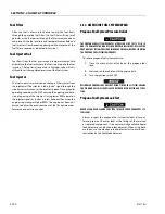
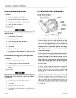
Changing The Engine Oil
WHEN CHANGING THE OIL, ALWAYS CHANGE THE OIL FILTER. CHANGE OIL
WHEN THE ENGINE IS WARM FROM OPERATION AS THE OILS WILL FLOW
FREELY AND CARRY AWAY MORE IMPURITIES.
To change the oil use the following steps:
1.
Start the engine and run until it reaches normal operat-
ing temperature.
2.
Stop the engine.
3.
Remove the drain plug and allow the oil to drain.
4.
Remove and discard the oil filter and its sealing ring.
5.
Coat the sealing ring on the filter with clean engine oil
and wipe the sealing surface on the filter mounting
surface to remove any dust, dirt and debris. Tighten the
filter securely (follow the filter manufacturers instruc-
tions). Do not over tighten.
6.
Check the sealing ring on drain plug for any damage,
replace if necessary, wipe the plug with a clean rag,
and wipe the sealing surface on the pan and reinstall the
pan plug. Do not over tighten.
7.
Fill the crankcase with oil.
8.
Start the engine and check for oil leaks.
9.
Stop the engine and check the oil level to insure the oil
level is at "FULL".
10.
Dispose of the oil and filter in a safe manner.
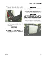
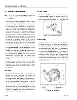
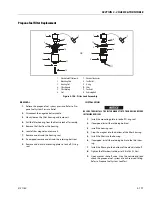
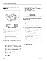
Coolant Fill Procedure - Dual Fuel Engine
DAMAGE TO THE ENGINE COULD OCCUR IF NOT PROPERLY FILLED WITH COOL-
ANT. LPG FUELED ENGINES ARE MOST PRONE TO CREATING AN AIR LOCK DUR-
ING A COOLANT FILL OPERATION DUE TO THE ELECTRONIC PRESSURE
REGULATOR (EPR) BEING THE HIGHEST POINT IN THE COOLING SYSTEM. AN
EPR THAT APPEARS TO HAVE FROST FORMING ON IT IS A SIGN THAT THE
ENGINE COOLING SYSTEM CONTAINS AIR. THE APPEARANCE AND TEMPERA-
TURE OF THE EPR SHOULD BE MONITORED DURING THE COOLANT FILL OPER-
ATION. A WARM EPR IS AN INDICATION THAT THE COOLING SYSTEM IS
PROPERLY FILLED AND FUNCTIONING.
MAKE SURE ENGINE IS COOL BEFORE PERFORMING ANY MAINTENANCE
WORK.
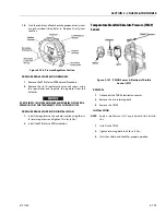
1.
Loosen the worm gear clamp on the coolant line run-
ning into the EPR as shown below and remove the hose
from the EPR. Place a rag under the hose to prevent
coolant from running onto the engine/machine.
Содержание 740AJ
Страница 1: ...Service and Maintenance Manual Model 740AJ Prior to S N 0300185827 P N 3121160 October 24 2017 AS NZS...
Страница 2: ......
Страница 51: ...SECTION 2 GENERAL 3121160 2 11 Figure 2 2 Engine Operating Temperature Specifications Ford 4150548 E...
Страница 55: ...SECTION 3 CHASSIS TURNTABLE 3121160 3 3 This page left blank intentionally...
Страница 56: ...SECTION 3 CHASSIS TURNTABLE 3 4 3121160 1 Figure 3 2 Axle and Steering Installation Sheet 1 of 2 0258286 C...
Страница 100: ...SECTION 3 CHASSIS TURNTABLE 3 48 3121160 Figure 3 37 Swing Bearing Tolerance Boom Placement Sheet 1 of 2...
Страница 101: ...SECTION 3 CHASSIS TURNTABLE 3121160 3 49 Figure 3 38 Swing Bearing Tolerance Boom Placement Sheet 2 of 2...
Страница 116: ...SECTION 3 CHASSIS TURNTABLE 3 64 3121160 Figure 3 44 Swing Hub Prior to SN 0300074383...
Страница 124: ...SECTION 3 CHASSIS TURNTABLE 3 72 3121160 Figure 3 45 Swing Drive Hub Fairfield SN 0300074383 through 0300134352...
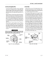
Страница 180: ...SECTION 3 CHASSIS TURNTABLE 3 128 3121160 1 Figure 3 66 Auxiliary Pump Location 1 AuxiliaryPump 2 HydraulicTank...
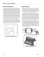
Страница 203: ...SECTION 3 CHASSIS TURNTABLE 3121160 3 151 Figure 3 77 EFI Component Location...
Страница 206: ...SECTION 3 CHASSIS TURNTABLE 3 154 3121160 Figure 3 78 ECM EPM Identification ECM EPM...
Страница 213: ...SECTION 3 CHASSIS TURNTABLE 3121160 3 161 Megajector Regulator LockoffSolenoid Figure 3 80 LPG System Components Mixer...
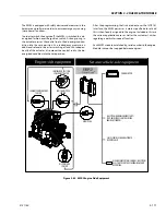
Страница 219: ...SECTION 3 CHASSIS TURNTABLE 3121160 3 167 Figure 3 81 Check Out and Initial Start Up Procedures...
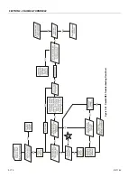
Страница 224: ...SECTION 3 CHASSIS TURNTABLE 3 172 3121160 Figure 3 83 Deutz EMR 2 Troubleshooting Flow Chart...
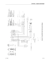
Страница 225: ...SECTION 3 CHASSIS TURNTABLE 3121160 3 173 Figure 3 84 Deutz EMR 2 Vehicle Side Connection Diagram...
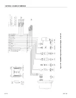
Страница 226: ...SECTION 3 CHASSIS TURNTABLE 3 174 3121160 Figure 3 85 Deutz EMR 2 Engine Side Connection Diagram Sheet 1 of 2...
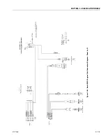
Страница 227: ...SECTION 3 CHASSIS TURNTABLE 3121160 3 175 Figure 3 86 Deutz EMR 2 Engine Side Connection Diagram Sheet 2 of 2...
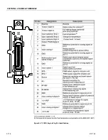
Страница 228: ...SECTION 3 CHASSIS TURNTABLE 3 176 3121160 Figure 3 87 EMR 2 Engine Plug Pin Identification...
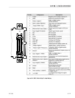
Страница 229: ...SECTION 3 CHASSIS TURNTABLE 3121160 3 177 Figure 3 88 EMR 2 Vehicle Plug Pin Identification...
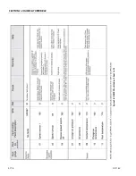
Страница 230: ...SECTION 3 CHASSIS TURNTABLE 3 178 3121160 Figure 3 89 EMR2 Fault Codes Sheet 1 of 5...
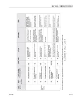
Страница 231: ...SECTION 3 CHASSIS TURNTABLE 3121160 3 179 Figure 3 90 EMR2 Fault Codes Sheet 2 of 5...
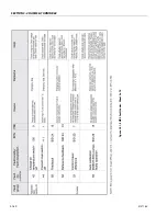
Страница 232: ...SECTION 3 CHASSIS TURNTABLE 3 180 3121160 Figure 3 91 EMR2 Fault Codes Sheet 3 of 5...
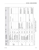
Страница 233: ...SECTION 3 CHASSIS TURNTABLE 3121160 3 181 Figure 3 92 EMR2 Fault Codes Sheet 4 of 5...
Страница 234: ...SECTION 3 CHASSIS TURNTABLE 3 182 3121160 Figure 3 93 EMR2 Fault Codes Sheet 5 of 5...
Страница 303: ...SECTION 4 BOOM PLATFORM 3121160 4 31 Figure 4 20 Rotator Assembly HELAC...
Страница 335: ...SECTION 4 BOOM PLATFORM 3121160 4 63 THIS SENSOR ON NON ADE MACHINES ONLY Figure 4 27 UMS Sensor Location...
Страница 336: ...SECTION 4 BOOM PLATFORM 4 64 3121160 Figure 4 28 UMS Module Location ADE MACHINES NON ADE MACHINES...
Страница 425: ...SECTION 5 BASIC HYDRAULIC INFORMATION AND SCHEMATICS 3121160 5 81 Figure 5 131 Variable Displacement Pump Rexroth...
Страница 443: ...SECTION 5 BASIC HYDRAULIC INFORMATION AND SCHEMATICS 3121160 5 99 Figure 5 146 Fault Logic Troubleshooting...
Страница 444: ...SECTION 5 BASIC HYDRAULIC INFORMATION AND SCHEMATICS 5 100 3121160 Figure 5 147 Fault Logic Troubleshooting...
Страница 445: ...SECTION 5 BASIC HYDRAULIC INFORMATION AND SCHEMATICS 3121160 5 101 Figure 5 148 Fault Logic Troubleshooting...
Страница 460: ...SECTION 5 BASIC HYDRAULIC INFORMATION AND SCHEMATICS 5 116 3121160 NOTES...
Страница 467: ...SECTION 6 JLG CONTROL SYSTEM 3121160 6 7 Figure 6 2 ADE Block Diagram...
Страница 471: ...SECTION 6 JLG CONTROL SYSTEM 3121160 6 11 Figure 6 6 Analyzer Flow Chart Prior to Version 5 X Software Sheet 4 of 4...
Страница 473: ...SECTION 6 JLG CONTROL SYSTEM 3121160 6 13 Figure 6 8 Analyzer Flow Chart Version 5 X Software Sheet 2 of 4...
Страница 534: ...SECTION 6 JLG CONTROL SYSTEM 6 74 3121160 NOTES...
Страница 545: ...SECTION 7 BASIC ELECTRICAL INFORMATION SCHEMATICS 3121160 7 11 Figure 7 15 Connector Installation...
Страница 580: ...SECTION 7 BASIC ELECTRICAL INFORMATION SCHEMATICS 7 46 3121160 NOTES...
Страница 581: ......


