SECTION 3 - CHASSIS & TURNTABLE
3121160
3-165
Wiring
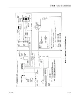
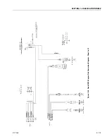
See wiring diagram for details of hook-up.
Use #16 wire minimum.
Keep all wiring to the Governor as short as is practical.
Go directly from the controller ground terminal (B of the 8 pin
connector) by dedicated wire, to the battery “minus” terminal.
If this cannot be done, for some reason, go by dedicated wire
to a very good engine ground.
A properly functioning engine electrical system will supply
13.5 - 14.8 VDC when the engine is running. If wiring size is
adequate, with good connections and proper grounds, you
will get this reading between the wires terminals A & B of the 8
pin connector when the Governor is controlling engine speed.
Verify this. Improper hook-up can damage electronics. Re-
check wiring before applying power.
Power Distribution
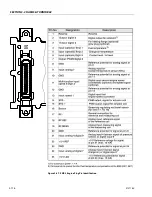
8 PIN CONNECTOR
Pin:
a.
12 VDC from the make before break oil pressure
switch. This switch provides power to pin A when
the ignition is on and the engine is not running (no
oil pressure), or when the ignition is turned off when
the engine is running (has oil pressure).
b.
Ground.
c.
Tach signal from the engine ignition system.
d.
Tach signal from the engine ignition system.
e.
Control signal to operate the Actuator.
f.
Control signal to operate the Actuator.
g.
Removes ground from the start lock out relay when
the engine is running above the start lock out set
point. A 20 turn pot is provided to adjust this set
point. (usually around 500 RPM)
h.
Removes ground from the overspeed relay if this
point is exceeded. A 20 turn pot is provided to
adjust this set point.(usually around 5000 RPM)
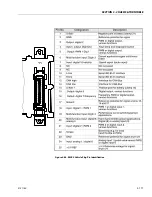
4 PIN CONNECTOR
Pin:
a.
Input from the elevation limit switches to allow high
engine to operate.
b.
Input from the high engine switch.
c.
Input for mid engine from one of the following: The
engine low coolant temperature switch, platform
footswitch, or a ground control directional switch.
d.
Provides ground to lockout start when the engine
RPMS exceed the set point.
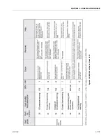
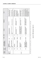
Check-Out and Initial Start-Up Procedures
Before proceeding, familiarize yourself with the locations of
the various adjustment pots.
Adjustments:
High engine
Mid engine
Start lockout
Over speed lockout
Factory adjust
Gain
HIGH ENGINE:
This adjustment is made by turning the 1/8 in. brass screw
clockwise (CW ) to increase speed, and counterclockwise
(CCW) to decrease speed. The adjustment range of the high
engine pot is 25 turns, each turn will change engine speed by
about 100 to 200 RPMS. This pot is protected by a slip clutch at
each end and will not be harmed by moderate over-adjust-
ment. However the governor will not function when the pot is
past full travel. If you suspect that you may have over-adjusted
the high engine pot, or have lost track of where you are, turn
the pot 25 to 30 turns out (CCW), then turn in (CW) 10 turns.
This will get you back into the range you should be in. Make
the high engine adjustment first, then gain, then reset high
engine.
GAIN:
This adjustment is made by turning the plastic screw clock-
wise (CW to increase governor sensitivity, counterclockwise
(CCW) to decrease sensitivity. The adjustment range of the
Factory pot is about 3/4 of a turn, AND OVERTURNING WILL
BREAK THE INTERNAL STOPS, making further adjustments
impossible. Too much gain will cause instability and the
engine will pulsate, Not enough gain will make the engine
slow to respond to load requirements, and at first appears to
be a good setting when operating directional functions other
than drive. The engine will accelerate right up to the set RPMS
and stop at that point.The problem with this type of gain set-
ting is that when a large load is applied (usually through drive)
and then suddenly unloaded, the engine will be slow to
respond in decreasing RPMS. This will cause the engine to over
rev and then at times, will activate the over speed cutout and
shut the engine off. The ideal gain setting will provide a com-
promise between quick response and good stability. This will
usually show up as 1 to 3 engine pulsation’s before leveling
out at the set RPMS when going from idle to high engine.
Содержание 740AJ
Страница 1: ...Service and Maintenance Manual Model 740AJ Prior to S N 0300185827 P N 3121160 October 24 2017 AS NZS...
Страница 2: ......
Страница 51: ...SECTION 2 GENERAL 3121160 2 11 Figure 2 2 Engine Operating Temperature Specifications Ford 4150548 E...
Страница 55: ...SECTION 3 CHASSIS TURNTABLE 3121160 3 3 This page left blank intentionally...
Страница 56: ...SECTION 3 CHASSIS TURNTABLE 3 4 3121160 1 Figure 3 2 Axle and Steering Installation Sheet 1 of 2 0258286 C...
Страница 100: ...SECTION 3 CHASSIS TURNTABLE 3 48 3121160 Figure 3 37 Swing Bearing Tolerance Boom Placement Sheet 1 of 2...
Страница 101: ...SECTION 3 CHASSIS TURNTABLE 3121160 3 49 Figure 3 38 Swing Bearing Tolerance Boom Placement Sheet 2 of 2...
Страница 116: ...SECTION 3 CHASSIS TURNTABLE 3 64 3121160 Figure 3 44 Swing Hub Prior to SN 0300074383...
Страница 124: ...SECTION 3 CHASSIS TURNTABLE 3 72 3121160 Figure 3 45 Swing Drive Hub Fairfield SN 0300074383 through 0300134352...
Страница 180: ...SECTION 3 CHASSIS TURNTABLE 3 128 3121160 1 Figure 3 66 Auxiliary Pump Location 1 AuxiliaryPump 2 HydraulicTank...
Страница 203: ...SECTION 3 CHASSIS TURNTABLE 3121160 3 151 Figure 3 77 EFI Component Location...
Страница 206: ...SECTION 3 CHASSIS TURNTABLE 3 154 3121160 Figure 3 78 ECM EPM Identification ECM EPM...
Страница 213: ...SECTION 3 CHASSIS TURNTABLE 3121160 3 161 Megajector Regulator LockoffSolenoid Figure 3 80 LPG System Components Mixer...
Страница 219: ...SECTION 3 CHASSIS TURNTABLE 3121160 3 167 Figure 3 81 Check Out and Initial Start Up Procedures...
Страница 224: ...SECTION 3 CHASSIS TURNTABLE 3 172 3121160 Figure 3 83 Deutz EMR 2 Troubleshooting Flow Chart...
Страница 225: ...SECTION 3 CHASSIS TURNTABLE 3121160 3 173 Figure 3 84 Deutz EMR 2 Vehicle Side Connection Diagram...
Страница 226: ...SECTION 3 CHASSIS TURNTABLE 3 174 3121160 Figure 3 85 Deutz EMR 2 Engine Side Connection Diagram Sheet 1 of 2...
Страница 227: ...SECTION 3 CHASSIS TURNTABLE 3121160 3 175 Figure 3 86 Deutz EMR 2 Engine Side Connection Diagram Sheet 2 of 2...
Страница 228: ...SECTION 3 CHASSIS TURNTABLE 3 176 3121160 Figure 3 87 EMR 2 Engine Plug Pin Identification...
Страница 229: ...SECTION 3 CHASSIS TURNTABLE 3121160 3 177 Figure 3 88 EMR 2 Vehicle Plug Pin Identification...
Страница 230: ...SECTION 3 CHASSIS TURNTABLE 3 178 3121160 Figure 3 89 EMR2 Fault Codes Sheet 1 of 5...
Страница 231: ...SECTION 3 CHASSIS TURNTABLE 3121160 3 179 Figure 3 90 EMR2 Fault Codes Sheet 2 of 5...
Страница 232: ...SECTION 3 CHASSIS TURNTABLE 3 180 3121160 Figure 3 91 EMR2 Fault Codes Sheet 3 of 5...
Страница 233: ...SECTION 3 CHASSIS TURNTABLE 3121160 3 181 Figure 3 92 EMR2 Fault Codes Sheet 4 of 5...
Страница 234: ...SECTION 3 CHASSIS TURNTABLE 3 182 3121160 Figure 3 93 EMR2 Fault Codes Sheet 5 of 5...
Страница 303: ...SECTION 4 BOOM PLATFORM 3121160 4 31 Figure 4 20 Rotator Assembly HELAC...
Страница 335: ...SECTION 4 BOOM PLATFORM 3121160 4 63 THIS SENSOR ON NON ADE MACHINES ONLY Figure 4 27 UMS Sensor Location...
Страница 336: ...SECTION 4 BOOM PLATFORM 4 64 3121160 Figure 4 28 UMS Module Location ADE MACHINES NON ADE MACHINES...
Страница 425: ...SECTION 5 BASIC HYDRAULIC INFORMATION AND SCHEMATICS 3121160 5 81 Figure 5 131 Variable Displacement Pump Rexroth...
Страница 443: ...SECTION 5 BASIC HYDRAULIC INFORMATION AND SCHEMATICS 3121160 5 99 Figure 5 146 Fault Logic Troubleshooting...
Страница 444: ...SECTION 5 BASIC HYDRAULIC INFORMATION AND SCHEMATICS 5 100 3121160 Figure 5 147 Fault Logic Troubleshooting...
Страница 445: ...SECTION 5 BASIC HYDRAULIC INFORMATION AND SCHEMATICS 3121160 5 101 Figure 5 148 Fault Logic Troubleshooting...
Страница 460: ...SECTION 5 BASIC HYDRAULIC INFORMATION AND SCHEMATICS 5 116 3121160 NOTES...
Страница 467: ...SECTION 6 JLG CONTROL SYSTEM 3121160 6 7 Figure 6 2 ADE Block Diagram...
Страница 471: ...SECTION 6 JLG CONTROL SYSTEM 3121160 6 11 Figure 6 6 Analyzer Flow Chart Prior to Version 5 X Software Sheet 4 of 4...
Страница 473: ...SECTION 6 JLG CONTROL SYSTEM 3121160 6 13 Figure 6 8 Analyzer Flow Chart Version 5 X Software Sheet 2 of 4...
Страница 534: ...SECTION 6 JLG CONTROL SYSTEM 6 74 3121160 NOTES...
Страница 545: ...SECTION 7 BASIC ELECTRICAL INFORMATION SCHEMATICS 3121160 7 11 Figure 7 15 Connector Installation...
Страница 580: ...SECTION 7 BASIC ELECTRICAL INFORMATION SCHEMATICS 7 46 3121160 NOTES...
Страница 581: ......

