SECTION 3 - CHASSIS & TURNTABLE
3-164
3121160
Linkage
1/4 in. -28 threaded rod and low friction rod-end bearings are
recommended for linkage materials.
Keep the linkage as short and as straight as possible.
The linkage must not rub against the engine, brackets, hoses,
etc. The linkage must be free of friction and lost motion or
“slop”.
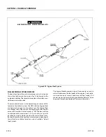
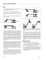
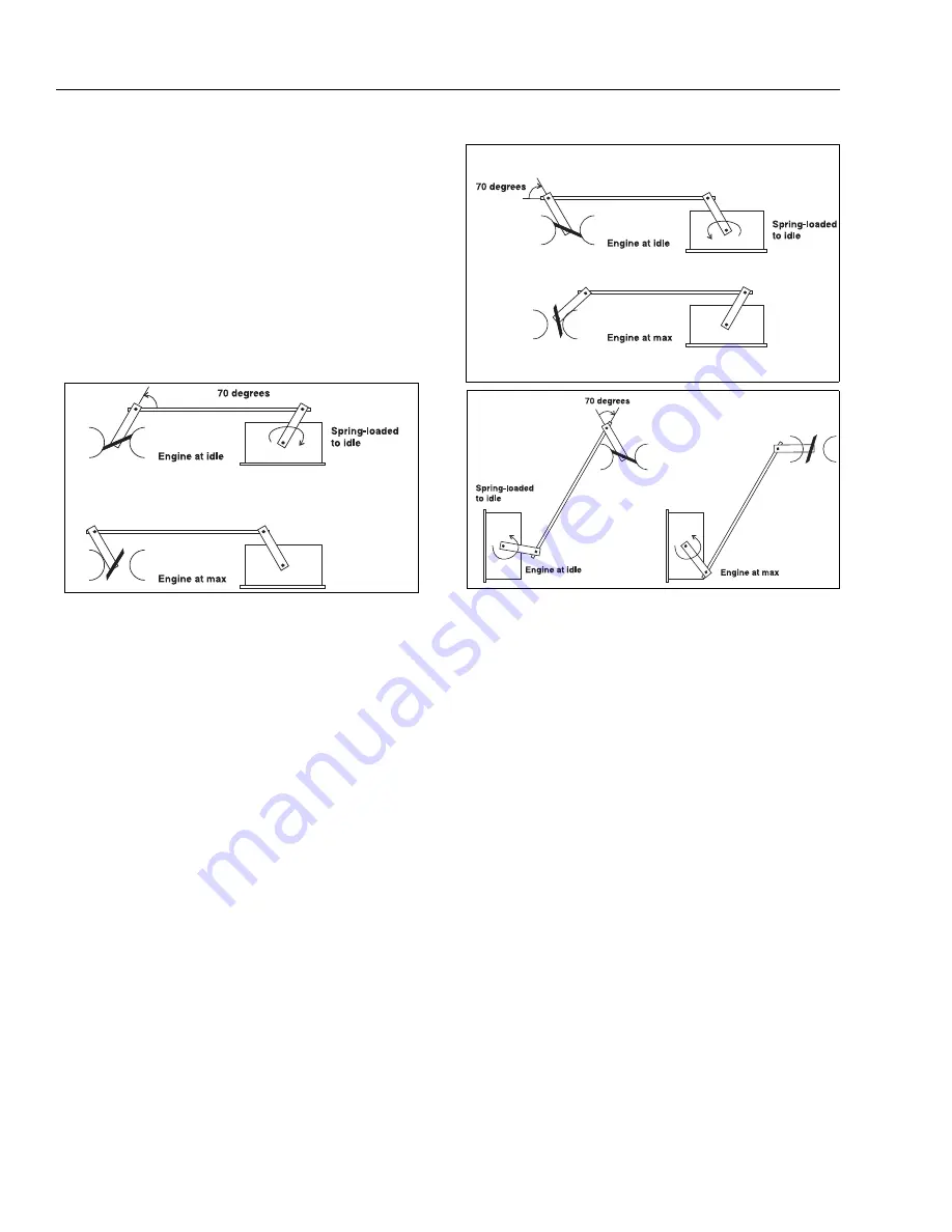
The following sketch indicates the proper linkage geometry
for most installations.
Note that the angle between the carburetor arm and the rod is
70 degrees with the engine at idle. This is highly desirable!
Note also that the Actuator arm travels equally on either side
of a 90 degree angle with the rod. This angular arrangement
will give the proper mechanical gain for good stability and
performance. It may be necessary to rotate the carburetor arm
relative to the butterfly to achieve this. This can usually be
done, and is usually worth the effort. Below are some work-
able installations, with good linkages. Remember, the Actuator
can be turned 180 degrees on its mounting to “reverse” the
spring-loaded direction. Also, the Actuator can be mounted in
any attitude.
The needed travel of the carburetor determines how far out on
the Actuator arm the rod is to be attached. In most cases, the
carburetor should be moved from closed to above 10 degrees
from full open as the Actuator is moved min. to max. THEN
ALTER THE LENGTH OF THE ROD SLIGHTLY (PERHAPS.030”), SO
THAT THE ACTUATOR IS JUST OFF ITS INTERNAL STOP, AND IS
PULLING THE BUTTERFLY AGAINST ITS STOP. This insures that
the carburetor can fully close to idle on load dumps, minimiz-
ing overspeeds.
Examine the system for springs, such as carburetor return
springs. These should be removed. Some automotive carbure-
tors (as opposed to industrial carburetors) contain internal
springs for accelerator pumps, etc. These may make good gov-
erning difficult, or even impossible. For this, and other reasons,
industrial carburetors are much to be preferred.
Move the linkage slowly through its travel, and look for any
binding or unexplained forces. Correct any before going fur-
ther.
Many “governing” problems are really caused by binding of
the butterfly and its shaft in the carburetor. This is caused by
loading due to vacuum under the butterfly and atmospheric
pressure above when the engine is running. These forces can-
not be felt when the engine is not running. Therefore, start the
engine while carefully controlling the speed by hand, and feel
for binding or airload forces. Needle bearings on the butterfly
shaft are available on many industrial carburetors to deal with
this problem. Any tendency on the butterfly stick must be cor-
rected.
Mounting-Controller
Select a reasonably cool, dry, and vibration free location.
The rear cover will probably need to be removed during set-up
in order to make adjustments for speed setting and gain. You
may wish to defer final installation until this is done.
After completing these adjustments, replace cover. Mount so
that water cannot pool on this cover. Always mount the con-
troller with the strain relief down. This will prevent water from
entering thru the cable, also place the vent hole in the bottom
of the controller down.
Содержание 740AJ
Страница 1: ...Service and Maintenance Manual Model 740AJ Prior to S N 0300185827 P N 3121160 October 24 2017 AS NZS...
Страница 2: ......
Страница 51: ...SECTION 2 GENERAL 3121160 2 11 Figure 2 2 Engine Operating Temperature Specifications Ford 4150548 E...
Страница 55: ...SECTION 3 CHASSIS TURNTABLE 3121160 3 3 This page left blank intentionally...
Страница 56: ...SECTION 3 CHASSIS TURNTABLE 3 4 3121160 1 Figure 3 2 Axle and Steering Installation Sheet 1 of 2 0258286 C...
Страница 100: ...SECTION 3 CHASSIS TURNTABLE 3 48 3121160 Figure 3 37 Swing Bearing Tolerance Boom Placement Sheet 1 of 2...
Страница 101: ...SECTION 3 CHASSIS TURNTABLE 3121160 3 49 Figure 3 38 Swing Bearing Tolerance Boom Placement Sheet 2 of 2...
Страница 116: ...SECTION 3 CHASSIS TURNTABLE 3 64 3121160 Figure 3 44 Swing Hub Prior to SN 0300074383...
Страница 124: ...SECTION 3 CHASSIS TURNTABLE 3 72 3121160 Figure 3 45 Swing Drive Hub Fairfield SN 0300074383 through 0300134352...
Страница 180: ...SECTION 3 CHASSIS TURNTABLE 3 128 3121160 1 Figure 3 66 Auxiliary Pump Location 1 AuxiliaryPump 2 HydraulicTank...
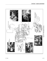
Страница 203: ...SECTION 3 CHASSIS TURNTABLE 3121160 3 151 Figure 3 77 EFI Component Location...
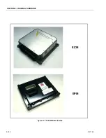
Страница 206: ...SECTION 3 CHASSIS TURNTABLE 3 154 3121160 Figure 3 78 ECM EPM Identification ECM EPM...
Страница 213: ...SECTION 3 CHASSIS TURNTABLE 3121160 3 161 Megajector Regulator LockoffSolenoid Figure 3 80 LPG System Components Mixer...
Страница 219: ...SECTION 3 CHASSIS TURNTABLE 3121160 3 167 Figure 3 81 Check Out and Initial Start Up Procedures...
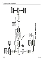
Страница 224: ...SECTION 3 CHASSIS TURNTABLE 3 172 3121160 Figure 3 83 Deutz EMR 2 Troubleshooting Flow Chart...
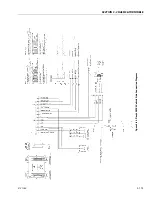
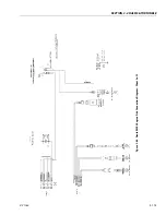
Страница 225: ...SECTION 3 CHASSIS TURNTABLE 3121160 3 173 Figure 3 84 Deutz EMR 2 Vehicle Side Connection Diagram...
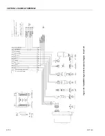
Страница 226: ...SECTION 3 CHASSIS TURNTABLE 3 174 3121160 Figure 3 85 Deutz EMR 2 Engine Side Connection Diagram Sheet 1 of 2...
Страница 227: ...SECTION 3 CHASSIS TURNTABLE 3121160 3 175 Figure 3 86 Deutz EMR 2 Engine Side Connection Diagram Sheet 2 of 2...
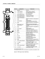
Страница 228: ...SECTION 3 CHASSIS TURNTABLE 3 176 3121160 Figure 3 87 EMR 2 Engine Plug Pin Identification...
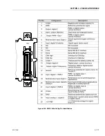
Страница 229: ...SECTION 3 CHASSIS TURNTABLE 3121160 3 177 Figure 3 88 EMR 2 Vehicle Plug Pin Identification...
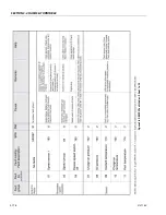
Страница 230: ...SECTION 3 CHASSIS TURNTABLE 3 178 3121160 Figure 3 89 EMR2 Fault Codes Sheet 1 of 5...
Страница 231: ...SECTION 3 CHASSIS TURNTABLE 3121160 3 179 Figure 3 90 EMR2 Fault Codes Sheet 2 of 5...
Страница 232: ...SECTION 3 CHASSIS TURNTABLE 3 180 3121160 Figure 3 91 EMR2 Fault Codes Sheet 3 of 5...
Страница 233: ...SECTION 3 CHASSIS TURNTABLE 3121160 3 181 Figure 3 92 EMR2 Fault Codes Sheet 4 of 5...
Страница 234: ...SECTION 3 CHASSIS TURNTABLE 3 182 3121160 Figure 3 93 EMR2 Fault Codes Sheet 5 of 5...
Страница 303: ...SECTION 4 BOOM PLATFORM 3121160 4 31 Figure 4 20 Rotator Assembly HELAC...
Страница 335: ...SECTION 4 BOOM PLATFORM 3121160 4 63 THIS SENSOR ON NON ADE MACHINES ONLY Figure 4 27 UMS Sensor Location...
Страница 336: ...SECTION 4 BOOM PLATFORM 4 64 3121160 Figure 4 28 UMS Module Location ADE MACHINES NON ADE MACHINES...
Страница 425: ...SECTION 5 BASIC HYDRAULIC INFORMATION AND SCHEMATICS 3121160 5 81 Figure 5 131 Variable Displacement Pump Rexroth...
Страница 443: ...SECTION 5 BASIC HYDRAULIC INFORMATION AND SCHEMATICS 3121160 5 99 Figure 5 146 Fault Logic Troubleshooting...
Страница 444: ...SECTION 5 BASIC HYDRAULIC INFORMATION AND SCHEMATICS 5 100 3121160 Figure 5 147 Fault Logic Troubleshooting...
Страница 445: ...SECTION 5 BASIC HYDRAULIC INFORMATION AND SCHEMATICS 3121160 5 101 Figure 5 148 Fault Logic Troubleshooting...
Страница 460: ...SECTION 5 BASIC HYDRAULIC INFORMATION AND SCHEMATICS 5 116 3121160 NOTES...
Страница 467: ...SECTION 6 JLG CONTROL SYSTEM 3121160 6 7 Figure 6 2 ADE Block Diagram...
Страница 471: ...SECTION 6 JLG CONTROL SYSTEM 3121160 6 11 Figure 6 6 Analyzer Flow Chart Prior to Version 5 X Software Sheet 4 of 4...
Страница 473: ...SECTION 6 JLG CONTROL SYSTEM 3121160 6 13 Figure 6 8 Analyzer Flow Chart Version 5 X Software Sheet 2 of 4...
Страница 534: ...SECTION 6 JLG CONTROL SYSTEM 6 74 3121160 NOTES...
Страница 545: ...SECTION 7 BASIC ELECTRICAL INFORMATION SCHEMATICS 3121160 7 11 Figure 7 15 Connector Installation...
Страница 580: ...SECTION 7 BASIC ELECTRICAL INFORMATION SCHEMATICS 7 46 3121160 NOTES...
Страница 581: ......


