SECTION 5 - BASIC HYDRAULICS INFORMATION & SCHEMATICS
5-24
31215031
NOTE:
Piston and mating end of rod must be free of oil when
installing tapered bushing.
9.
Thread piston on rod until it aligns with spacer.
NOTE:
Apply Medium Strength Threadlocking Compound to new
JLG furnished tapered bushing capscrews when rebuilding
master, slave, lift, and telescope cylinders.
10.
Insert tapered bushing loosely in the piston. Install JLG
capscrews (not vendor capscrews) through drilled holes
in the bushing and tapped holes in piston.
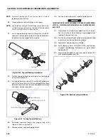
Figure 5-37. Tapered Bushing Installation
11.
Tighten capscrews evenly and progressively, and torque
as shown in Figure 5-28.
12.
Set tapered bushing with a 16-24 oz (454-680g) hammer
and 3/4 in (19mm) brass drift. Place drift against bushing
between capscrews and tap once. Repeat for remaining
two spaces between capscrews.
13.
Re-torque capscrews evenly and progressively, and
torque as shown in Figure 5-28.
14.
Remove cylinder rod from holding fixture.
15.
Position cylinder barrel in a suitable holding fixture.
INSERTING ROD OFF-CENTER CAN DAMAGE PISTON AND CYLINDER BARREL
SURFACES. USE EXTREME CARE WHEN INSTALLING C YLINDER ROD, HEAD,
AND PISTON.
16.
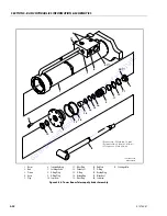
Clamp barrel (1) securely and support rod (2). Insert pis-
ton in cylinder. Do not damage or dislodge piston load-
ing O-ring and seal ring.
17.
Continue pushing rod into cylinder until cylinder head
assembly (3) can be inserted into cylinder.
18.
Align marks made during disassembly.
19.
Apply locking primer (JLG PN 0100038) and Medium
Strength Threadlocking Compound to eight socket
head bolts (9).
20.
Secure cylinder head and washer ring (10) if applicable
with socket head Capscrew (9).
Figure 5-39. Rod Assembly Installation
Rod
Piston
Tapered
Bushing
Rod
Capscrew
Tapered Bushing
3/4in (19mm) Brass Drift
16-24oz (454-680g) Hammer
Figure 5-38. Seating Tapered Bushing
1
2
9
10
3
Go
to
Discount-Equipment.com
to
order
your
parts


