


SECTION 3 - CHASSIS & TURNTABLE
3-36
– JLG Lift –
3121290
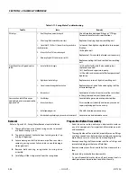
Oscillating Axle Lockout Test
LOCKOUT SYSTEM TEST MUST BE PERFORMED QUARTERLY, ANY TIME A SYS-
TEM COMPONENT IS REPLACED, OR WHEN IMPROPER SYSTEM OPERATION IS
SUSPECTED.
NOTE:
Ensure boom is fully retracted, lowered, and centered
between drive wheels before starting lockout cylinder test.
1.
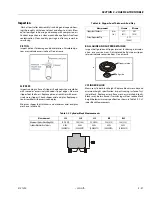
Place a 6" (15 cm) high block with ascension ramp in
front of left front wheel.
2.
From platform control station, activate machine hydrau-
lic system.
3.
Place FUNCTION SPEED CONTROL and DRIVE SPEED/
TORQUE SELECT control switches to LOW positions.
4.
Place DRIVE control lever to FORWARD position and
carefully drive machine up ascension ramp until left
front wheel is on top of block.
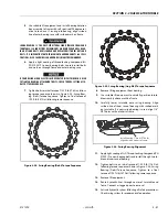
5.
Carefully activate SWING control lever and position
boom over right side of machine.
6.
With boom over right side of machine, place DRIVE con-
trol lever to REVERSE. Drive machine off block and ramp.
7.
Have an assistant check to see left front wheel remains
locked in position off of ground.
8.
Carefully activate SWING control lever and return boom
to stowed position (centered between drive wheels).
When boom reaches center, stowed position, lockout cyl-
inders should release and allow wheel to rest on ground.
It may be necessary activate DRIVE to release cylinders.
9.
Place 6" (15 cm) high block with ascension ramp in front
of right front wheel.
10.
Place DRIVE control lever to FORWARD. Carefully drive
machine up ramp until right front wheel is on top of
block.
11.
Carefully activate SWING control lever and position
boom over left side of machine.
12.
With boom over left side of machine, place DRIVE con-
trol lever to REVERSE. Drive machine off block and ramp.
13.
Have an assistant check to see that right front wheel
remains locked in position off ground.
14.
Carefully activate SWING control lever and return boom
to stowed position (centered between drive wheels).
When boom reaches center, stowed position, lockout
cylinders should release and allow wheel to rest on
ground. It may be necessary activate DRIVE to release
cylinders.
15.
If lockout cylinders do not function properly, have qualified
personnel correct malfunction before further operation.
3.7
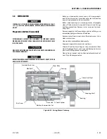
SWING BEARING
Description
The swing bearing has five major components: housing,
worm, worm gear, output pinion, and gear/pinion cap.
Servicing these units requires a press, a 3/8" 12 point socket, a
1/2" socket, a 3/4" socket, torque wrench (80 ft-lb), steel ham-
mer, soft face hammer, bearing puller (external and internal),
and a large flat blade screw driver. Also needed are a shim and
seal kit (refer to JLG Parts Manual), 3/4" steel rod at least 10"
long, silicone sealant Mobil SHC 460 grease, Lubriplate No.
930-AAA, JLG Threadlocker PN 0100011 for bolts, and other
parts that may be worn out.
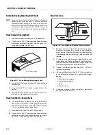
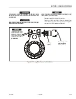
Removal
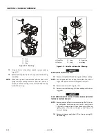
Refer to Figure 3-31., Swing Bearing Installation.
1.
Attach an adequate support sling to boom and draw all
slack from sling. Prop or block boom if possible.
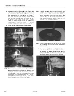
2.
Tag and disconnect hydraulic lines running through
center of turntable (1) and frame (2). Use a suitable con-
tainer catch residual hydraulic fluid. Cap lines and ports.
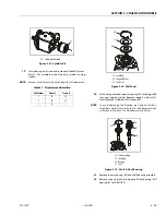
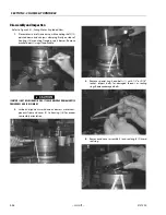
1.
Clean area around swing motor (3) to prevent any dirt
from entering system.
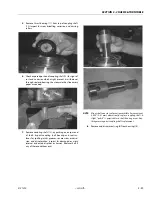
2.
Tag and disconnect hydraulic lines running to swing
motor. Cap or plug all openings.
3.
Attach suitable overhead lifting equipment to base of
turntable weldment (1).
4.
Scribe a line on inner race of swing bearing (4) and
underside of turntable to help align bearing during
installation. Remove bolts (5) and washers (6) from turn-
table and bearing inner race. Discard bolts.
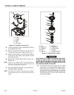
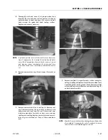
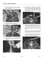
5.
Use lifting equipment to lift complete turntable assem-
bly from bearing. Ensure no damage occurs to turntable,
bearing, or frame components. Carefully place turntable
on a suitably supported trestle.
6.
Scribe a line on outer race of swing bearing and frame to
help align bearing during installation.
7.
Remove bolts (7) and washers (8) from outer race of
bearing to frame. Discard bolts.
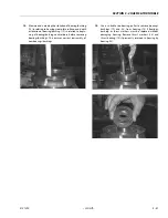
8.
Use suitable lifting equipment to remove bearing and
rotation box assembly from frame. Move to a clean, suit-
ably supported work area.
Содержание 450A II Series
Страница 21: ...SECTION 1 SPECIFICATIONS 3121290 JLG Lift 1 5 Figure 1 2 Operator Maintenance and Lubrication Diagram ...
Страница 44: ...SECTION 3 CHASSIS TURNTABLE 3 4 JLG Lift 3121290 Figure 3 3 Drive Hub and Brake Assembly 2WD and 4WD ...
Страница 46: ...SECTION 3 CHASSIS TURNTABLE 3 6 JLG Lift 3121290 Figure 3 4 Drive Hub 4WD Front Only ...
Страница 79: ...SECTION 3 CHASSIS TURNTABLE 3121290 JLG Lift 3 39 Figure 3 32 Swing Bearing Drive ...
Страница 101: ...SECTION 3 CHASSIS TURNTABLE 3121290 JLG Lift 3 61 Figure 3 42 Auxiliary Pump ...
Страница 107: ...SECTION 3 CHASSIS TURNTABLE 3121290 JLG Lift 3 67 Figure 3 47 Deutz EMR 2 Troubleshooting Flow Chart ...
Страница 108: ...SECTION 3 CHASSIS TURNTABLE 3 68 JLG Lift 3121290 Figure 3 48 Deutz EMR 2 Vehicle Side Connection Diagram ...
Страница 109: ...SECTION 3 CHASSIS TURNTABLE 3121290 JLG Lift 3 69 Figure 3 49 Deutz EMR 2 Engine Side Connection Diagram Sheet 1 of 2 ...
Страница 110: ...SECTION 3 CHASSIS TURNTABLE 3 70 JLG Lift 3121290 Figure 3 50 Deutz EMR 2 Engine Side Connection Diagram Sheet 2 of 2 ...
Страница 111: ...SECTION 3 CHASSIS TURNTABLE 3121290 JLG Lift 3 71 Figure 3 51 EMR 2 Engine Plug Pin Identification ...
Страница 112: ...SECTION 3 CHASSIS TURNTABLE 3 72 JLG Lift 3121290 Figure 3 52 EMR 2 Vehicle Plug Pin Identification ...
Страница 113: ...SECTION 3 CHASSIS TURNTABLE 3121290 JLG Lift 3 73 Figure 3 53 EMR2 Fault Codes Sheet 1 of 5 ...
Страница 114: ...SECTION 3 CHASSIS TURNTABLE 3 74 JLG Lift 3121290 Figure 3 54 EMR2 Fault Codes Sheet 2 of 5 ...
Страница 115: ...SECTION 3 CHASSIS TURNTABLE 3121290 JLG Lift 3 75 Figure 3 55 EMR2 Fault Codes Sheet 3 of 5 ...
Страница 116: ...SECTION 3 CHASSIS TURNTABLE 3 76 JLG Lift 3121290 Figure 3 56 EMR2 Fault Codes Sheet 4 of 5 ...
Страница 117: ...SECTION 3 CHASSIS TURNTABLE 3121290 JLG Lift 3 77 Figure 3 57 EMR2 Fault Codes Sheet 5 of 5 ...
Страница 159: ...SECTION 3 CHASSIS TURNTABLE 3121290 JLG Lift 3 119 ...
Страница 161: ...SECTION 3 CHASSIS TURNTABLE 3121290 JLG Lift 3 121 ...
Страница 163: ...SECTION 3 CHASSIS TURNTABLE 3121290 JLG Lift 3 123 ...
Страница 165: ...SECTION 3 CHASSIS TURNTABLE 3121290 JLG Lift 3 125 ...
Страница 173: ...SECTION 3 CHASSIS TURNTABLE 3121290 JLG Lift 3 133 Sensor Transducer Type ...
Страница 177: ...SECTION 3 CHASSIS TURNTABLE 3121290 JLG Lift 3 137 Sensor Transducer Type ...
Страница 179: ...SECTION 3 CHASSIS TURNTABLE 3121290 JLG Lift 3 139 ...
Страница 181: ...SECTION 3 CHASSIS TURNTABLE 3121290 JLG Lift 3 141 ...
Страница 183: ...SECTION 3 CHASSIS TURNTABLE 3121290 JLG Lift 3 143 ...
Страница 185: ...SECTION 3 CHASSIS TURNTABLE 3121290 JLG Lift 3 145 ...
Страница 187: ...SECTION 3 CHASSIS TURNTABLE 3121290 JLG Lift 3 147 ...
Страница 203: ...SECTION 3 CHASSIS TURNTABLE 3121290 JLG Lift 3 163 ...
Страница 207: ...SECTION 3 CHASSIS TURNTABLE 3121290 JLG Lift 3 167 ...
Страница 217: ...SECTION 4 BOOM PLATFORM 3121290 JLG Lift 4 5 Figure 4 2 Boom Limit Switches ...
Страница 310: ...SECTION 5 HYDRAULICS 5 70 JLG Lift 3121290 NOTES ...
Страница 312: ...SECTION 6 JLG CONTROL SYSTEM 6 2 JLG Lift 3121290 Figure 6 2 Controller Block Diagram 0 ...
Страница 337: ...SECTION 6 JLG CONTROL SYSTEM 3121290 JLG Lift 6 27 Figure 6 11 System Test Flow Chart Platform Tests ...
Страница 339: ...SECTION 6 JLG CONTROL SYSTEM 3121290 JLG Lift 6 29 Figure 6 12 System Test Flow Chart Ground Station Tests ...
Страница 350: ...SECTION 6 JLG CONTROL SYSTEM 6 40 JLG Lift 3121290 Figure 6 13 Control Module And Fault Code Light Locations ...
Страница 370: ...SECTION 6 JLG CONTROL SYSTEM 6 60 JLG Lift 3121290 NOTES ...
Страница 380: ...SECTION 7 BASIC ELECTRICAL INFORMATION SCHEMATICS 7 10 JLG Lift 3121290 Figure 7 26 Electrical Components 1 of 2 ...
Страница 381: ...SECTION 7 BASIC ELECTRICAL INFORMATION SCHEMATICS 3121290 JLG Lift 7 11 Figure 7 27 Electrical Components 2 of 2 ...
Страница 388: ...SECTION 7 BASIC ELECTRICAL INFORMATION SCHEMATICS 7 18 JLG Lift 3121290 Figure 7 34 Main Hydraulic Schematic 1 of 2 ...
Страница 394: ...SECTION 7 BASIC ELECTRICAL INFORMATION SCHEMATICS 7 24 JLG Lift 3121290 NOTES ...
Страница 395: ......