


SECTION 3 - CHASSIS & TURNTABLE
3-86
– JLG Lift –
3121290
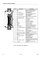
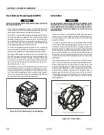
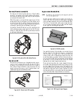
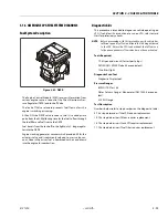
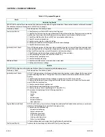
Heated Exhaust Gas Oxygen Sensor
There are two Heated Exhaust Gas Oxygen Sensors (HEGO).
The first HEGO is mounted in the exhaust system downstream
of the engine. It is used to measure the amount of oxygen
present in the exhaust stream and communicate that to the
ECM via an electrical signal. The amount of oxygen present in
the exhaust stream indicates whether the fuel/air ratio is too
rich or too lean. If the HEGO sensor signal indicates exhaust
stream is too rich, the ECM will decrease or lean the fuel mix-
ture during engine operation. If mixture is too lean the ECM
will richen the mixture. The ECM continuously monitors the
HEGO sensor output. If a rich or lean condition is present for an
extended period of time, and the ECM cannot correct the con-
dition, the ECM sets a diagnostic code and turns on the MIL
light in control box.
The second HEGO is mounted in the exhaust system after the
muffler. It measures the amount of oxygen in the exhaust sys-
tem after the catalyst treatment has been completed in the
muffler. If the ECM detects that the catalytic action in the muf-
fler is not sufficient and fuel correction cannot correct the mal-
function the MIL light is illuminated in the control box and a
DTC code will stored in the computer.
THE HEATED EXHAUST GAS OXYGEN SENSOR IS AN EMISSION CONTROL
DEVICE. IF THE HEGO FAILS TO OPERATE, REPLACE IT WITH AN OEM REPLACE-
MENT PART. THE HEGO SENSOR IS SENSITIVE TO SILICONE OR SILICONE
BASED PRODUCTS AND CAN BECOME CONTAMINATED. AVOID USING SILICONE
SEALERS OR HOSES TREATED WITH SILICONE LUBRICANTS IN THE AIR
STREAM OR FUEL LINES.
Gasoline Multi Point Fuel Injection System (MPFI)
The primary components of the Gasoline Multi Point Fuel
Injection (MPFI) fuel system are the fuel tank, electric fuel
pump, fuel pressure and temperature sensor manifold, fuel fil-
ter, and fuel rail.
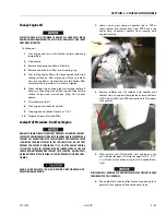
Gasoline Fuel Pump
Gasoline is stored as a liquid in the fuel tank and in drawn into
the fuel system by an electric fuel pump. The fuel pump
receives a signal from the ECM to prime the fuel system for
approximately 2 seconds before start. Priming the fuel system
provides for a quicker start when engine begins to crank.
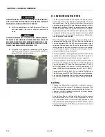
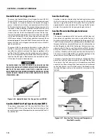
Gasoline Pressure And Temperature Sensor
Manifold
This engine is equipped with a fuel injector rail that does not
have a pressure regulator or a return circuit to the fuel tank.
Fuel pressure for this engine is regulated by the engine’s ECM.
The ECM receive fuel pressure and temperature feedback from
the gasoline fuel sensor manifold and uses this information to
control the ground side of the fuel pump. Fuel pressure is reg-
ulated by the ECM pulse width modulating (PWM) the fuel
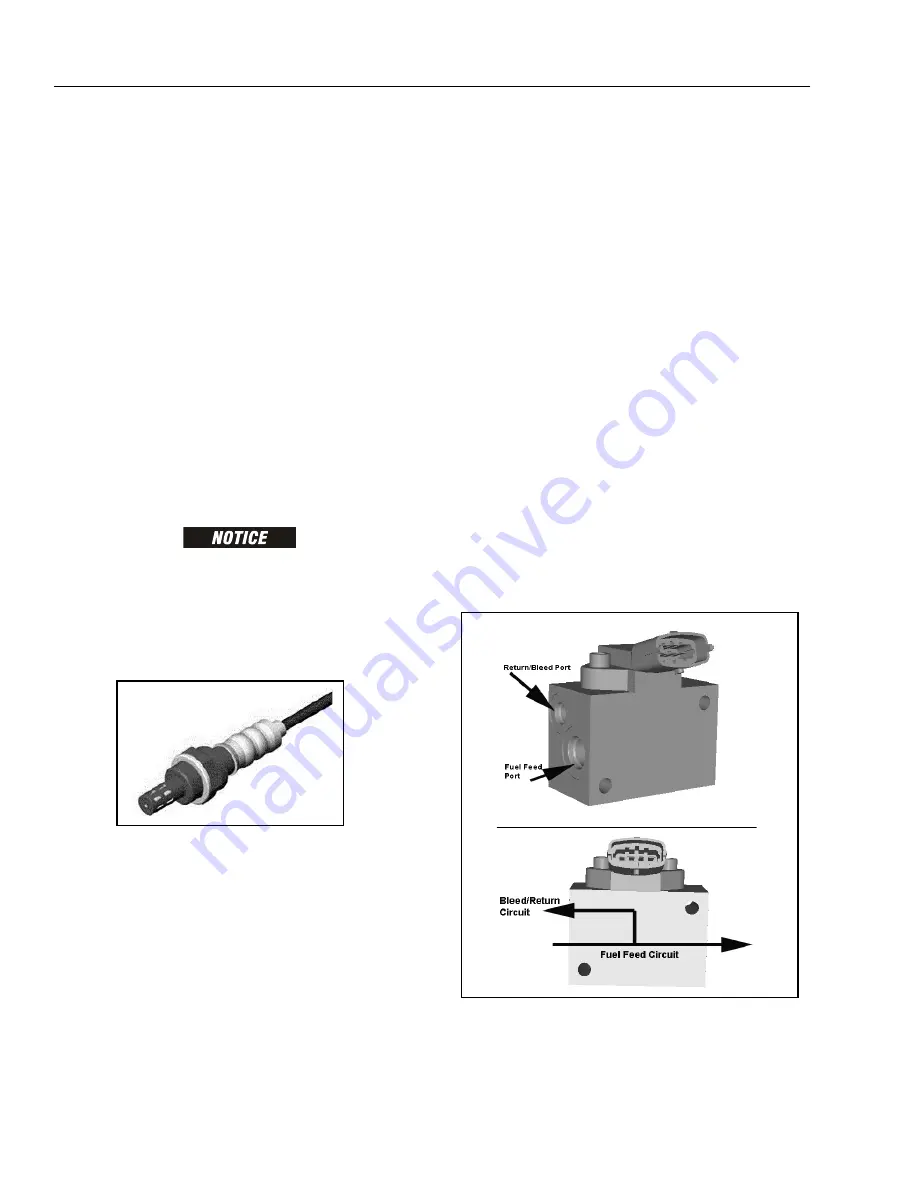
pump. The fuel pressure and temperature sensor manifold has
a return or "bleed" circuit that connects back to the fuel tank.
This circuit is used to bleed off any vapor that develops in the
line and return a small amount of fuel to the tank.
Fuel comes from the fuel tank and passes through the fuel
pump. Fuel exits the fuel pump, passes through the filter and
then enters the fuel pressure and temperature manifold
assembly. Fuel flows through the feed circuit and is delivered
to the fuel injector rail. Fuel that enters the bleed circuits
through the bypass valve in the manifold is returned to the
fuel tank.
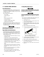
Figure 3-66. Heated Exhaust Gas Oxygen Sensor (HEGO)
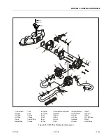
Figure 3-67. Gasoline Fuel Pressure and Temperature
Manifold Assembly
Содержание 450A II Series
Страница 21: ...SECTION 1 SPECIFICATIONS 3121290 JLG Lift 1 5 Figure 1 2 Operator Maintenance and Lubrication Diagram ...
Страница 44: ...SECTION 3 CHASSIS TURNTABLE 3 4 JLG Lift 3121290 Figure 3 3 Drive Hub and Brake Assembly 2WD and 4WD ...
Страница 46: ...SECTION 3 CHASSIS TURNTABLE 3 6 JLG Lift 3121290 Figure 3 4 Drive Hub 4WD Front Only ...
Страница 79: ...SECTION 3 CHASSIS TURNTABLE 3121290 JLG Lift 3 39 Figure 3 32 Swing Bearing Drive ...
Страница 101: ...SECTION 3 CHASSIS TURNTABLE 3121290 JLG Lift 3 61 Figure 3 42 Auxiliary Pump ...
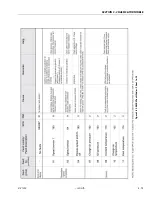
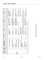
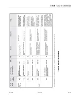
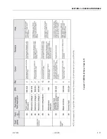
Страница 107: ...SECTION 3 CHASSIS TURNTABLE 3121290 JLG Lift 3 67 Figure 3 47 Deutz EMR 2 Troubleshooting Flow Chart ...
Страница 108: ...SECTION 3 CHASSIS TURNTABLE 3 68 JLG Lift 3121290 Figure 3 48 Deutz EMR 2 Vehicle Side Connection Diagram ...
Страница 109: ...SECTION 3 CHASSIS TURNTABLE 3121290 JLG Lift 3 69 Figure 3 49 Deutz EMR 2 Engine Side Connection Diagram Sheet 1 of 2 ...
Страница 110: ...SECTION 3 CHASSIS TURNTABLE 3 70 JLG Lift 3121290 Figure 3 50 Deutz EMR 2 Engine Side Connection Diagram Sheet 2 of 2 ...
Страница 111: ...SECTION 3 CHASSIS TURNTABLE 3121290 JLG Lift 3 71 Figure 3 51 EMR 2 Engine Plug Pin Identification ...
Страница 112: ...SECTION 3 CHASSIS TURNTABLE 3 72 JLG Lift 3121290 Figure 3 52 EMR 2 Vehicle Plug Pin Identification ...
Страница 113: ...SECTION 3 CHASSIS TURNTABLE 3121290 JLG Lift 3 73 Figure 3 53 EMR2 Fault Codes Sheet 1 of 5 ...
Страница 114: ...SECTION 3 CHASSIS TURNTABLE 3 74 JLG Lift 3121290 Figure 3 54 EMR2 Fault Codes Sheet 2 of 5 ...
Страница 115: ...SECTION 3 CHASSIS TURNTABLE 3121290 JLG Lift 3 75 Figure 3 55 EMR2 Fault Codes Sheet 3 of 5 ...
Страница 116: ...SECTION 3 CHASSIS TURNTABLE 3 76 JLG Lift 3121290 Figure 3 56 EMR2 Fault Codes Sheet 4 of 5 ...
Страница 117: ...SECTION 3 CHASSIS TURNTABLE 3121290 JLG Lift 3 77 Figure 3 57 EMR2 Fault Codes Sheet 5 of 5 ...
Страница 159: ...SECTION 3 CHASSIS TURNTABLE 3121290 JLG Lift 3 119 ...
Страница 161: ...SECTION 3 CHASSIS TURNTABLE 3121290 JLG Lift 3 121 ...
Страница 163: ...SECTION 3 CHASSIS TURNTABLE 3121290 JLG Lift 3 123 ...
Страница 165: ...SECTION 3 CHASSIS TURNTABLE 3121290 JLG Lift 3 125 ...
Страница 173: ...SECTION 3 CHASSIS TURNTABLE 3121290 JLG Lift 3 133 Sensor Transducer Type ...
Страница 177: ...SECTION 3 CHASSIS TURNTABLE 3121290 JLG Lift 3 137 Sensor Transducer Type ...
Страница 179: ...SECTION 3 CHASSIS TURNTABLE 3121290 JLG Lift 3 139 ...
Страница 181: ...SECTION 3 CHASSIS TURNTABLE 3121290 JLG Lift 3 141 ...
Страница 183: ...SECTION 3 CHASSIS TURNTABLE 3121290 JLG Lift 3 143 ...
Страница 185: ...SECTION 3 CHASSIS TURNTABLE 3121290 JLG Lift 3 145 ...
Страница 187: ...SECTION 3 CHASSIS TURNTABLE 3121290 JLG Lift 3 147 ...
Страница 203: ...SECTION 3 CHASSIS TURNTABLE 3121290 JLG Lift 3 163 ...
Страница 207: ...SECTION 3 CHASSIS TURNTABLE 3121290 JLG Lift 3 167 ...
Страница 217: ...SECTION 4 BOOM PLATFORM 3121290 JLG Lift 4 5 Figure 4 2 Boom Limit Switches ...
Страница 310: ...SECTION 5 HYDRAULICS 5 70 JLG Lift 3121290 NOTES ...
Страница 312: ...SECTION 6 JLG CONTROL SYSTEM 6 2 JLG Lift 3121290 Figure 6 2 Controller Block Diagram 0 ...
Страница 337: ...SECTION 6 JLG CONTROL SYSTEM 3121290 JLG Lift 6 27 Figure 6 11 System Test Flow Chart Platform Tests ...
Страница 339: ...SECTION 6 JLG CONTROL SYSTEM 3121290 JLG Lift 6 29 Figure 6 12 System Test Flow Chart Ground Station Tests ...
Страница 350: ...SECTION 6 JLG CONTROL SYSTEM 6 40 JLG Lift 3121290 Figure 6 13 Control Module And Fault Code Light Locations ...
Страница 370: ...SECTION 6 JLG CONTROL SYSTEM 6 60 JLG Lift 3121290 NOTES ...
Страница 380: ...SECTION 7 BASIC ELECTRICAL INFORMATION SCHEMATICS 7 10 JLG Lift 3121290 Figure 7 26 Electrical Components 1 of 2 ...
Страница 381: ...SECTION 7 BASIC ELECTRICAL INFORMATION SCHEMATICS 3121290 JLG Lift 7 11 Figure 7 27 Electrical Components 2 of 2 ...
Страница 388: ...SECTION 7 BASIC ELECTRICAL INFORMATION SCHEMATICS 7 18 JLG Lift 3121290 Figure 7 34 Main Hydraulic Schematic 1 of 2 ...
Страница 394: ...SECTION 7 BASIC ELECTRICAL INFORMATION SCHEMATICS 7 24 JLG Lift 3121290 NOTES ...
Страница 395: ......