


SECTION 3 - CHASSIS & TURNTABLE
3-80
– JLG Lift –
3121290
3.13 GM ENGINE GENERAL MAINTENANCE
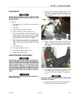
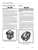
Drive Belt Maintenance
The serpentine drive belt utilizes a spring loaded tensioner
which keeps the belt properly adjusted. The drive belt is an
integral part of the cooling and charging systems and should
be inspected frequently.
When inspecting the belts check for:
• Cracks or breaks
• Chunking of the belt
• Splits
• Material hanging from the belt
• Glazing and hardening
• Damaged or improperly aligned pulleys
• Improperly performing tensioner
Check belt tensioner by pressing down on midway point of
the longest stretch between pulleys. The belt should not
depress beyond 1/2 inch (13mm). Adjust tension if depression
is more than allowable,
ENGINE MANUFACTURER DOES NOT RECOMMEND USE OF “BELT DRESSING”
OR “ANTI SLIPPING AGENTS” ON DRIVE BELT.
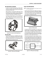
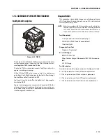
Engine Electrical System Maintenance
The engine electrical system uses computers and micropro-
cessors to control engine ignition, fuel control, and emissions.
Periodic inspection of electrical wiring is required due to sensi-
tivity of computers to good electrical connections. When
inspecting electrical system:
• Check and clean battery terminal connections and ensure
connections are tight.
• Check battery for any cracks or damage to the case.
• Check positive and negative battery cables for corrosion,
rubbing, or chafing. Check connection to chassis is tight.
• Check entire engine wire harness for rubbing chafing, cuts,
or damaged connections. Repair as needed.
• Check all wire harness connectors are fully seated and
locked.
• Check ignition coil and spark plug cables for hardening,
cracking, chafing, separation, split boot covers and
proper fit.
• Replace spark plugs at the proper intervals as prescribed in
the engine manufacturer’s manual.
• Make sure all electrical components are fitted securely.
• Check ground and platform control stations to ensure all
warning indicator lights are functioning.
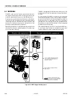
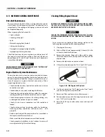
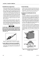
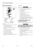
Checking/Filling Engine Oil Level
AN OVERFILLED CRANKCASE (OIL LEVEL OVER THE SPECIFIED FULL MARK)
CAN CAUSE AN OIL LEAK, A FLUCTUATION OR DROP IN THE OIL PRESSURE,
AND ROCKER ARM “CLATTER” IN THE ENGINE.
CARE MUST BE TAKEN WHEN CHECKING THE ENGINE OIL LEVEL. OIL LEVEL
MUST BE MAINTAINED BETWEEN THE “ADD” MARK AND “FULL” MARK ON THE
DIPSTICK.
To ensure you are not getting a false reading, make sure the
following steps are taken before checking oil level.
1.
Stop engine if running.
2.
Allow sufficient time (approximately 5 minutes) for the
oil to drain back into the oil pan.
3.
Remove the dipstick. Wipe with a clean cloth or paper
towel and reinstall. Push the dipstick all the way into the
dipstick tube.
4.
Remove the dipstick and note the oil level.
5.
Oil level must be between the “FULL” and “ADD” marks.
Figure 3-58. GM Engine Oil Dip Stick
6.
If oil level is below the “ADD” mark, go to Step 7 and 8
and reinstall dipstick in dipstick tube.
7.
Remove oil filter cap from valve rocker arm cover.
8.
Add required amount of oil to bring level up to, but not
over, “FULL” mark on dipstick.
9.
Reinstall oil fill cap to valve rocker cover and wipe off
excess oil.
Содержание 450A II Series
Страница 21: ...SECTION 1 SPECIFICATIONS 3121290 JLG Lift 1 5 Figure 1 2 Operator Maintenance and Lubrication Diagram ...
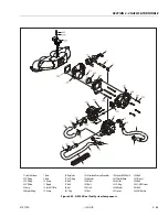
Страница 44: ...SECTION 3 CHASSIS TURNTABLE 3 4 JLG Lift 3121290 Figure 3 3 Drive Hub and Brake Assembly 2WD and 4WD ...
Страница 46: ...SECTION 3 CHASSIS TURNTABLE 3 6 JLG Lift 3121290 Figure 3 4 Drive Hub 4WD Front Only ...
Страница 79: ...SECTION 3 CHASSIS TURNTABLE 3121290 JLG Lift 3 39 Figure 3 32 Swing Bearing Drive ...
Страница 101: ...SECTION 3 CHASSIS TURNTABLE 3121290 JLG Lift 3 61 Figure 3 42 Auxiliary Pump ...
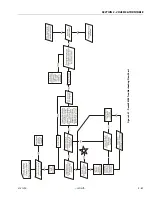
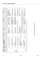
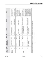
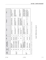
Страница 107: ...SECTION 3 CHASSIS TURNTABLE 3121290 JLG Lift 3 67 Figure 3 47 Deutz EMR 2 Troubleshooting Flow Chart ...
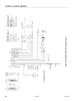
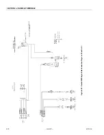
Страница 108: ...SECTION 3 CHASSIS TURNTABLE 3 68 JLG Lift 3121290 Figure 3 48 Deutz EMR 2 Vehicle Side Connection Diagram ...
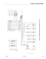
Страница 109: ...SECTION 3 CHASSIS TURNTABLE 3121290 JLG Lift 3 69 Figure 3 49 Deutz EMR 2 Engine Side Connection Diagram Sheet 1 of 2 ...
Страница 110: ...SECTION 3 CHASSIS TURNTABLE 3 70 JLG Lift 3121290 Figure 3 50 Deutz EMR 2 Engine Side Connection Diagram Sheet 2 of 2 ...
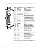
Страница 111: ...SECTION 3 CHASSIS TURNTABLE 3121290 JLG Lift 3 71 Figure 3 51 EMR 2 Engine Plug Pin Identification ...
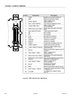
Страница 112: ...SECTION 3 CHASSIS TURNTABLE 3 72 JLG Lift 3121290 Figure 3 52 EMR 2 Vehicle Plug Pin Identification ...
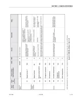
Страница 113: ...SECTION 3 CHASSIS TURNTABLE 3121290 JLG Lift 3 73 Figure 3 53 EMR2 Fault Codes Sheet 1 of 5 ...
Страница 114: ...SECTION 3 CHASSIS TURNTABLE 3 74 JLG Lift 3121290 Figure 3 54 EMR2 Fault Codes Sheet 2 of 5 ...
Страница 115: ...SECTION 3 CHASSIS TURNTABLE 3121290 JLG Lift 3 75 Figure 3 55 EMR2 Fault Codes Sheet 3 of 5 ...
Страница 116: ...SECTION 3 CHASSIS TURNTABLE 3 76 JLG Lift 3121290 Figure 3 56 EMR2 Fault Codes Sheet 4 of 5 ...
Страница 117: ...SECTION 3 CHASSIS TURNTABLE 3121290 JLG Lift 3 77 Figure 3 57 EMR2 Fault Codes Sheet 5 of 5 ...
Страница 159: ...SECTION 3 CHASSIS TURNTABLE 3121290 JLG Lift 3 119 ...
Страница 161: ...SECTION 3 CHASSIS TURNTABLE 3121290 JLG Lift 3 121 ...
Страница 163: ...SECTION 3 CHASSIS TURNTABLE 3121290 JLG Lift 3 123 ...
Страница 165: ...SECTION 3 CHASSIS TURNTABLE 3121290 JLG Lift 3 125 ...
Страница 173: ...SECTION 3 CHASSIS TURNTABLE 3121290 JLG Lift 3 133 Sensor Transducer Type ...
Страница 177: ...SECTION 3 CHASSIS TURNTABLE 3121290 JLG Lift 3 137 Sensor Transducer Type ...
Страница 179: ...SECTION 3 CHASSIS TURNTABLE 3121290 JLG Lift 3 139 ...
Страница 181: ...SECTION 3 CHASSIS TURNTABLE 3121290 JLG Lift 3 141 ...
Страница 183: ...SECTION 3 CHASSIS TURNTABLE 3121290 JLG Lift 3 143 ...
Страница 185: ...SECTION 3 CHASSIS TURNTABLE 3121290 JLG Lift 3 145 ...
Страница 187: ...SECTION 3 CHASSIS TURNTABLE 3121290 JLG Lift 3 147 ...
Страница 203: ...SECTION 3 CHASSIS TURNTABLE 3121290 JLG Lift 3 163 ...
Страница 207: ...SECTION 3 CHASSIS TURNTABLE 3121290 JLG Lift 3 167 ...
Страница 217: ...SECTION 4 BOOM PLATFORM 3121290 JLG Lift 4 5 Figure 4 2 Boom Limit Switches ...
Страница 310: ...SECTION 5 HYDRAULICS 5 70 JLG Lift 3121290 NOTES ...
Страница 312: ...SECTION 6 JLG CONTROL SYSTEM 6 2 JLG Lift 3121290 Figure 6 2 Controller Block Diagram 0 ...
Страница 337: ...SECTION 6 JLG CONTROL SYSTEM 3121290 JLG Lift 6 27 Figure 6 11 System Test Flow Chart Platform Tests ...
Страница 339: ...SECTION 6 JLG CONTROL SYSTEM 3121290 JLG Lift 6 29 Figure 6 12 System Test Flow Chart Ground Station Tests ...
Страница 350: ...SECTION 6 JLG CONTROL SYSTEM 6 40 JLG Lift 3121290 Figure 6 13 Control Module And Fault Code Light Locations ...
Страница 370: ...SECTION 6 JLG CONTROL SYSTEM 6 60 JLG Lift 3121290 NOTES ...
Страница 380: ...SECTION 7 BASIC ELECTRICAL INFORMATION SCHEMATICS 7 10 JLG Lift 3121290 Figure 7 26 Electrical Components 1 of 2 ...
Страница 381: ...SECTION 7 BASIC ELECTRICAL INFORMATION SCHEMATICS 3121290 JLG Lift 7 11 Figure 7 27 Electrical Components 2 of 2 ...
Страница 388: ...SECTION 7 BASIC ELECTRICAL INFORMATION SCHEMATICS 7 18 JLG Lift 3121290 Figure 7 34 Main Hydraulic Schematic 1 of 2 ...
Страница 394: ...SECTION 7 BASIC ELECTRICAL INFORMATION SCHEMATICS 7 24 JLG Lift 3121290 NOTES ...
Страница 395: ......