SECTION 3 - CHASSIS & SCISSOR ARMS
3121273
– JLG Lift –
3-13
Tilt Sensor Removal
1. Disconnect power at the batteries.
2. Remove the machine left side cover (ground control
station side).
3. Unplug the tilt sensor 3-wire harness connector.
4. Remove the two (2) mounting nuts, bolts and wash-
ers attaching the sensor to the base frame.
Tilt Sensor Installation
1. Before mounting the tilt sensor to the base frame,
check the mating surfaces of the sensor and the
mounting plate, be certain there is no debris or burrs
to prevent a flush mount.
2. When mounting the tilt sensor back into the base
frame, align the mounting pin on the bottom of the
sensor with the hole in the mounting plate on the
base frame
(item 2 - Figure 3-16.)
.
3. Secure to the base frame with the mounting hard-
ware.
4. Adjust per instructions following.
Tilt Sensor Switch - Adjustment Procedure
NOTICE
PERFORM TILT SWITCH LEVELING PROCEDURE A MINIMUM OF
EVERY SIX MONTHS TO ENSURE PROPER OPERATION AND
ADJUSTMENT OF SWITCH.
1. Park the machine on a smooth, firm, and level sur-
face. Be sure it is as level as possible.
NOTE:
Ensure switch mounting is level and securely
attached.
2. Tighten the three flange nuts with a socket wrench.
Each nut should be tightened approximately one-
quarter of its spring’s travel.
3. Using bubble level on top of indicator, Tighten or
loosen the three flange nuts until indicator is level.
4. Individually push down on one corner at a time.
There should be enough travel to cause the indica-
tor to trip. If the indicator does not trip in all three
tests, the flange nuts have been tightened too far.
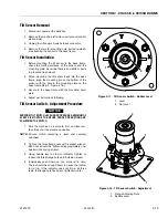
Figure 3-17. Tilt Sensor Switch - Bubble Level
1. Level
2. Not Level
Figure 3-18. Tilt Sensor Switch - Adjustment
1. Flange Adjusting Nuts
2. Bubble Level
1
2
1
1
1
2
Содержание 1932RS
Страница 1: ...Service Maintenance Manual Models 1932RS 6RS 3248RS 10RS 3121273 April 8 2013...
Страница 2: ......
Страница 12: ...viii JLG Lift 3121273 TABLE OF CONTENTS NOTES...
Страница 69: ...SECTION 3 CHASSIS SCISSOR ARMS 3121273 JLG Lift 3 37 NOTES...
Страница 73: ...SECTION 3 CHASSIS SCISSOR ARMS 3121273 JLG Lift 3 41 Figure 3 41 Arms and Platform Positioning and Support...


