


SECTION 2 - USER RESPONSIBILITIES, MACHINE PREPARATION, AND INSPECTION
2-16
– JLG Lift –
3121261
2.3
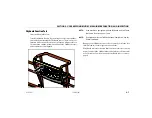
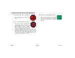
OSCILLATING AXLE LOCKOUT TEST (IF EQUIPPED)
The front axles will oscillate when the boom is in the transport posi-
tion (i.e. when the boom is less than 6° above horizontal and not
extended beyond 12" [30.4 cm]) and drive is selected.
LOCKOUT SYSTEM TEST MUST BE PERFORMED QUARTERLY, ANY TIME A SYSTEM COM-
PONENT IS REPLACED, OR WHEN IMPROPER SYSTEM OPERATION IS SUSPECTED.
NOTE:
Ensure the axles are extended and the boom is fully retracted,
lowered, and centered between the rear wheels prior to begin-
ning lockout cylinder test.
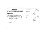
1.
Place a 6 inches (15.2 cm) high block with ascension ramp in
front of left front wheel.
2.
From platform control station, start engine.
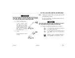
3.
Place the Drive control lever to the forward position and
carefully drive machine up ascension ramp until left front
wheel is on top of block.
4.
Carefully extend the boom just enough to get it out of the
transport position.
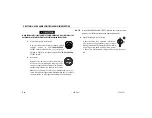
5.
With boom in this position, place Drive control lever to
Reverse and carefully drive machine off of block and ramp.
6.
Have an assistant check to see that left front or right rear
wheel remains elevated in position off of the ground.
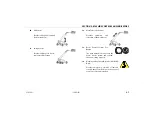
7.
Carefully return the boom to the transport position. When
boom reaches the transport position, carefully activate Drive
to release cylinders. The lockout cylinders should release
and allow the wheel to rest on ground.
8.
Repeat the procedure for the right oscillation cylinder check-
ing to see that the right front or left rear wheel remains ele-
vated in position off of the ground.
9.
If lockout cylinders do not function properly, have qualified
personnel correct the malfunction prior to any further oper-
ation.
Содержание 1500SJ
Страница 2: ......
Страница 28: ...SECTION 1 SAFETY PRECAUTIONS 1 14 JLG Lift 3121261 NOTES ...
Страница 68: ...SECTION 3 MACHINE CONTROLS AND INDICATORS 3 24 JLG Lift 3121261 NOTES ...
Страница 94: ...SECTION 4 MACHINE OPERATION 4 26 JLG Lift 3121261 37 37 10 34 Figure 4 11 Decal Location Sheet 5 of 6 ...
Страница 100: ...SECTION 4 MACHINE OPERATION 4 32 JLG Lift 3121261 NOTES ...
Страница 143: ...SECTION 5 LCD DISPLAY PANEL GENERATION 1 2 3121261 JLG Lift 5 43 Figure 5 29 BCS Lamp Screen ...
Страница 149: ...SECTION 5 LCD DISPLAY PANEL GENERATION 1 2 3121261 JLG Lift 5 49 Figure 5 34 Swing DTC Screen ...
Страница 157: ...SECTION 5 LCD DISPLAY PANEL GENERATION 1 2 3121261 JLG Lift 5 57 Figure 5 40 Unrestricted Mode Screen ...
Страница 158: ...SECTION 5 LCD DISPLAY PANEL GENERATION 1 2 5 58 JLG Lift 3121261 Figure 5 41 Restricted Mode Screen ...
Страница 166: ...SECTION 6 EMERGENCY PROCEDURES 6 4 JLG Lift 3121261 NOTES ...
Страница 180: ...SECTION 7 ACCESSORIES 7 14 JLG Lift 3121261 NOTES ...
Страница 189: ...SECTION 8 GENERAL SPECIFICATIONS OPERATOR MAINTENANCE 3121261 JLG Lift 8 9 Figure 8 1 Oil Sampling Port ...
Страница 208: ...SECTION 8 GENERAL SPECIFICATIONS OPERATOR MAINTENANCE 8 28 JLG Lift 3121261 NOTES ...
Страница 210: ...SECTION 9 INSPECTION AND REPAIR LOG 9 2 JLG Lift 3121261 Table 9 1 Inspection and Repair Log Date Comments ...
Страница 212: ......
Страница 213: ......


