SECTION 5 -
SECTION 5 - MAST COMPONENTS
MAST COMPONENTS
3
31
12
21
12
22
28
8
–
–
J
JL
LG
G
L
Liifft
t
–
–
5-9
5-9
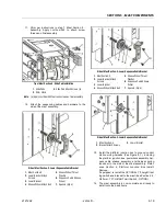
Mast Section-1 - Disassembly
Mast Section-1 - Disassembly
1.
1. Rem
Remove t
ove the fo
he four (4
ur (4) larg
) large scr
e screws (2 e
ews (2 each s
ach side
ide))
attaching the lift cylinder mounting block to mast
attaching the lift cylinder mounting block to mast
section-1. Slide the cylinder out of the mast section
section-1. Slide the cylinder out of the mast section
and move to a suitable work surface.
and move to a suitable work surface.
2.
2. At th
At the top
e top end o
end of mas
f mast sect
t section-1
ion-1, remo
, remove the
ve the pin
pin
attaching the chain anchor block to the mast and
attaching the chain anchor block to the mast and
remove chain/anchor block assemblies from the
remove chain/anchor block assemblies from the
mast and lay aside.
mast and lay aside.
3.
3. Remov
Remove sli
e slide pa
de pads an
ds and shi
d shims f
ms from m
rom mast se
ast section
ction-1,
-1,
if necessary.
if necessary.
Mast disassembly should now be complete.
Mast disassembly should now be complete.
5.
5.9
9 CY
CYLIN
LINDE
DER
R DI
DISA
SASS
SSEM
EMBL
BLY
Y
(See
(See Figure 5-3.
Figure 5-3. )
)
1.
1. Befor
Before dis
e disassemb
assembling
ling the c
the cylind
ylinder
er, clea
, clean away
n away all
all
dirt and foreign substances from openings, particu-
dirt and foreign substances from openings, particu-
larly the head area.
larly the head area.
NOTE:
NOTE:
Always protect the chrome surface of the cylinder
Always protect the chrome surface of the cylinder
rod during assembly and disassembly. Any damage
rod during assembly and disassembly. Any damage
to this surface will require replacement of the rod.
to this surface will require replacement of the rod.
2.
2. Exte
Extend th
nd the rod
e rod until
until the p
the piston
iston bott
bottoms o
oms out ag
ut against
ainst
the cylinder head.
the cylinder head.
3.
3. Comp
Compress t
ress the he
he head ret
ad retraini
raining ri
ng ring en
ng enough
ough to al
to allow
low
the cylinder head to be removed.
the cylinder head to be removed.
4.
4. Caref
Carefully s
ully slide
lide the he
the head/ro
ad/rod/pis
d/piston
ton assemb
assembly o
ly out of
ut of
the cylinder tube. A gentle tap on the head
the cylinder tube. A gentle tap on the head assembly
assembly
may be required to remove the head from the cylin-
may be required to remove the head from the cylin-
der tube.
der tube.
5.
5. Place
Place the
the head/r
head/rod/p
od/piston
iston assemb
assembly o
ly on a
n a surfa
surface
ce
that will not damage the chrome.
that will not damage the chrome.
6.
6. Remov
Remove the
e the pisto
piston loc
n locknut
knut and s
and separa
eparate th
te the pis
e piston
ton
from the rod.
from the rod.
7.
7. Slide
Slide the h
the head o
ead off th
ff the rod
e rod from
from the p
the piston
iston end.
end.
NOTE:
NOTE:
When removing the old seals use only blunt tools, be
When removing the old seals use only blunt tools, be
sure there are no shar
sure there are no sharp edges that may damage the
p edges that may damage the
seal grooves during removal. Scratching the groove
seal grooves during removal. Scratching the groove
may cause by-pass.
may cause by-pass.
8.
8. Rem
Remove
ove and
and dis
discar
card al
d all ol
l old se
d seals
als..
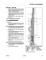
Figure 5-3.
Figure 5-3. Lift Cylinder
Lift Cylinder Component Cross-Section.
Component Cross-Section.
1.
1.
Cylinder
Cylinder Rod
Rod
6.
6.
Apply
Apply Anti-Seize
Anti-Seize
10.
10.
Piston
Piston
2.
2.
Cylinder
Cylinder Head
Head
7.
7.
Cylinde
Cylinder
r Tube
Tube
11.
11.
Wear
Wear Ring
Ring
3.
3.
Rod
Rod Wiper
Wiper
8.
8.
Spacer
Spacer
12.
12.
Piston
Piston O-Ring
O-Ring
4.
4.
Rod
Rod Seal
Seal
9.
9.
Piston
Piston Seal
Seal
13.
13.
Piston Lock
Piston Lock Nut (a)
Nut (a)
5.
5.
O-Ring
O-Ring
Note:
Note: (a) - T
(a) - Torque 100 - 120
orque 100 - 120 ft. lbs.
ft. lbs.
1
1
3
3
4
4
5
5
6
6
8
8
9
9
1
1
2
2
1
1
0
0
1
1
1
1
1
1
3
3
2
2
7
7


