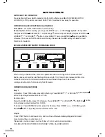
JK Exer FitLux 665 Скачать руководство пользователя страница 19

ENTER 

button on the keypad is to enter the figures that was input. 

ESC  button on the keypad is to cancel the figures that was input. 
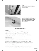
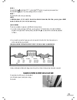
FAN: 

 It

s at the front top side of computer, controlled by the switch at the 


central bottom of computer. 

Two HOLDERS are on two sides of computer for placing water bottle or cell phone or others. 

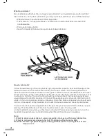
SAFETY KEY / EMERGENCY STOP KEY:

These two are designed in one big red and round key at the central bottom of computer.

Safety key is necessary for the operation. For safety use, you may remove or press down this key 

for emergency stop. Before beginning a workout session ensure that the safety key is securely 

attached to an article of clothing.

17

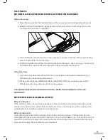
ERROR MESSAGE & TROUBLE SHOOTING

SMELL 

If any smell comes out from motor, please firstly spray out some silicone on the running board (Please 

refer to page : RUNNING BOARD MAINTENANCE), and see if the situation improves. 

Then consult the distributor for necessary help. 

E1 (ERROR 1): 

When the machine starts but computer could not read the signal from sensor for 7 seconds, E1 will be 
shown on the computer .

E6 (ERROR 6):

When the machine starts but computer could not read the VR signal from incline motor for 6 seconds, 
E6 will be shown on the computer

 .

If any above trouble happens, please consult the distributor

Содержание FitLux 665

Страница 1: ...665 MOTORIZED TREADMILL...

Страница 2: ...5 POSITIONED FOR OPERATION P 7 TREADMILL OPERATION P 7 ASSEMLY INSTRUCTIONS P 6 7 MASTER POWER SWITCH LOCATION P 15 COMPUTER INSTRUCTIONS P 16 17 HOW TO OPERATE P 8 15 ERROR MESSAGE TROUBLE SHOOTING...

Страница 3: ...you consult your physician Stop using this appliance if you feel dizziness or discomfort Medical approval and close supervision is necessary when appliance is used by or near handicapped individuals U...

Страница 4: ...ctronics Using electrical power other than that which has been specified will ultimately void any warranty implied or otherwise Never remove or bypass the electrical ground contained in the treadmill...

Страница 5: ...distributor for necessary maintenance 2 Please refer to below RUNNING DECK LUBRICATION to do necessary periodical maintenance for long term and functional operation PLEASE NOTE WITHOUT DOING PERIODICA...

Страница 6: ...about the spot that your feet would hit the belt as you are walking This should be about 18 inches from the motor cover You may walk on the treadmill to see where your feet land on the belt Please no...

Страница 7: ...5 1 2 3 4 5 A B C D E F G G H 1 MAIN FRAME 1 3 H TOOLS 1 COMPUTER 2 2 FRONT POST 3 2 HANDLEBAR 4 1 POWER CABLE 5 4 4 D BOLT WASHER 4 E BOLT 1 F BOLT 2 G CAP 4 4 C BOLT WASHER 4 4 B BOLT WASHER 2 2 2 A...

Страница 8: ...Then connect the cables from Main Frame and Front Post as D 1 Use Bolt F to fix cable to the hole as D 2 at the bottom end of Front Post as D 3 Ask one person to place Computer onto top of two Front...

Страница 9: ...een to operate BASIC INFORMATION 1 When safety key is removed There is no figure showing and you can read the instruction INSERT SAFETY KEY on the LCD 2 When safety key is positioned It is in MANUAL m...

Страница 10: ...e of screen will start flashing and next dot will be also flashing after running for 10m Total 40 dots represent 400m And incline dot matrix on the left side of screen will show number of laps from 0...

Страница 11: ...ots represent 400m And incline dot matrix on the left side of screen will show number of laps from 0 when start running and will jump to 1 after running for 400 meters And machine will stop automatica...

Страница 12: ...PH 6 0 KPH 8 0 KPH Interval 7 4 0 KPH 2 0 KPH 8 0 KPH 6 0 KPH Interval 8 5 0 KPH 4 0 KPH 8 0 KPH 4 0 KPH Interval 9 7 0 KPH 6 0 KPH 3 0 KPH 3 0 KPH Interval 10 8 0 KPH 2 0 KPH 6 0 KPH 3 0 KPH Interval...

Страница 13: ...erval 8 4 5 4 6 Interval 9 2 7 6 8 Interval 10 2 8 2 8 Interval 11 4 2 4 6 Interval 12 6 3 6 6 Interval 13 8 4 2 8 Interval 14 8 5 4 8 Interval 15 4 2 6 3 P 5 P 8 PROGRAM FOR INCLINE P 5 P 8 FOR INCLI...

Страница 14: ...0 KPH 2 2 0 KPH 4 10 0 KPH 6 Interval 12 5 0 KPH 6 5 0 KPH 3 8 0 KPH 6 6 0 KPH 6 Interval 13 3 0 KPH 8 5 0 KPH 4 2 0 KPH 2 2 0 KPH 8 Interval 14 3 0 KPH 8 6 0 KPH 5 2 0 KPH 4 6 0 KPH 8 Interval 15 5...

Страница 15: ...n to set desired time then Press ENTER again Step 4 Press START button to start exercising Second option Step 1 Press HRC button to choose H4 Step 2 You may press START button to begin operating follo...

Страница 16: ...nuous 20 seconds machine will be automatically stopped Then NO PULSE appears on the screen and machine resumes to ready to operate mode 7 If Actual Heartbeat is LOWER than Target Heartbeat incline wil...

Страница 17: ...ou like to set quick speed at 15kph you may press 1 5 button first on the QUICK SPEED keypad at the right side of overlay then press ENTER speed will be automatically adjusted to 15kph 2 If you want t...

Страница 18: ...GE Preset is 30 years old can be adjusted from 10 99 years old LEVEL L1 L3 HRC HI H4 USER U1 U3 PROGRAM P0 P12 LEVELS L1 L3 represent for 3 different intensities FUNCTION OF BUTTONS TIME It s to set w...

Страница 19: ...key for emergency stop Before beginning a workout session ensure that the safety key is securely attached to an article of clothing 17 ERROR MESSAGE TROUBLE SHOOTING SMELL If any smell comes out from...

Страница 20: ...inutes Repeat Steps 3 4 and 5 as needed ADJUSTING THE RUNNING BELT TENSION Adjust the belt tension if it begins to slip on the rollers This is important as it increased the longevity of the treadmills...

Страница 21: ...fficiently we suggest using your heart rate as a guide Everyone has what is called a Maximum Heart Rate Your maximum heart rate is the number of beats your heart makes per minute when you are running...

Страница 22: ...70 67 67 66 64 60 59 58 63 59 58 39 61 39 61 60 75 57 56 48 47 37 34 35 36 33 24 23 23 22 21 20 19 17 18 15 12 7 10 6 5 2 70 46 47 17 18 70 46 47 13 65 25 44 47 46 80 81 81 55 69 52 71 71 11 49 68 16...

Страница 23: ...10 CABLE Brown 170mm SPRING SPRING ADJUSTER T SLEEV BOLT M4 x 10 1 2 3 4 5 6 7 8 9 10 11 12 13 14 15 16 17 18 19 20 21 22 23 24 25 26 27 28 29 30 31 32 33 34 35 36 37 38 39 40 41 42 43 44 BOLT M8 x 45...

Страница 24: ...20160803...

Отзывы: