background image


User’s Manual


39 

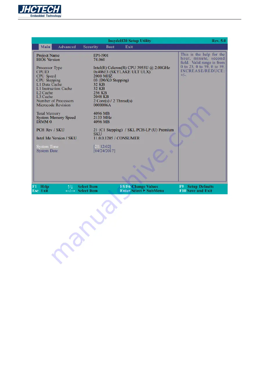
The Main menu is the first screen that you will see when you enter the BIOS Setup Utility. 


Figure 3.1 Main 

System Date 

The  date  format  is  <day>,  <month>,  <date>,  <year>.  Day  displays  a  day,  from  Sunday  to  Saturday. 

Month displays the month, from January to December. Date displays the date, from 1 to 31. Year displays 

the year, from 1980 to 2099.


System Time 

The time format is  <hour>, <minute>, <second>. The time is based on the 24-hour military-time clock. 

For example, 1 p.m. is 13:00:00. Hour displays hours from 00 to 23. Minute displays minutes from 00 to 

59. Second displays seconds from 00 to 59. 

3.9 Advanced 

The Advanced menu allows you to configure your system for basic operation. Some entries are defaults 

required by the system board, while others, if enabled, will improve the performance of your system or let 

Содержание ALAD-K1220T

Страница 1: ...User s Manual 1 ALAD K1220T User s Manual...

Страница 2: ...User s Manual 2 Version Note No Ver Note Date Writer 1 A1 0 First publish 20170504 Eileen Lee...

Страница 3: ...to be accurate and reliable However Shenzhen JHC Technology Co Ltd assumes no responsibility for its use nor for any infringements of the rights of third parties which may result from its use Acknowle...

Страница 4: ...nt materials service time and freight Please consult your dealer for more details If you think you have a defective product follow these steps 1 Collect all the information about the problem encounter...

Страница 5: ...e when the equipment is operated in a commercial environment This equipment generates uses and can radiate radio frequency energy and if not installed and used in accordance with the instruction manua...

Страница 6: ...Back light Power Select 13 2 3 6 JP8 M 2 Signal Select 13 2 4 I O indication 14 2 4 1 Ethernet Connector LAN 14 2 4 2 Power Input Connector DC IN 15 2 4 3 Power SW button Connector 15 2 4 4 USB Connec...

Страница 7: ...C 3 7 Getting Help 38 Insyde BIOS Setup Utility 38 System Date 39 System Time 39 3 9 1 ACPI Settings 40 3 9 2 CPU Configuration 41 Driver Installation 58 4 2 Installation 59 SYSTEM RESOURCE 63 5 1 WD...

Страница 8: ...User s Manual 1 General Information CHAPTER 1...

Страница 9: ...torage DC 9 36V power input 1 2 Features 1 Aluminum die casting chassis fanless design 2 12 1 LED TFT LCD 5 wire resistive or projected capacitive touch 3 Intel Celeron or Skylake U Core I3 I5 I7 CPU...

Страница 10: ...Optional 1 M 2 2242 B Key PCIe USB SATA Storage 1 2 5 SATA HDD or SSD SATA3 0 6Gbps 1 M 2 SATA or PCIe signal 1 3 2 Display and Touch Chipset Intel HD Graphics 520 Display Memory Shared system memory...

Страница 11: ...d 10 100 1000 Mbps integrated Interface 2 RJ45 1 3 4 Audio Optional Chip RealtekALC888S VD2 GR audio codec integrated Speaker 2 3W speaker out 1 3 5 Power Consumption Input Voltage DC 9 36V Power Cons...

Страница 12: ...on With SSD mSATA 1Grms IEC 60068 2 64 random 5 500 Hz 1 hr axis Shock during operation With SSD mSATA 10G IEC 60068 2 64 half sine 11 ms duration EMC CE FCC Class A 1 5 Mechanical Specifications ALAD...

Страница 13: ...User s Manual 6 Hardware Installation CHAPTER 2...

Страница 14: ...that is housed in an aluminum plate chassis Your HDD and SDRAM are all readily accessible by removing the aluminum cover Any maintenance or hardware upgrades can be easily completed after opening the...

Страница 15: ...he pins to connect them To close a jumper you connect the pins with the clip To open a jumper you remove the clip Sometimes a jumper will have three pins labeled 1 2 and 3 In this case you would conne...

Страница 16: ...s of the various jumpers The table below shows the function of each of the board s jumpers Figure 2 5 EPI I901 Jumper Jumpers Jumper Name Description JP1 COM3 RS232 Power Select 6 Pin Block JP2 COM4 R...

Страница 17: ...or RS232 with power The pin functions of Com 3 and COM 4 will vary according to JP1 s and JP2 s setting respectively 2 3 2 JP3 Power on Select JP3 is used to select the method of powering on the syst...

Страница 18: ...re 2 6 When using JP3 Power On feature to power the system back on after a power failure occurs the system may not power on if the power lost is resumed within 5 seconds power flicker 2 3 3 JP4 Clear...

Страница 19: ...he ROM BIOS To load the default values stored in the ROM BIOS please follow the steps below 1 Power off the system and unplug the power cord 2 Set JP4 pins 2 and 3 to On Wait for a few seconds and set...

Страница 20: ...wer supplied with the LCD panel Important Before powering on the system make sure that the power settings of JP7 match the LCD panel s specification Selecting the incorrect voltage will seriously dama...

Страница 21: ...W 3 HDMI 4 USB 4 5 LAN 2 6 COM 2 2 4 1 Ethernet Connector LAN The ALAD K1220T is equipped with two Intel I210AT chip for 10 100 1000Mbps Ethernet controllers The Ethernet port provides a standard RJ 4...

Страница 22: ...81mm connector provides maximum of 60W power and is considered a low power solution Connect a DC power cord to this connector Use a power adapter within 9 36V DC output voltage Using a voltage out of...

Страница 23: ...5 The 9 pin connector allows you to connect 2 additional USB 2 0 ports USB 4 5 The additional USB ports may be mounted on a card edge bracket Install the card edge bracket to an available slot at the...

Страница 24: ...gure as RS232 RS422 and RS485 by BIOS setting The serial ports are asynchronous communication ports with 16C550A compatible UARTs that can be used with modems serial printers remote display terminals...

Страница 25: ...e 2 6 COM3 4 Serial Port Pin Assignments Pin Signal Name Pin Signal Name 1 DCD 6 DSR 2 RxD 7 RTS 3 TxD 8 CTS 4 DTR 9 RI 5V 12V 5 GND 10 NC 2 4 7 SATA0 Serial ATA Connector There are Serial ATA 3 0 por...

Страница 26: ...A Power Connector Table 2 8 SATA Power Pin Assignments Pin Signal Name 1 DC 12V 2 GND 3 GND 4 DC 5V 2 4 9 Digital IO Connector The 8 bit Digital I O 2 5 Pin connector provides powering on function to...

Страница 27: ...User s Manual 20 2 5 Installation 2 5 1 HDD SSD Installation Step 1 Unscrew the 2 screws on the HDD cover and open the HDD cover Figure 2 24...

Страница 28: ...User s Manual 21 Figure 2 25 Step 2 Screw the HDD SSD on the drive bay though 4 screws Figure 2 26 Step 3 Push the drive bay into the SATA connector and screw 1 screw to lock drive bay...

Страница 29: ...User s Manual 22 Figure 2 27 Figure 2 28 Step 4 Push HDD cover back to the chassis screw 2 screws on the HDD cover...

Страница 30: ...User s Manual 23 Figure 2 29 2 5 2 Installing SODIMM module Step 1 Unscrew the 9 screws on the back chassis and open the back chassis...

Страница 31: ...4 Figure 2 30 Figure 2 31 Step 2 Pull out 4 cable connectors from front IO card touch panel and LCD Figure 2 32 Step 3 Hold the module with its notch aligned with the socket of the board and insert it...

Страница 32: ...nual 25 angle into the socket Push down the module until the clips at each end of the socket lock into position Figure 2 33 Figure 2 34 Step 4 Connect 4 cable connectors into front IO card touch panel...

Страница 33: ...User s Manual 26 Figure 2 35 Step 5 Close the chassis back to the front panel and screw the 9 screws on the chassis Figure 2 36...

Страница 34: ...User s Manual 27 2 5 3 Installing mSATA Flash Card module Step 1 Unscrew the 9 screws on the back chassis and open the back chassis Figure 2 37 Figure 2 38...

Страница 35: ...from front IO card touch panel and LCD Figure 2 39 Step 3 Hold the module with its notch aligned with the socket of the board and insert it at a 30 degree angle into the socket screw 1 screws to the h...

Страница 36: ...User s Manual 29 Figure 2 41 Step 4 Connect 4 cable connectors into front IO card touch panel and LCD Figure 2 42 Step 5 Close the chassis back to the front panel and screw the 9 screws on the chassis...

Страница 37: ...User s Manual 30 Figure 2 43 2 5 4 Installing I O Cover Step 1 Put the panel PC on the plane desk as shown in the following picture Figure 2 44...

Страница 38: ...User s Manual 31 Step 2 Aligning the I O cover at the I O opening note the key holes Figure 2 45 Figure 2 46...

Страница 39: ...User s Manual 32 Step 3 Plug and push the I O cover into the I O opening Figure 2 47 2 5 5 Front USB Step 1 Pull out the rubber cover from the hole Figure 2 48...

Страница 40: ...User s Manual 33 Figure 2 49 Step 2 Plug USB device into the USB type A connector Figure 2 50...

Страница 41: ...User s Manual 34 2 5 6 Panel Mounting Step 1 Install the panel PC into the panel opening Figure 2 51 Step 2 Pull out the 4 clamps from the holes around the two sides of the bezel Figure 2 52...

Страница 42: ...User s Manual 35 Figure 2 53 Step 3 Insert the screws into each clamp and fasten them Figure 2 54 Figure 2 55...

Страница 43: ...User s Manual 36 BIOS Setup CHAPTER 3...

Страница 44: ...e configuration settings are either predefined according to the Load Optimal Defaults settings which are stored in the BIOS or are automatically detected and configured without requiring any actions T...

Страница 45: ...ditional options are available for that field To display the submenu move the highlight to that field and press Enter 3 7 Getting Help Main Menu The on line description of the highlighted setup functi...

Страница 46: ...Year displays the year from 1980 to 2099 System Time The time format is hour minute second The time is based on the 24 hour military time clock For example 1 p m is 13 00 00 Hour displays hours from...

Страница 47: ...eatures according to your preference Important Setting incorrect field values may cause the system to malfunction Figure 3 2 Advanced 3 9 1 ACPI Settings This section is used to configure the system A...

Страница 48: ...er a power failure G3 state Always On The system working state Always Off Off except for trickle current to devices such as the power button 3 9 2 CPU Configuration This section is used to configure t...

Страница 49: ...ion configures the video settings Figure 3 5 Video Configuration Primary Display Select which of IGD Graphics device should be Primary Display Integrated Graphics Device Enable or disable the IGD func...

Страница 50: ...l 43 Figure 3 6 Boot display LCD Panel Type Select the LCD panel type LCD Panel Color Depth Select the LCD panel color depth 18 bit 24 bit 36 bit and 48 bit Dimming Control Select Dimming Type PWM DC...

Страница 51: ...s Manual 44 Figure 3 7 LCD panel 3 9 4 Audio Configuration This section is used to configure the audio settings Figure 3 8 Audio Configuration Audio Controller Control the detection of the Azalia dev...

Страница 52: ...SATA controller and the type of hard disk drive which are installed in your system unit Figure 3 9 SATA Configuration SATA Controller This field is used to enable or disable Serial ATA devices HDC Co...

Страница 53: ...l ATA Port 0 and 1 This field is used to enable or disable the serial ATA port 3 9 6 USB Configuration This section is used to configure the parameters of the USB device Figure 3 10 USB Configuration...

Страница 54: ...and PCI Express Port 4 link to the EIO connector PCI Express Root Port 5 links to the Ethernet controller I210AT on LAN1 PCI Express Root Port 6 links to the Ethernet controller I210AT on LAN2 PCI Ex...

Страница 55: ...User s Manual 48 Figure 3 12 PCI Express Root Port Figure 3 13 PCI Express Root Port PCI Express Root Port This field is used to enable or disable the PCI Express Root Port PCIe Speed...

Страница 56: ...r Gen3 3 9 8 ME Configuration This section configures settings relevant to flash ME region Me Fw Image Re Flash This field is used to enable or disable the flash ME region Please set this item as Enab...

Страница 57: ...1 to Boundary 4 Set the boundary temperatures that determine the operation of the fan with different fan speeds accordingly For example when the CPU temperature reaches boundary 1temperature the syst...

Страница 58: ...ttings to use the serial port Disable No configuration Enable User configuration Type Choose RS232 RS422 RS485 Peer to Peer for the serial port type COM 5 for Resistance touch panel controller COM 6 f...

Страница 59: ...le the case open AC Power Loss Set the AC power loss always off on This item is only working when JP6 auto power on jumper is set as 1 2 on PC Health Status This field only displays the PC health stat...

Страница 60: ...eration No changes to the current state Disable Disable and deactivate TPM Enable Enable and activate TPM Clear TPM Remove all TPM ownership contents Set Supervisor Password Set the supervisor s passw...

Страница 61: ...Boot Type Network Stack This option is shown only when the boot type is set to Dual or UEFI Enable or disable UEFI network stack It supports the operation of these functions or software Windows 8 BitL...

Страница 62: ...r all bootable devices Use and keys to arrange the priority of the listed boot devices Advance For this option determine the boot order for the devices within each category Use and keys to arrange the...

Страница 63: ...User s Manual 56 Figure 3 21 Boot Type Order Figure 3 22 USB Boot...

Страница 64: ...this field and then press Enter to exit the system setup and save your changes Load Optimal Defaults Select this field and then press Enter to load optimal defaults Discard Changes Select this field a...

Страница 65: ...User s Manual 58 Driver Installation CHAPTER 4...

Страница 66: ...Intel USB 3 0 Drivers For Windows 7 and Windows 8 1 Step 9 Install IO Driver Please read instructions below for further detailed installations 4 2 Installation Insert the ALAD K1220T CD ROM into the...

Страница 67: ...ver 1 Setup is ready to install the driver Click Next 2 Click I accept the terms in the license agreement then click Next 3 Select the program features you want installed then click Next 4 Click Insta...

Страница 68: ...is ready to begin installation Click Install 5 Please wait while the program features are being installed 6 After completing installation click Finish Step 8 Install Intel USB 3 0 Drivers For Windows...

Страница 69: ...anual 62 2 Read the license agreement carefully Click I accept the terms in the License Agreement then click Next 3 Read the file information then click Next 4 Setup is ready to install the driver Cli...

Страница 70: ...User s Manual 63 SYSTEM RESOURCE CHAPTER 5...

Страница 71: ...User s Manual 64 5 1 WDT Function WDT Set Example See the function WD_SetTimerValue ucResetTime...

Отзывы: