


Jetter AG
Electrical connection | 6
JVM-104-O09 User Manual
22 / 62
6.1 Pin assignment of Deutsch connector
Features
The Deutsch connector has the following functions:
■
Power supply to the JVM-104-O09
■
Power supply for higher load currents
■
Multi-purpose inputs
■
Multi-purpose outputs
■
CANopen® bus interface: CAN 1
■
Recognition of the ignition signal
NOTICE
Design for higher currents
Pin 7 of the DEUTSCH connector has been rated to support higher currents.
►
Therefore, dimension the size of the wire for pin 7 accordingly.
INFO
Ignition
To launch the JVM-104-O09, pin 8 (I) must be connected with pin 6. The
ignition control signal (I) is connected with the key position
Ignition ON
.
INFO
Current consumption
When the JVM-104-O09 is energized, the current consumption is temporarily
higher. To ensure a reliable start-up of the device, provide at least 3 times the
typical current required.
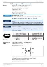
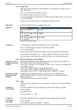
1
6
7
12
Fig. 10:
Deutsch connec-
tor, 12 pins
12
Multi-purpose input MFQE2
1
Reference potential (GND)
11
Multi-purpose input MFQE1
2
Multi-purpose output PA1
10
CAN_1_H
3
Multi-purpose output PA2
9
CAN_1_L
4
Multi-purpose output PA3
8
Ignition (+)
5
Multi-purpose output PA4
7
VBAT_PA
6
VBAT_ECU
Pinout of the H-
bridge
The H-bridge is connected to the following outputs:
■
Multi-purpose output PA3
■
Multi-purpose output PA4
PA3H
PA3L
PA4H
PA4L
PA3
PA4
Fig. 11:
H-bridges
For programming, switch the H-bridge to the desired direction:
■
Anti-clockwise rotation: PA3H and PA4L
■
Clockwise rotation: PA4H and PA3L


