


3.8.1
Motor connection diagram
Motor cable
All motor cables must be shielded. To connect servo motors, use ready-
made motor cables from Jetter AG. The available cables are listed in the
appendix in Tabelle A.8. Equivalent shielded cables must be used for the
connection of third-party motors.
Motor connection
W
V
U
ϑ
-
ϑ
+
ϑ
n.c
n.c
BRK_OUT
BRK_GND
Motor
3
~
X12/13/14
1
2
3
4
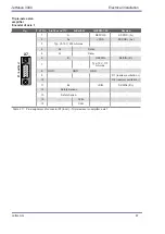
Fig. A:
Recommended
connection of the motor
holding brake up to a
maximum motor brake
current of 2 A.
Brake (+)
Brake (-)
+24 V DC
for motor
holding brake
24 V DC
+
W
V
U
ϑ
-
ϑ
+
ϑ
n.c
n.c
BRK_OUT
BRK_GND
Motor
3
~
X12/13/14
1
2
3
4
Fig. B:
Recommended
connection of the motor
holding brake with a
motor brake current of
2 A or higher.
This type of connec-
tion has no broken wire
detection!
The temperature sensor connection is shown in the configuration by "Standard encoder interface".
Fig. 3.12 Connection of a servo motor with motor holding brake
W
V
U
ϑ
n.c
n.c
BRK_OUT
BRK_GND
Motor
3
~
X12/13/14
2
1
4
3
H
DSL-
DSL+
Hiperface DSL-
Hiperface DSL+
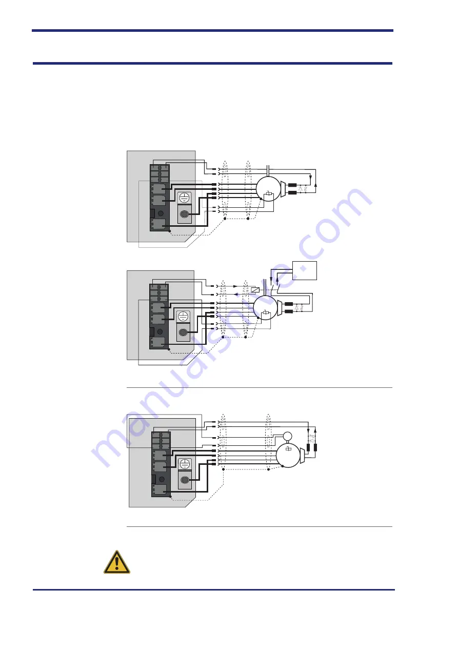
Recommended
connection of the motor
holding brake up to a
maximum motor brake
current of 2 A.
In the "HIPERFACE
DSL" (see order
number code on page
the two-wire connec-
tion of the encoder is
connected to terminals
X12/13/14 - 1 and 2.
Fig. 3.13 Connection of a servo motor with HIPERFACE DSL encoder system
CAUtIoN
For terminals X12/13/14 - 1 and 2, ensure that the temperature sensor
used has basic insulation against the motor winding in accordance with EN
61800-5-1.
Jetter AG
61
JetMove 3000
Electrical installation
Содержание JetMove 3000
Страница 1: ...We automate your success User Manual JetMove 3000 Servo Amplifier 608880297...
Страница 30: ...JM 3000 Example supply unit with two servo amplifiers BG1 Fig 2 11 JM 3000 Mechanical installation 30 Jetter AG...
Страница 32: ...Mechanical installation 32 Jetter AG...
Страница 70: ...70 Jetter AG...
Страница 74: ...Diagnostic functions 74 Jetter AG...
Страница 76: ...Standard version S1 76 Jetter AG...