background image


1


OWNER’S MANUAL 

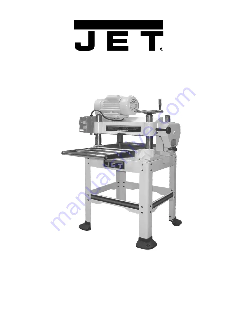
JWP-16OS Woodworking Planer 


WMH Tool Group 

Consumer Woodworking Division 
2420 Vantage Drive 
Elgin, IL 60123 
Ph: 888-594-5866 

 Fax: 800-626-9676 

M-708531 Rev A 10/03 

www.wmhtoolgroup.com 

Copyright © WMH Tool Group 

Содержание JWP-16OS

Страница 1: ...ANUAL JWP 16OS Woodworking Planer WMH Tool Group Consumer Woodworking Division 2420 Vantage Drive Elgin IL 60123 Ph 888 594 5866 Fax 800 626 9676 M 708531 Rev A 10 03 www wmhtoolgroup com Copyright WMH Tool Group ...

Страница 2: ... or accidents normal wear and tear repair or alterations outside our facilities or to a lack of maintenance WMH TOOL GROUP LIMITS ALL IMPLIED WARRANTIES TO THE PERIOD SPECIFIED ABOVE FROM THE DATE THE PRODUCT WAS PURCHASED AT RETAIL EXCEPT AS STATED HEREIN ANY IMPLIED WARRANTIES OR MERCHANTIBILITY AND FITNESS ARE EXCLUDED SOME STATES DO NOT ALLOW LIMITATIONS ON HOW LONG THE IMPLIED WARRANTY LASTS ...

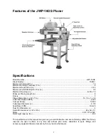
Страница 3: ...ment 16 Checking Work Table Parallel to Cutterhead 16 Adjusting Work Table Parallel to Cutterhead Fine Adjustment 17 Adjusting Work Table Parallel to Cutterhead Major Adjustment 17 Transmitting Rollers 18 Infeed Outfeed Roller Spring Tension Adjustment 18 Anti Kickback 18 Checking and Adjusting the Feed Roller Height 19 Gearbox 20 Operation 20 Table Locks 20 Power Feed 21 Handwheel 21 Depth Limite...

Страница 4: ...4 Stand Assembly 34 Stand Assembly Parts List 34 Electrical Schematic for JWP 16OS Planer 35 ...

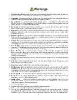
Страница 5: ...nger of slipping 9 Power off Make sure the machine is either unplugged or electrically disconnected and locked out when performing maintenance or service work Also make sure switch is in OFF position before plugging in power cord Never leave the machine running unattended Do not leave machine until it comes to a complete stop 10 Cutterhead Keep knives sharp and free of all rust and pitch Make sure...

Страница 6: ...talled 3 Remove or fasten loose articles ofclothing such as neckties etc Containlong hair 4 Remove jewelry such as finger rings watches bracelets etc 5 Use approved safety glasses and or face shield toprotecteyes and use other personal safety equipment as required Do not wear gloves 6 Disconnect machine from power source before makingany adjustments or cleaning chips away from machine 7 Keep the f...

Страница 7: ...x W x T in 16 1 8 x 1 x 1 8 Cutterhead Speed RPM 4 500 Cuts per Minute 13 500 Cutterhead Diameter in 2 7 8 Feed Rate FPM 16 20 Dust Port Diameter in 4 Overall Dimensions L x W x H in 48 x 32 x 51 Motor 3HP 1Ph 230V Net Weight approx lbs 430 The specifications in this manual are given as general information and are not binding WMH Tool Group reserves the right to effect at any time and without prio...

Страница 8: ...ly 1 Planer Unit 1 4 Dust Hood 2 In Outfeed Extension Roller Assembly 1 Handwheel Cast Foot Assembly 4 Cast Feet 1 Hardware Bag consisting of 8 Socket Head Flat Screws 8 Flat Washers 8 Hex Nuts Stand Assembly 4 Stand Legs 2 Stand Braces long 2 Stand Braces short 2 Stand Top front rear 1 Stand Top left 1 Stand Top right 1 Hardware Bag consisting of 32 Carriage Bolts 32 Flat Washers 32 Hex Nuts Acce...

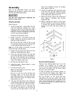
Страница 9: ...les of the front and rear assemblies previously constructed the JET logo is the front using 4 ea carriage bolts flat washers and nuts 8 Take one short stand brace 12 and secure to the left legs of the front and rear assembly with 4 ea carriage bolts washers and nuts 9 Take the right stand top 13 this piece has the cutout and secure it to the front and rear legs top mounting holes on the right side...

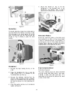
Страница 10: ...ss it on the handwheel D Fig 4 4 Place flat washer and hex nut on shaft and tighten with wrench 5 Mount the handle C Fig 4 for the handwheel in the threaded hole in the handwheel and tighten with a wrench placed over the flat 12mm on the handle Figure 4 Extension Rollers Mount two extension rollers to the table using the provided 6 ea M8 x 20 hex cap screws 12mm 6 ea M8 flat washers and 6 ea M8 x ...

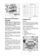
Страница 11: ...machine but if one is necessary make sure the cord rating is suitable for the amperage listed on the machine s motor plate An undersized cord will cause a drop in line voltage resulting in loss of power and overheating The chart in Figure 7 shows the correct size cord to use based on cord length and motor plate amp rating If in doubt use the next heavier gauge The smaller the gauge numbers the hea...

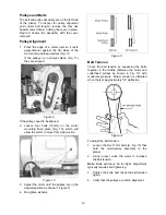
Страница 12: ...ll allow the motor to move from side to side Figure 10 3 Adjust the motor until the pulleys are in the aligned position as shown in Figure 11 4 Re tighten all bolts Figure 11 Belt Tension Check the belt tension by squeezing the belts together in the middle between the motor and cutterhead pulleys as shown in Fig 12 with moderate pressure Proper tension is indicated when there is approximately 1 4 ...

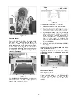
Страница 13: ...m power source 2 Select a side left or right and lay a steel ruler or straightedge across both rollers A 3 On the side selected loosen the screws B with an Allen wrench and turn the eccentric shafts C 12mm hex head adjustment to raise or lower the rollers to the desired level Use a feeler gauge to measure the clearance between the table and the bottom of the straightedge 4 When the proper height i...

Страница 14: ...150mm The distance of upward or downward movement is controlled by the handwheel B One revolution of the handwheel is 0 158 4mm Before moving the head assembly up or down loosen the lock knobs C After obtaining the proper height for the head assembly tighten the lock knobs Note The JWP 16OS Planer has two lock knobs one is located by the handwheel C Fig 19 The other is located on the opposite left...

Страница 15: ...nife A continue to loosen the gib screws D until the springs E begin raising the knife When knife comes into contact with the center protrusion B of the gauge adjust the jack screws higher or lower to touch the bottom of the knife then snug up the gib by lightly backing out the six gib screws D against the slot Note At this time only tighten the knife in the slot just enough to hold knife in posit...

Страница 16: ...rting with the end screws first and then the center screws until the knife is securely held in the cutterhead Tighten the remaining two knives in the same manner Important After replacing and checking knives CHECK AGAIN carefully Make certain the direction of knives is correct and all eighteen 3 knives x 6 screws locking screws are tightened securely Table Adjustment To perform the table adjustmen...

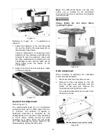
Страница 17: ... in position and retighten the cap screws 4 Recheck the table to cutterhead parallelism again as described in the previous section then repeat steps 1 3 until the deviation is less than 0 004 Figure 26 Adjusting Work Table Parallel to Cutterhead Major Adjustment Refer to Figure 27 1 Disconnect the machine from power source 2 On the underside of the base remove bolt A and loosen bolt B which will a...

Страница 18: ...e equal at both ends of each roller To adjust the spring tension of the infeed and outfeed rollers turn screws A Fig 29 with a hex wrench A clockwise turn increases tension on the pressure spring Fig 30 a counterclockwise turn decreases tension Adjust the screws at the other end of the rollers with the same number of turns Note The most effective pressure settings are dependent on the type of lumb...

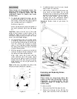
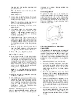
Страница 19: ...ly high enough to place the gauge block J Fig 32 on the table directly underneath the cutterhead D Fig 32 Using a 0 02 0 5mm feeler gauge K Fig 32 placed on top of the gauge block lower the head assembly until the knife just touches the feeler gauge when the knife is at its lowest point Do not move the working table any further until the infeed and outfeed rollers are adjusted Figure 32 3 Move the...

Страница 20: ...tuations wood types and other variables that differ from shop to shop must be considered in order to operate this planer safely Always consider safety and common sense first when operating this or other machinery 1 Always inspect lumber for defects warping cupping twisting etc Do not use lumber of questionable quality 2 Check lumber for nails staples imbedded gravel etc before planing 3 Use the fu...

Страница 21: ...bly by 0 158 4mm Make sure the height scale is properly adjusted With the depth limiting clip installed you cannot cut full width more than 1 8 in a single pass 3 16 if lumber can fit on either side of the depth limiting clip While cutting this much material is possible it is not recommended Depth Limiter The Model JWP 16OS Planer is equipped with a depth limiter located on the bottom of the cutte...

Страница 22: ...of protection as well as reducing friction between lumber and the table making cuts faster and smoother Avoid any wax that contains silicone or other synthetic ingredients These materials can find their way into lumber and can make staining and finishing difficult Another option is talcum powder applied with a blackboard eraser rubbed in vigorously once a week this will fill casting pores and form...

Страница 23: ...Fig 39 and filler cap A Fig 40 Drain dirty oil thoroughly 2 Tighten the drain plug 3 Fig 39 3 Fill with clean lubricant through hole A Fig 40 Tighten filler cap A Fig 40 Figure 40 No Fig Position Interval Suitable Types of Lubricant 1 39 Drive Chain Inspect and lubricate monthly Grease 2 39 Gear Box When operated more than 2 500 hours HD 100 Mobil Gear 627 Shell Omala 100 ESSO Spartan EP 100 3 41 ...

Страница 24: ...24 Figure 41 Figure 42 Figure 43 Optional Accessories 708814 Knives set of 3 708119 Universal Mobil Base ...

Страница 25: ...n Grain Dull knives Sharpen knives Dull knives Sharpen knives Too heavy a cut Adjust proper depth Rough Raised Grain Moisture content too high Remove high moisture content from wood by drying Dull knives Sharpen or replace knives Feed speed too slow Increase speed Rounded glossy surface Cutting depth too shallow Increase depth Inadequate feed roller pressure Adjust feed roller tension If proper te...

Страница 26: ... any signs of electrical arcing which is a sure indicator of loose connections or circuit overload Motor starter failure Examine motor starter for burned or failed components If damage is found replace motor starter If motor starter looks okay but is still suspect you have two options have a qualified electrician test the motor starter for function or purchase a new starter and establish if that w...

Страница 27: ...27 Parts List for the JWP 16OS Planer Head Assembly ...

Страница 28: ...d Cap Screw M6 12L 3 26 JWP16OS 126 Collector Hood 1 27 JWP16OS 127 Upper Cover 1 28 JWP15H 040 Deflector Plate 1 29 JWP16OS 129 Cap 3 30 TS 1504101 Socket Head Cap Screw M8 50L 4 31 TS 1540072 Hex Nut M10 1 25M 4 33 JWP16OS 133 Label Direction 1 34 JWP16OS 134 Handwheel 1 35 JWP15H 060 Handle 1 36 JWP15H 109 Knob 1 37 JWP15H 108 Lock Bushing 2 38 TS 1482021 Hex Cap Screw M6 12L 4 39 TS 1550041 Fl...

Страница 29: ...y 5 5 22 2 69 JWP16OS 169 Rivet 2 70 JWP15H 031 Sprocket 4 72 TS 1482031 Hex Cap Screw M6 16L 2 73 JWP15H 073 Chain 06B 63P 1 74 JWP16OS 174 Chip Bracket 1 75 JWP16OS 175 Shaft 1 76 JWP16OS 176 Knob 1 77 JWP15H 045 Retaining Ring ETW 15 2 78 JWP15H 042 Collar 45 79 JWP15H 041 Anti Kick Finger 44 80 JWP16OS 180 Shaft 1 81 JWP16OS 181 Infeed Roller 1 82 JWP15H 027 Sprocket 1 83 JWP16OS 183 Power Cor...

Страница 30: ... Column 4 5 TS 1523041 Socket Set Screw M6 12L 4 6 JWP15H 203 Column 4 7 JWP16OS 207 Base 1 8 TS 1525021 Socket Set Screw M10 12L 8 9 JWP16OS 209 Roller 2 10 BB 608Z Ball Bearing 4 11 JWP15H 104 Eccentric Shaft 4 12 JWP15H 221 Bracket 1 13 JWP15H 222 Shaft 1 14 JWP15H 223 Sprocket 1 15 JWP15H 224 Retaining Ring STW 15 1 16 JWP16OS 216 Chain 41 148P 1 17 TS 1550061 Flat Washer M8 18 ...

Страница 31: ... 25 JWP15H 208 Bushing 1 26 JWP16OS 226 Key 4 4 20 1 27 JWP16OS 227 Leadscrew 1 28 JWP16OS 228 Scale 1 29 TS 1531012 Machine Screw Pan Head Phillips M3 6L 2 30 JWP16OS 230 Column 1 31 TS 1490031 Hex Cap Screw M8 20L 6 32 TS 1524031 Socket Set Screw M8 12L 6 33 TS 1490051 Hex Cap Screw M8 30L 4 35 JWP16OS 235 E ring ETW 10 4 36 JWP15H 111 Roller Frame 2 37 TS 1482021 Hex Cap Screw M6 12L 12 38 TS 1...

Страница 32: ...32 Gear Box Assembly ...

Страница 33: ...Pin 2 12 JWP15H 339 Oil Plug 2 13 OS 28408 Oil Seal TC28x40x8 1 14 JWP15H 301 Gear Box 1 15 JWP15H 336 Gasket 1 16 BB 6201Z Ball Bearing 6201Z 3 17 JWP15H 314 Shaft 1 18 JWP15H 320 Key 6x6x40 1 19 JWP15H 312 Gear 71T 1 20 JWP15H 334 Knob 1 21 JWP15H 325 Sprocket 12T 1 22 TS 1482031 Hex Cap Screw M6x16L 1 23 JWP15H 318 Gear Assembly 96 92T 1 24 JWP15H 323 Shaft 1 25 JWP15H 322 Spring 1 26 JWP15H 32...

Страница 34: ...er Front Brace 2 3 JWP16OS 403 Down Side Brace R 2 4 JWP16OS 404 Down Front Brace 2 5 TS 1550061 Flat Washer M8 48 6 TS 0561021 Hex Nut 5 16 18 32 7 JWP16OS 407 Carriage Bolt 5 16 18 14L 32 8 TS 1540061 Hex Nut M8 12 9 TS 1515021 Socket Head Flat Screw M8x20L 8 10 JWP16OS 410 Foot 4 12 JWP16OS 412 Leg 4 13 JWP16OS 413 Upper Side Brace R 1 ...

Страница 35: ...35 Electrical Schematic for JWP 16OS Planer ...

Страница 36: ...36 WMH TOOL GROUP 2420 Vantage Drive Elgin IL 60123 Ph 888 8097 7129 Fax 800 274 6840 www wmhtoolgroup com ...

Отзывы: