background image


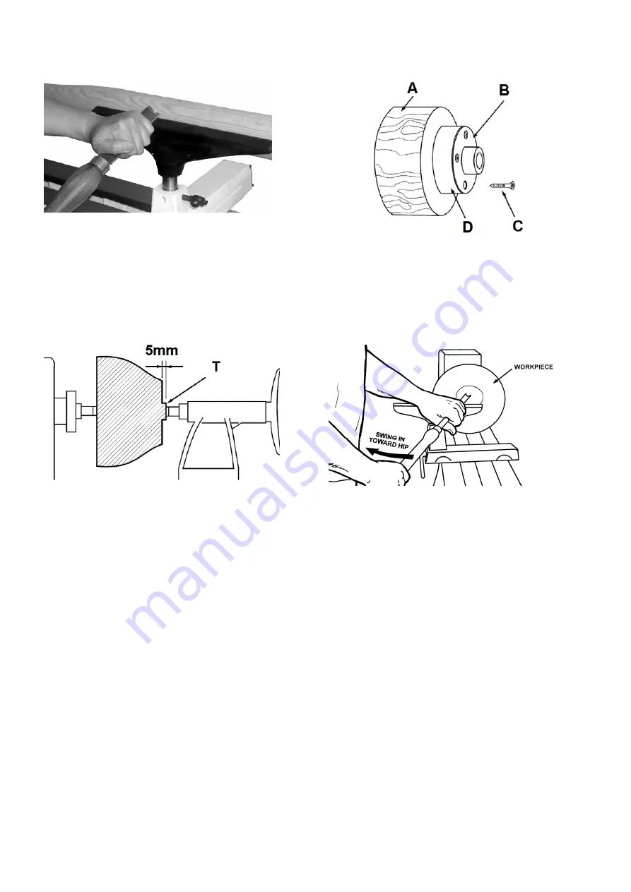
Fig 15 


6.5  Bowl turning 

Turn outside of bowl between centres. 

Turn a short tenon the size of the hole in the faceplate 
 (T, Fig 16). This will allow centring the workpiece. 


Fig 16 

Mount the workpiece (A, Fig 17) directly to the face plate 
using 4 wood screws (C) from the back. Be careful to use 
screws short enough not to interfere with the cutting process 
but long enough to hold the workpiece securely to the face 
plate. 

If screw mounting is not allowed at all, the work may be glued 
to a backing block (D) and the backing block screwed to the 
face plate. A piece of paper in the glue joint will prevent 
damaging the wood when separated later. 

Mount the face plate with the workpiece already attached onto 
the spindle nose thread and hand tighten. 

Move tailstock away, remove centre from tailstock to prevent 
injury. 

Turn the workpiece by hand to see if it rests securely and can 
be rotated freely. 


Fig 17 

For face plate turning the tool rest is set slightly lower than 
centre line. 

Caution:  

Cut with your chisel on the left side of the turning centre only. 

Use left hand to control cutting edge of gouge, while right 
hand swings tool handle around toward your body (Fig 18). 


Fig 18 

Try to make one, very light continuous movement from the rim 
to the bottom of the bowl to ensure a clean, sweeping curve 
through the workpiece. 

Move tool support to the exterior to re-define bottom of bowl. 


6.6  Sanding and Finishing 

Remove the tool rest and begin with a fine grit sandpaper (120 
grit) and progress through each grit, using only light pressure. 

Use power sanding techniques to avoid concentric sanding 
marks. 

Finish sanding with 220 grit. 

Apply first coat of finish. Allow to dry before sanding again 
with 320 or 400 grit sandpaper. 

Turn lathe back on and make a separation cut through the 
base. Stop at about dia. 80mm and use a fine tooth saw to 
separate the bowl from the waste. 

Apply additional finish coats and allow to dry before buffing. 


Содержание JWL-1221-M

Страница 1: ...JWL 1221 M WOOD LATHE Original GB Operating Instructions Translations D Gebrauchsanleitung F Mode d emploi TOOL FRANCE SARL 9 Rue des Pyrénéés 91090 Lisses France www jettools com M JWL 1221 M 2019 01 ...

Страница 2: ...enrichtlinie Directive Machines 2014 30 EU electromagnetic compatibility elektromagnetische Verträglichkeit compatibilité électromagnétique designed in consideration of the standards und entsprechend folgender zusätzlicher Normen entwickelt wurde et été développé dans le respect des normes complémentaires suivantes EN ISO 12100 2010 EN 60204 1 2006 A1 2009 EN 61000 3 2 2014 EN 61000 3 3 2013 EN 55...

Страница 3: ...free from material defects and manufacturing faults This warranty does not cover any defects which are caused either directly or indirectly by incorrect use carelessness damage due to accidents repairs or inadequate maintenance or cleaning as well as normal wear and tear Further details on warranty e g warranty period can be found in the General Terms and Conditions GTC that are an integral part o...

Страница 4: ...alcohol or any medication Be aware that medication can change your behaviour Keep an ergonomic body position Maintain a balanced stance at all times Never reach into the machine while it is operating or running down Keep children and visitors a safe distance from the work area Never leave a running machine unattended Before you leave the workplace switch off the machine Do not operate the electric...

Страница 5: ...explode when being processed due to centrifugal force Only process selected woods without defects Unbalanced workpieces can be hazardous Injuries can occur when feeding tooling if tool supports are not correctly adjusted or if turning tools are blunt Risk of kickback The tooling is caught by the rotating workpiece and thrown back to the operator Thrown workpieces and workpiece parts can lead to in...

Страница 6: ...ion levels and are not necessarily to be seen as safe operating levels As workplace conditions vary this information is intended to allow the user to make a better estimation of the hazards and risks involved only 4 4 Content of delivery Live centre Spur centre tooling knockout bar Tool caddies Cord wrap 150 mm tool rest 250 mm tool rest 75 mm face plate Operating tools Operating manual Spare part...

Страница 7: ...a suitable dust collection and air filtration system to avoid high dust concentrations in the air 5 5 Starting operation You can start the machine with the green ON button B Fig 6 Fig 6 The machine will stop when you push the red OFF button C Wait for the workpiece to come to a complete stop The spindle speeds are controlled by the position of the belt on the pulleys Fig 7 Fig 7 6 Machine operatio...

Страница 8: ...mm Roughing RPM General Cutting RPM Finishing RPM 50 1510 2180 3280 50 100 850 1510 2180 100 150 850 1230 1510 150 200 360 850 1230 200 320 360 360 850 Fig 12 6 4 Turning between centres With a ruler locate and mark the centre on each end Put a dimple in each end of the shock Extremely hard woods may require kerfs cut into the spur drive end of stock see Fig 13 Fig 13 Mount the centred workpiece b...

Страница 9: ...ely and can be rotated freely Fig 17 For face plate turning the tool rest is set slightly lower than centre line Caution Cut with your chisel on the left side of the turning centre only Use left hand to control cutting edge of gouge while right hand swings tool handle around toward your body Fig 18 Fig 18 Try to make one very light continuous movement from the rim to the bottom of the bowl to ensu...

Страница 10: ...onnect the machine from the power source unplug Fig 19 Loosen the locking screw and open the lower pulley cover Fig 20 Loosen the locking screw and open the upper pulley cover Fig 21 Take tension off the belt Pull handle F Fig 22 and lift the lever G Fig 22 You can now position the belt in the desired speed Fig 23 Make sure belt is properly seated in both pulleys Push lever G down to tighten the b...

Страница 11: ...l on the left half of the workpiece only Never press the spindle lock while the spindle is turning The spur centre is used to hold workpieces between centres Make sure the mating surfaces are clean Push the spur centre into the spindle Fig 25 Fig 26 To remove use the knockout bar to tap out the spur centre Hold spur centre to prevent it from falling Fig 26 The live centre is used to hold a workpie...

Страница 12: ... before turning on the lathe Never press the index pin while the spindle is turning 8 Maintenance and inspection General notes Maintenance cleaning and repair work may only be carried out after the machine is protected against accidental starting by pulling the mains plug Clean the machine regularly wear eye and dust protection Inspect the proper function of the dust collection Protect headstock s...

Страница 13: ...r Power line overloaded Correct overload condition Undersized wires in power supply system Increase supply wire size Motor or spindle stalls or doesn t start No electricity check mains and fuse Defective switch motor or cord consult an electrician Excessive cut Reduce depth of cut Improper belt tension or worn belt Adjust or replace belt as needed Machine vibrates excessively Stands on uneven surf...

Страница 14: ...rical and electronic equipment required under the WEEE Directive Directive 2012 19 EC and is effective only within the European Union 11 Accessories Stock number 719201 Bed Extension 560mm Fig 37 Fig 37 Stock number 719202 Machine stand Fig 38 Fig 39 Fig 38 Fig 39 Overall dimensions machine with stand Stock number 719203 Machine stand extension 560mm Fig 40 Fig 40 Refer to the JET Pricelist for va...

Страница 15: ...iert dass das gelieferte Produkt frei von Material und Fertigungsfehlern ist Diese Garantie trifft nicht auf jene Defekte zu welche auf direkten oder indirekten nicht fachgerechten Gebrauch Unachtsamkeit Unfallschaden Reparatur mangelhafte Wartung bzw Reinigung sowie normalen Verschleiß zurückzuführen sind Die ausführlichen Garantieleistungen z B Gewährleistungsfrist sind den Allgemeinen Geschäfts...

Страница 16: ...dass die elektrische Zuleitung nicht den Arbeitsablauf behindert und nicht zur Stolperstelle wird Den Arbeitsplatz frei von behindernden Werkstücken etc halten Seien Sie aufmerksam und konzentriert Gehen Sie mit Vernunft an die Arbeit Achten Sie auf ergonomische Körperhaltung Sorgen Sie für sicheren Stand und halten Sie jederzeit das Gleichgewicht Arbeiten Sie niemals unter dem Einfluss von Rausch...

Страница 17: ... bei gezogenem Netzstecker vornehmen Kontrollieren Sie vor jedem Maschinenstart dass alle Griffe und Hebel festgesetzt sind 3 3 Restrisiken Auch bei vorschriftsmäßiger Benutzung der Maschine bestehen die nachfolgend aufgeführten Restrisiken Verletzungsgefahr durch das frei drehende Werkstück Nicht homogene bzw nicht belastbare Werkstücke können auf Grund der Zentrifugalkraft explodieren Verarbeite...

Страница 18: ...0 75 PS Betriebsstrom 2 7 A Verlängerungskabel H07RN F 3x1 5 mm Bauseitige Absicherung 10A Isolationsklasse I 4 3 Schallemission Schalldruckpegel nach EN ISO 11202 Leerlauf LpA 67 4 dB A Bearbeitung LpA 76 5 dB A Die angegebenen Werte sind Emissionspegel und sind nicht notwendigerweise Pegel für sicheres Arbeiten Sie sollen dem Anwender eine Abschätzung der Gefährdung und des Risikos ermöglichen 4...

Страница 19: ...instimmen Die bauliche Absicherung muss dabei 10A betragen Verwenden Sie nur Anschlussleitungen mit Kennzeichnung H07RN F Anschlüsse und Reparaturen der elektrischen Ausrüstung dürfen nur von einen Elektrofachkraft durchgeführt werden 5 4 Absaug Anschluss Vermeiden Sie eine hohe Luftstaubkonzentration Setzen Sie ein geeignetes Absaug bzw Filtersystem ein 5 5 Inbetriebnahme Mit dem grünen Eintaster...

Страница 20: ...ur Außenkalibrierung Die Schneide wird parallel zum Schnitt angestellt Fig 11 Fig 11 Abstechstahl D Fig 9 Wird verwendet um direkt in das Werkstück einzutauchen z B beim Einstechen auf Mass Hinterdrehen und Abstechen Kann auch als Schaber eingesetzt werden 6 3 Drehzahlwahl Große und unwuchtige Werkstücke nur mit kleiner Drehzahl bearbeiten Beim Auftreten von Vibrationen die Maschine stoppen und Ab...

Страница 21: ...ange Schrauben ragen in den Zerspanungsbereich und zu kurze ergeben keine sichere Aufspannung Falls keine Schraubenbefestigung zulässig ist kann das Werkstück auch auf eine Trägerscheibe D aufgeklebt werden welche wiederum mit der Aufspannscheibe verschraubt ist Mit einem dazwischengeklebten Stück Papier vermeiden Sie Beschädigungen des Werkstücks beim späteren Lösen Die Aufspannscheibe zusammen m...

Страница 22: ...er oder 400er Körnung Das Werkstück mit einem Abstichstahl vom Reststück ansatzweise trennen Unter Durchmesser 80mm mit einer feinen Handsäge durchtrennen Zweite Imprägnierung aufbringen und trocknen lassen Die Oberfläche fertig polieren 7 Rüst und Einstellarbeiten Allgemeine Hinweise Vor Rüst und Einstellarbeiten muss die Maschine gegen Inbetriebnahme gesichert werden Netzstecker ziehen Kontrolli...

Страница 23: ...zwei Gewindestifte B Fig 24 herausgschraubt sind Drücken Sie die Spindelarretierung A Schrauben Sie die Aufspannscheibe im Uhrzeigersinn auf die Spindel und sichern Sie mit 2 Gewindestiften B Fig 24 Demontage Lösen Sie die 2 Gewindestifte bevor Sie die Aufspannscheibe wieder abschrauben Drücken sie die Spindelarretierung und verwenden Sie den gelieferten Schlüssel C Achtung Arbeiten Sie mit dem Dr...

Страница 24: ...zeigersinn um die Pinole auszufahren und klemmen Sie mit dem Indexiergriff D Fig 29 Der Hebel C klemmt den Reitstock am Maschinenbett fest Die Mitlauf Körnerspitze kann durch Drehen des Handrads im Gegen Uhrzeigersinn ausgeworfen werden Zum Tieflochbohren kann die Zentrierspitze ausgestoßen werden Achtung Setzen Sie den Reitstock nicht über das Bettende Dabei reduziert sich der Kontakt das Risiko ...

Страница 25: ...raft durchgeführt werden 8 1 Klemmexzenter Einstellung Falls eine Anpassung erforderlich ist schieben Sie Reitstock oder Handstahlauflage an das Bettende und stellen Sie die Mutter B Fig 31 geringfügig nach Testen Sie die Klemmfunktion und wiederholen Sie falls erforderlich Fig 31 8 3 Riemenwechsel Die Stromzufuhr durch Ziehen des Netzsteckers trennen Riemenabdeckungen öffnen den Poly V Riemen von...

Страница 26: ...ionen Maschine steht uneben Ausgleich schaffen Das Werkstück ist schlecht zentriert Die Drehzahl ist zu hoch Motor Montage ist lose Reitstock verschiebt sich unter Last Bettklemmung unzureichend Mutter nachstellen siehe Kapitel 8 1 Bett Reitstockflächen sind fettig Entfetten und Rostschutz neu aufbringen 10 Umweltschutz Schützen Sie die Umwelt Ihr Gerät enthält mehrere unterschiedliche wiederverwe...

Страница 27: ...Fig 39 Abmessungen Maschine mit Untersatz Artikel Nummer 719203 Maschinenuntersatz Verlängerung 560mm Fig 40 Fig 40 Werkzeuge und Spannmittel siehe JET Preisliste ...

Страница 28: ...roduit satisfait aux normes conformément aux lignes directrices indiquées page 2 2 Garantie TOOL France SARL garantit que le produit fourni est exempt de défauts matériels et de défauts de fabrication Cette garantie ne couvre pas les défauts qui sont causés directement ou indirectement par l utilisation incorrecte la négligence les dommages accidentels la réparation la maintenance ou le nettoyage ...

Страница 29: ...e jamais mettre la main dans la machine pendant le travail Eloigner de la machine toutes personnes incompétentes surtout les enfants Ne jamais laisser la machine en marche sans surveillance Arrêter la machine avant de quitter la zone de travail Ne pas mettre la machine à proximité de liquides ou de gaz inflammables Tenir compte des possibilités de prévention et de lutte d incendie par ex lieu et u...

Страница 30: ...travail incertain un support monté inexactement et un outil de tournage défectueux ou usé Danger d éjection L outil se fait accrocher par la pièce en rotation et est éjecté contre l utilisateur Danger de pièces éjectées Risque de nuisances par poussières de bois copeaux et bruit Porter des équipements de sécurité personnels tels que lunettes cache visage pour travailler à la machine Utiliser un co...

Страница 31: ...mission de bruit Niveau de pression sonore EN ISO 11202 Machine à vide LpA 67 4 dB A Usinage LpA 76 5 dB A Les indications données sont des niveaux de bruit et ne sont pas forcément les niveaux pour un travail sûr Ainsi l utilisateur doit estimer les dangers et les risques possibles 4 4 Contenu de la livraison Contre pointe tournante Pointe d entraînement Éjecteur Porte outils range câble Support ...

Страница 32: ...collecteur de poussières Utilisez un système de récupération des poussières et de filtration de l air adapté pour éviter une concentration importante de poussières dans l air 5 5 Mise en service Mettre la machine en route avec le bouton vert B Fig 6 Fig 6 Pour arrêter le mouvement appuyer sur le bouton d arrêt rouge C Attendre jusqu à ce que la pièce d œuvre ne tourne plus 6 plages de vitesses de ...

Страница 33: ...nir le tranchant parallèlement au sens de la coupe Fig 11 Fig 11 Le piquet D Fig 9 Sert au travail direct dans la pièce d œuvre par ex pour détalonner et pour délimiter Il peut aussi servir de racloir 6 3 Sélection de la vitesse Ne travailler les pièces grosses ou les pièces non équilibrées qu avec des vitesses lentes En cas de vibrations arrêter la machine et corriger le problème Recommandations ...

Страница 34: ...ière directement sur le plateau circulaire Bien choisir les vis Des vis trop longues débordent dans la zone de travail et des vis trop courtes ne garantissent pas une bonne fixation Si la fixation par vis n est pas possible la pièce peut également être collée sur un support circulaire D pouvant être vissé sur le plateau circulaire En collant du papier entre les deux vous évitez d endommager la piè...

Страница 35: ...vec le grain 320 ou 400 Séparer peu à peu la pièce de la cheville avec un ciseau pour les diamètres inférieurs à 80 mm utiliser une petite scie à main Imprégner une 2e fois et laisser sécher Terminer le polissage de la surface 7 Réglages Attention Faire tous les travaux de maintenance ou de réglage après avoir débranché la machine du réseau Avant de mettre la machine en marche contrôler chaque foi...

Страница 36: ...r la pièce d œuvre Montage Vérifier que les 2 vis sans tête B Fig 24 sont dévissées Appuyer sur le dispositif d arrêt de broche A Visser le plateau circulaire sur la broche dans le sens des aiguilles d une montre et le bloquer avec 2 vis sans tête B Fig 24 Démontage Desserrer les 2 vis sans tête B avant de dévisser le plateau circulaire Bloquer la broche pour cela utiliser la clé C livrée avec la ...

Страница 37: ...serrage D Fig 29 La poignée C fixe la contre poupée au châssis de la machine Le pointeau peut être éjecté en tournant le volant dans le sens inverse des aiguilles d une montre Pour le forage de trous profonds on peut enlever la pointe de centrage Attention Ne jamais positionner la contre poupée au delà du châssis Ceci réduirait le contact et augmenterait les risques de blessures 7 5 Division de la...

Страница 38: ...lectrique doivent être exécutés uniquement par un électricien qualifié 8 1 Réglage de fixation Si un réglage ultérieur est nécessaire repousser la contre poupée ou le support à l extrémité du châssis et régler légèrement l écrou B Fig 31 Vérifier l effet de serrage et repasser si nécessaire Fig 31 8 3 Changement de la courroie Déconnecter la machine du réseau Ouvrir les cache courroies et retirer ...

Страница 39: ...chine n est pas sur un sol plat Repositionner la machine La pièce n est pas centrée La vitesse est trop élevée Le montage du moteur est lâche La contre poupée se déplace sous l effet de la charge Le blocage de la table est insuffisant Rajuster l écrou voir chapitre 8 1 Les surfaces de table ou de contre poupée sont grasses Les dégraisser et remettre de l antirouille 10 Protection de l environnemen...

Страница 40: ...Fig 39 Dimensions de la machine avec socle Numéro d article 719203 Extension du socle de machine 560mm Fig 40 Fig 40 Outils et accessoires de serrage voir liste de prix JET ...

Отзывы: