* Design and Specifications are subject to change without notice.
* Design and Specifications are subject to change without notice.
CSW5007Q
1
CA1
CA
2
CA2
CA
CA3
CA3
C
4
A
C
4
A
POW
ER
I PU
NT
DC
2
0 ~3
V
1 V
POW
ER
I PU
NT
DC
2
0 ~3
V
1 V
-
V IN
A -
V IN
A
OUT
AV-O
UT
AV-
V V
A A
V V
A A
I
rc
e
R-
i
r
e
ve
I
rc
e
R-
i
r
e
ve
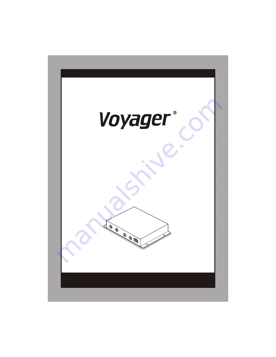
MULTI CAMERA CONTROLLER FOR
OBSERVATION MONITOR
(MULTIPLE DISPLAY MODE)
* PLEASE READ CAREFULLY BEFORE USING.
t
Co
o
o
n r
l B
x
Doc.Rev (200
7
/05/07)
Doc.Rev (200
7
/05/07)
Содержание Voyager CSW5007Q
Страница 14: ...Printed in Korea Printed in Korea ...