background image

Jennic

USB Programming Dongle 
Reference Manual 


2 Hardware Overview 

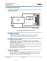
2.1 Board Layout 


J6:  USB

Connector

12

5

15

24

Dimensions in mm

U3: USB

Interface

Device

LED D2

RX

LED  D1

TX

pin 1

J8

26

J1

pin 1


Figure 2: USB Programming Dongle Layout 

2.2 USB Connection 

The USB connector is a standard USB Type A male connector. This allows 
connection to the power and serial data connections from the USB host. 

2.3 USB Interface Device 

The USB interface device is an FTDI FD232RL device. It is used to interface 
between the data connections of the USB port and the standard UART connections 
for UART0 of the JN5148 device. 

For details of installing the royalty-free FTDI device driver, refer to the 

JN51xx Flash 

Programmer User Guide (JN-UG-3007)

Once the device driver is installed, the USB Programming Dongle will appear as an 
additional COM port on the Windows PC. 

2.4 Power Supply 

The power for the USB Programming Dongle is sourced from the 5V connection on 
the USB connector.  The USB interface device generates a 3.3V supply which is 
available on the Primary connector, J8 (see Section 2.6).  

JN-RM-2056 v1.0 

© Jennic 2010 

Содержание JN5148

Страница 1: ...USB Programming Dongle Reference Manual JN RM 2056 Revision 1 0 24 Mar 2010...

Страница 2: ...Jennic USB Programming Dongle Reference Manual 2 Jennic 2010 JN RM 2056 v1 0...

Страница 3: ...ack Address 4 1 Introduction 5 1 1 Overview 5 1 2 Features 6 1 3 Reference Design 6 2 Hardware Overview 7 2 1 Board Layout 7 2 2 USB Connection 7 2 3 USB Interface Device 7 2 4 Power Supply 7 2 5 LED...

Страница 4: ...detailed feature information Chapter 3 describes how to program using the dongle Conventions Files folders functions and parameter types are represented in bold type Function parameters are represent...

Страница 5: ...lication code and program it into the device A standard Jennic evaluation kit uses an FTDI USB cable connected to a 6 pin header which connects to UART0 Switches are also required on the reset and SPI...

Страница 6: ...t JN5148 UART interface 1 3 Reference Design A Reference Design for the USB Programming Dongle board is available from the Support area of the Jennic web site www jennic com support This Reference Des...

Страница 7: ...FTDI FD232RL device It is used to interface between the data connections of the USB port and the standard UART connections for UART0 of the JN5148 device For details of installing the royalty free FTD...

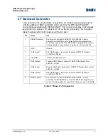
Страница 8: ...ote JN5148 i e DIO6 2 DIO7 output Transmit UART data to connect to UART0 RXD input of the JN5148 i e DIO7 3 MISO output Control line to connect to SPIMISO of the JN5148 used in conjunction with RESETN...

Страница 9: ...Also used to reset the JN5148 after a programming cycle It is only possible to cause this pin to go low due to the diode D4 2 GND Ground 3 DIO5 input CTS UART signal to connect to remote UART0 RTS out...

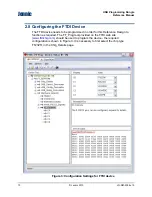
Страница 10: ...grammed in order for this Reference Design to function as required The FT_Prog tool provided on the FTDI web site www ftdichip com should be used to program the device the required configuration is sh...

Страница 11: ...board Pin 4 can also be connected if it is required to power the application board The JN51xx Flash programmer can then be used to program the Flash device see the JN51xx Flash Programmer User Guide J...

Страница 12: ...Jennic USB Programming Dongle Reference Manual 12 Jennic 2010 JN RM 2056 v1 0...

Страница 13: ...Jennic USB Programming Dongle Reference Manual Revision History Version Date Description 1 0 24 Mar 2010 First release JN RM 2056 v1 0 Jennic 2010 13...

Страница 14: ...ce support or customer product design Jennic assumes no responsibility or liability for the use of any of its products conveys no license or title under any patent copyright or mask work rights to the...

Отзывы: