background image


JEFF ROWLAND

D

E

S

I

G

N


G

R

O

U

P

Содержание Model 2

Страница 1: ...JEFF ROWLAND D E S I G N G R O U P ...

Страница 2: ...Model 2 Stereo Power Amplifier Owner s Manual ...

Страница 3: ...res will allow you to gain the maximum performance and ease of use for which this Amplifier was designed Please note that your Model 2 Stereo Amplifier serial number begins with the letter A þ This number is recorded below and is also located on the rear panel of the chassis þ Please include this number with any correspondence regarding your Model 2 Amplifier þ It has been my joy to create an audi...

Страница 4: ...perature stabilizing circuitry maintains constant operating temperature þ Standby power condition reduces warm up time þ Fail safe operation provided by user resetable AC circuit breaker located on rear panel þ Quiet transient free operation during power and function mode switching þ Automatic input muting under anomalous input or output operating conditions þ Balanced Differential Mode circuit to...

Страница 5: ...1 2 3 4 5 6 Contents ...

Страница 6: ... save all packing materials If the Amplifier is returned to your dealer or Jeff Rowland Design Group the original packing materials must be used for shipment Neither Jeff Rowland Design Group nor the shipper can be held responsible for damages incurred during transit if the original factory packing is not used All factory returns require that a Return Authorization number be issued by Jeff Rowland...

Страница 7: ...Front Rear Panel Function Controls A 1 2 ...

Страница 8: ...rnal circuitry is reverted to power saving standby mode Note All ON OFF power switching should be initiated ONLY with this button Anomalous operating conditions will automatically switch the Amplifier off no illumination and will prevent the Amplifier from being switched back on again until such a condition is eliminated Rear Panel Note The switches described below can be switched if desired while...

Страница 9: ...2 1 3 Rear Panel Power Connections ...

Страница 10: ...re is poor the Amplifier chassis can be loosely coupled to the supporting structure via the compliant isolation interface supports This will help attenuate the transfer of spurious energy from the supporting structure into the Amplifier chassis Note Another installation option when incorporating the optional Battery Power Source utilizes its chassis as a stable high mass structural support for the...

Страница 11: ...2 1 Signal Connections 4 3 3 ...

Страница 12: ...MINAL HAND WRENCH WHEN CONNECTING OR DISCONNECTING LOUDSPEAKER CABLES DO NOT OVERTIGHTEN THESE TERMINALS WARNING Both positive and negative OUTPUTS of both channels are electrically active with respect to chassis and or system ground potential It is important that both of these outputs are electrically isolated from system ground potential This precludes the use of this Amplifier in certain loudsp...

Страница 13: ...ded that balanced signal source INPUT and LOW INPUT IMPEDANCE options are used This condition requires that the driving source component preamplifier is equipped with balanced outputs and sufficient output current to properly drive the input of the Model 2 when the LOW INPUT IMPEDANCE option is selected Most high quality solid state pream plifiers can satisfy these conditions and best results are ...

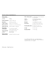
Страница 14: ...00 ohms Common Mode Rejection Ratio Greater than 60 dB 20 Hz to 20 kHz Power Consumption 25 watts standby 175 watts operating idle 400 watts maximum Inputs User selectable on rear panel Unbalanced With supplied XLR RCA adapter Balanced 2 XLR connectors Outputs 1 pair binding posts per channel Dimensions 17 5 in W x 14 25 in D x 5 25 in H 44 5 cm W x 36 2 cm D x 13 3 cm H Shipping Dimensions 24 in ...

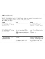
Страница 15: ...tening but can be returned to operational condition Cause Light bulb defective Incorrect power connections or AC MAINS CIRCUIT BREAKER on Amplifier rear panel is tripped Abnormal operation of Model 2 Amplifier internal circuitry Excessive sub sonic signals produced by source components Severe clipping of Amplifier circuitry under intermittent overload conditions Remedy Remove STANDBY POWER button ...

Страница 16: ...n loudspeakers Cause Internal DC fuses defective AC mains service voltage too high for Amplifier Sensitive source component s located too close to Amplifier Unstable conditions created by excessive capacitance in loudspeaker cables Remedy Consult dealer or JRDG Reconfigure Amplifier to proper AC mains voltage operation Consult dealer or JRDG Reorient or increase distance between source component a...

Страница 17: ...If you have any additional questions regarding installation or operation please contact your authorized Jeff Rowland Design Group Dealer JEFF ROWLAND D E S I G N G R O U P ...

Отзывы: