JBL Consumer Products Inc.
250 Crossways Park Drive
Woodbury, N.Y. 11797
1-800-336-4JBL in the USA
A Harman International Company
Rev C 11/2000
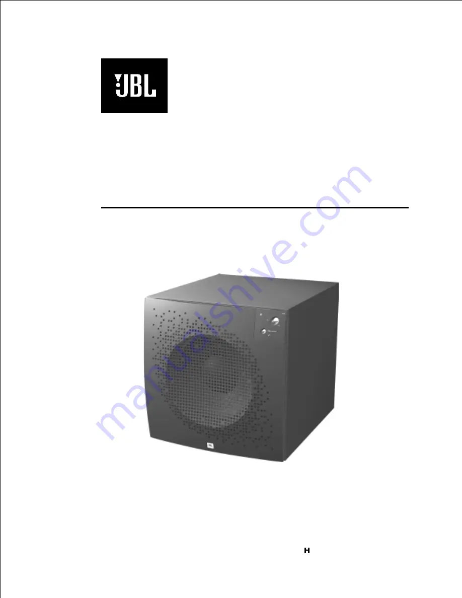
PSW-D115
Powered Subwoofer
SERVICE MANUAL
Страница 1: ...JBL Consumer Products Inc 250 Crossways Park Drive Woodbury N Y 11797 1 800 336 4JBL in the USA A Harman International Company Rev C 11 2000 PSW D115 Powered Subwoofer SERVICE MANUAL ...
Страница 2: ...ted Critical Components All components identified with the IEC symbol in the parts list and the schematic diagram designate components in which safety can be of special significance when replacing a component identified with Use only the replacement parts designated in the parts list or parts with the same rating of resistance wattage or voltage List of Safety Components Requiring Exact Replacemen...
Страница 3: ... 350 watts Driver 15 High Polymer Laminate Inputs Line Level and Speaker Level Outputs Line Level and Speaker Level Low Pass Frequency Continuously variable from 60Hz 180Hz High Pass Frequency Continuously variable from 60Hz 180Hz when using line level inputs 150Hz when using speaker level inputs Frequency Response 25Hz low pass crossover setting Dimensions H x W x D 20 x 20 x 21 3 4 508 x 508 x 5...
Страница 4: ... source Z 600 ohms Speaker Hi Level Input 7 Vrms 6 963 2dB To Rated Power Vol Max 1 input driven AP source Z 25 ohms Signal to Noise SNR A Weighted 100 dBA 102 90 Relative to rated output A Weighting filter SNR unweighted 75 dBr 85 70 Relative to rated output 22k filter SNR rel 1W unweighted 22k 65 dBr 67 55 relative to 1W Output 22k filter Residual Noise Floor 1 5 mVrms 1 1 5 Volume max using Aud...
Страница 5: ...al ck Nominal 200uF Series Cap on PCB Signal Present Level 60 mV 60 function al ck 100Hz into Line Input w 1 ch driven 2 2V Speaker in Signal Present Bandwidth 1k Hz function al ck Signal Present LPF for noise immunity Signal Present Turn on time 1 sec 0 5 function al ck Amp connected and AC on then input signal applied Auto Mute Turn OFF Time 15 min function al ck T before muting after signal is ...
Страница 6: ...t at 150Hz to main loudspeakers is desired through the Speaker Output Jacks 6 Speaker Out Jacks Connected to main loudspeakers when the Speaker Input Jacks are used 7 Phase Switch Changes the subwoofer s output to be in phase or 180 degrees out of phase with the program material 8 Line Input Main Input connection to subwoofer preferred 9 Direct In If you will be connecting the PSW D115 to a receiv...
Страница 7: ...f the low pass and high pass controls may evolve over several listening sessions A good starting point would be to set both the low and high pass controls to the same frequency and adjust from that point Low Pass Control The Low Pass control determines the highest frequency at which the subwoofer reproduces sounds If your main speakers can comfortably reproduce some low frequency sounds set this c...
Страница 8: ...end of the Y connector into the receiver amplifier and connect each of the 2 female connectors to an RCA type interconnect cable Then connect the 2 interconnect cables to the Left and Right line level inputs on the PSW D115 8 Amplifier Subwoofer PSW D115 60 90 150 180 120 60 90 150 180 120 180o 0o Phase Low Pass High Pass D i r e c t L I N E I N L I N E O U T Direct Out L C R L C R L C R SPKR In S...
Страница 9: ...to a variable low pass crossover When hooked up as shown the subwoofer will limit the low frequency information that is returned to your receiver amplifier Your receiver amplifier does not need to waste valuable power reproducing the low frequencies In addition since no low frequency information is being sent to your main loudspeakers they are able to reproduce mid and high frequencies with greate...
Страница 10: ...Control Switch to the opposite position n If you are using a Dolby Digital DTSÒ receiver or processor make sure that the subwoofer adjustments on the receiver processor are set up correctly n Slowly turn the level Control clockwise until you begin to hear the desired amount of bass If you used the line level inputs and there is no sound from the subwoofer check the following n Receiver amplifier i...
Страница 11: ... outer perimeter of the amplifier faceplate 3 Remove amplifier assembly you should be able to remove the amplifier far enough out of the cabinet to service it without removing the woofer wires 4 Locate the Power Amp Module it is the large gray component with a metal case On the solder side of the circuit board are the 28 soldered connections to the Module 5 Regardless of whether you can visibly se...
Страница 12: ...NOTE When testing the PSW D115 amplifier a load must always be connected to the output terminals whether the woofer or a 4 to 8 ohm resistive load ...
Страница 13: ...heck I P of module to GND 0V D C Power up with no signal I P LED RED OK OK OK OK OK OK OK OK Check C29 and Pre AMP Check O P to module for 80Vpp square wave measure to GND Check L1 L2 L3 L4 C6 C24 Check 6V to module measure to V Replace Module Power AMP OK END Check D1 R1 Q3 Q4 Q5 and SCP Check transformer CMC rectifier C1 C2 D9 D10 R16 R17 Check S D voltage to module 5V measure to V Check D6 R9 R...
Страница 14: ...PLODED VIEWS SCREWS 12 SCREWS 8 FEET 200582 CABINET NOT FOR SALE 15 WOOFER 200900 AMPLIFIER ASSEMBLY 200950 PSW D115 CABINET ASSEMBLY GRILLE with LOGO 200910 GRILLE SOCKETS 200790 VOLUME KNOB 70313 VIDEO CONT BUTTON 70314 VIDEO CONT SWITCH 70152 ...
Страница 15: ...1 5 Amplifier Subwoofer PSW D115 AMPLIFIER EXPLODED VIEW 5 5 4 4 3 3 2 2 1 1 A A B B C C D D E E F F G G PSW D115 Amplifier Assembly Exploded View 12 13 11 16 14 10 3 5 1 8 6 2 4 15 7 9 ...
Страница 16: ...switch PSW D115 5 70170 4x0 5 Screws to secure input jacks 6 70171 10 x 1 Machine screw Bolts for trans 4 7 70172 10 keps Nuts for transformer 4 8 70173 6 x 0 5 Screws for fuse PCB 2 9 80125 Transformer 4688 Safety part 10 80126 250V 3 0A T type SLO BLO fuse Safety part 11 80118 Preamp board PSW D115 Safety part 12 80119 Power amp board PSW D115 Safety part 13 80120 High level input PCB PSW D115 S...
Страница 17: ...fier Subwoofer PSW D115 PACKING EXPLODED VIEWS PSW D115 WARRANTY CARD OWNER S MANUAL 200930 120V 331993 001 TOP FOAM PAD 200922 STYROFOAM STICKS 4 200923 PSW D115 BOTTOM FOAM PAD 200921 CARTON 200920 PLASTIC BAG ...
Страница 18: ...1 8 Amplifier Subwoofer PSW D115 PSW D115 Version 3 21 PCB Component Side Version 3 2 Component Side Trace Layer 5 5 4 4 3 3 2 2 1 1 A A B B C C D D E E F F G G ...
Страница 19: ...1 9 Amplifier Subwoofer PSW D115 PSW D115 Version 3 21 PCB Solder Side Version 3 2 Solder Side Trace Layer as viewed through the board 5 5 4 4 3 3 2 2 1 1 A A B B C C D D E E F F G G ...
Страница 20: ...eramic axial 1 C8 13 14 15 30101 220pF 50V 20 Mono ceramic axial 4 C10 11 12 17 30502 100nF 50V 20 Mono ceramic axial 4 C16 30504 100nF 50V 10 Mono ceramic axial 1 C18 Jumper C19 30508 10nF 50V 10 Mono ceramic axial 1 C20 21 22 23 30504 100nF 50V 10 Mono ceramic axial 4 C24 C25 30501 47nF 50V 20 Mono ceramic axial 1 C26 30719 220uF 35V 80 20 Electrolytic Radial Diodes Signal LED 50109 Bi colour 1 ...
Страница 21: ...uits U4 60101 TL082 Dual Op Amp 1 60302 S64AMI Power Amp module 1 Safety Inductors CMC1 80100 mc4438 Safety part 1 L1 80121 mc4642 Safety part 1 L2 L3 L4 80122 Ferrite Bead 3 PSW D115 High Level Input Output Board R1 L R1 C 40406 100kW 0 25W 5 carbon film 6 R1 R R3 L R3 C R3 R R2 L R2 C 40405 4 7kW 0 25W 5 carbon film 3 R2 R C1 2 3 30704 220uF 50W 20 Electrolytic Radial 3 Revisions date issue deta...
Страница 22: ...THESE STEPS MAY RESULT IN THE INSTANT DESTRUCTION OF THE MODULE WHEN POWERED UP Align white indent marker on Amp Module with indent marker on main PCB alternately observe position of label on the top of the module incorrectly replacing the Module 180 in the PCB slot will result in its destruction All AC powered test instruments meters oscilloscopes etc must have a floating ground i e be connected ...
Страница 23: ...2 3 Amplifier Subwoofer PSW D115 PSW D115 SCHEMATIC 1 of 3 PWS D115 Schematic 1 of 3 5 5 4 4 3 3 2 2 1 1 A A B B C C D D E E F F G G ...
Страница 24: ...2 4 Amplifier Subwoofer PSW D115 PSW D115 SCHEMATIC 2 of 3 PWS D115 Schematic 2 of 3 E E D D C C B B A A 7 7 6 6 5 5 4 4 3 3 2 2 1 1 ...
Страница 25: ...2 5 Amplifier Subwoofer PSW D115 PSW D115 SCHEMATIC 3 of 3 PWS D115 Schematic 3 of 3 5 5 4 4 3 3 2 2 1 1 A A B B C C D D E E F F G G 3 0A ...