Rev-B
Page
7
of
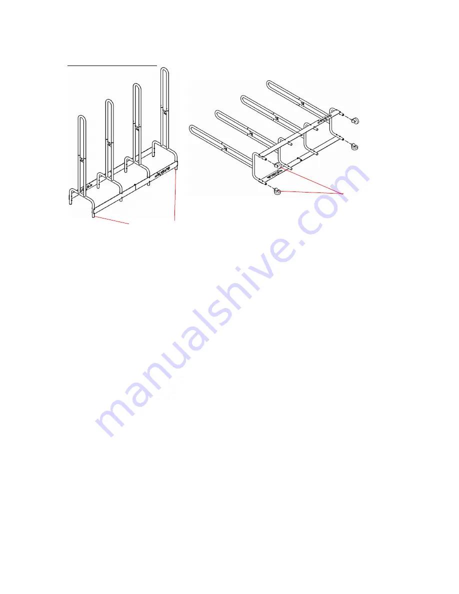
III. Install Wheels:
Figure 6
1)
Carefully lay the entire frame onto its side.
2)
Thread four wheels by hand onto the outside uprights. Please note only two of the uprights accept wheels.
OUTSIDE UPRIGHT
(w/ WHEEL MOUNTS)
WHEEL
Страница 1: ...Rev B Page 1 of 7 SP4 SHOULDER PAD Installation Instructions Call Jaypro Sports Equipment at 1 800 243 0533 during regular business hours for technical support www jaypro com ...
Страница 2: ...1 2 5 SIDE PLATE 2 PLATE w LOGO CUTOUT 2 6 WHEEL IMAGE MAY DIFFER FROM WHAT S SHOWN 4 7 8 x 12 PAN HEAD PHILIP SCREW 8 8 5 16 18 x 2 LONG BUTTON HD SCREW IMAGE MAY DIFFER FROM WHAT S SHOWN 16 9 5 16 18 x 1 LONG BUTTON HD SCREW IMAGE MAY DIFFER FROM WHAT S SHOWN 4 10 5 16 18 THIN NYLON LOCK NUT IMAGE MAY DIFFER FROM WHAT S SHOWN 20 ITEM IMAGE DESCRIPTION QTY ...
Страница 3: ... AS SERIOUS INJURY OR DAMAGE TO THE EQUIPMENT MAY OCCUR 3 USE OF THIS EQUIPMENT OTHER THAN INTENDED MAY BE HAZARDOUS 4 ALTERATION OR MODIFICATION OF THIS EQUIPMENT MAY BE HAZARDOUS AND RESULT IN INJURY FOR REPAIR OR REPLACEMENT CONTACT YOUR DEALER OR JAYPRO SPORTS Tools Require 1 Allen Wench Set 1 1 2 Socket or Adjustable Wench 1 Philips Screw Driver o Unpack all parts and check against parts list...
Страница 4: ...E OUTWARD SIDE PLATE 1 FLANGE SIDE PLATE 2 w LOGO CUTOUT 5 16 18 x 2 LONG BUTTON HD SCREW OUTSIDE UPRIGHT LOGO TO FACE OUTWARD 8 x 12 PAN HEAD PHILIP SCREW TOP UPRIGHT BOTTOM UPRIGHT w WHEEL MOUNTS 5 16 18 THIN NYLON LOCK NUT SIDE PLATE UPRIGHT NOTE ORIENTATION OF SIDE PLATE FLANGES ...
Страница 5: ... long button head screws as shown in Figure 1 Ensure that both upright logo faces the same direction and both side plate flanges are on the same side 2 Using 5 16 18 thin nylon lock nut To secure side plates to the uprights onto eight places as shown in Figure 2 3 Repeat steps again to create another set Figure 3 ...
Страница 6: ...alves of cart back to back Figure 4 and line up the holes in the side plate flange 2 Secure both halves together using 5 16 18 x 1 long button head screw and 5 16 18 thin nylon lock nut as shown in Figure 5 5 16 18 THIN NYLON LOCK NUT SIDE PLATE 5 16 18 x 1 LONG BUTTON HEAD SCREW ...
Страница 7: ... III Install Wheels Figure 6 1 Carefully lay the entire frame onto its side 2 Thread four wheels by hand onto the outside uprights Please note only two of the uprights accept wheels OUTSIDE UPRIGHT w WHEEL MOUNTS WHEEL ...