


www.javad.com
Maxor User’s Manual
2-17
C O N F I G U R A T I O N
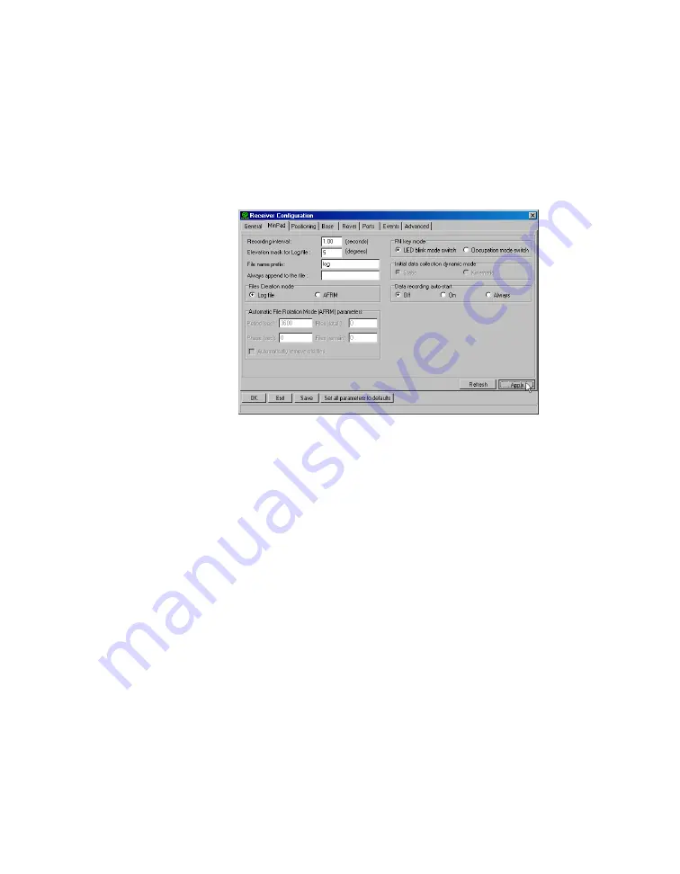
MinPad Configuration
•
Files Creation mode on page 2-18
•
Automatic File Rotation Mode (AFRM) on page 2-18
•
FN key mode on page 2-19
•
Initial data collection dynamic mode on page 2-19
•
Data recording auto-start on page 2-20
Figure 2-21. Receiver Configuration – MinPad Tab
Recording Interval parameter
This parameter specifies the message output interval into the log file when
the MinPad FN key (pressed for 1-5 seconds) activates data logging. This
setting is used not only when logging a single log file, but also when logging
receiver data in AFRM mode. Values are 1-86400 seconds.
The default value is one second.
Elevation Mask for Log File parameter
This parameter specifies the minimum elevation angle for the satellites
whose data will be put in the receiver files logged when pressing FN.
The default value is five degrees.
File Name Prefix parameter
This parameter specifies what prefix will be added to the names of the
receiver files created when pressing FN. The prefix can be up to 20
characters long.
The default value is log.
Содержание Maxor
Страница 1: ...Maxor GNSS Receiver User s Manual Copyright Javad Navigation Systems Inc March 2004...
Страница 2: ......
Страница 8: ...VI Maxor User s Manual www javad com Notes...
Страница 12: ...X Maxor User s Manual www javad com LIST OF FIGURES RS 232C Connector B 10 USB Connector B 11...
Страница 20: ...XVIII Maxor User s Manual www javad com Notes...
Страница 70: ...2 36 Maxor User s Manual www javad com Notes...
Страница 138: ...E 2 Maxor User s Manual www javad com Notes...
Страница 142: ...Index Maxor User s Manual www javad com Notes...


