background image

DTC P0826 MANUAL MODE SWITCH CIRCUIT

AT-589

[RE5F22A]

D

E

F

G

H

I

J

K

L

M

A

B

AT

Revision: November 2006

2006 Altima

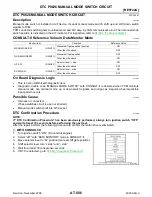
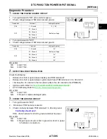
Diagnostic Procedure

ECS009I5

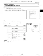
1. 

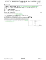
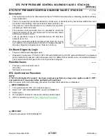
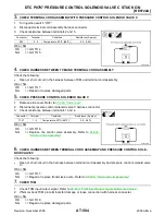
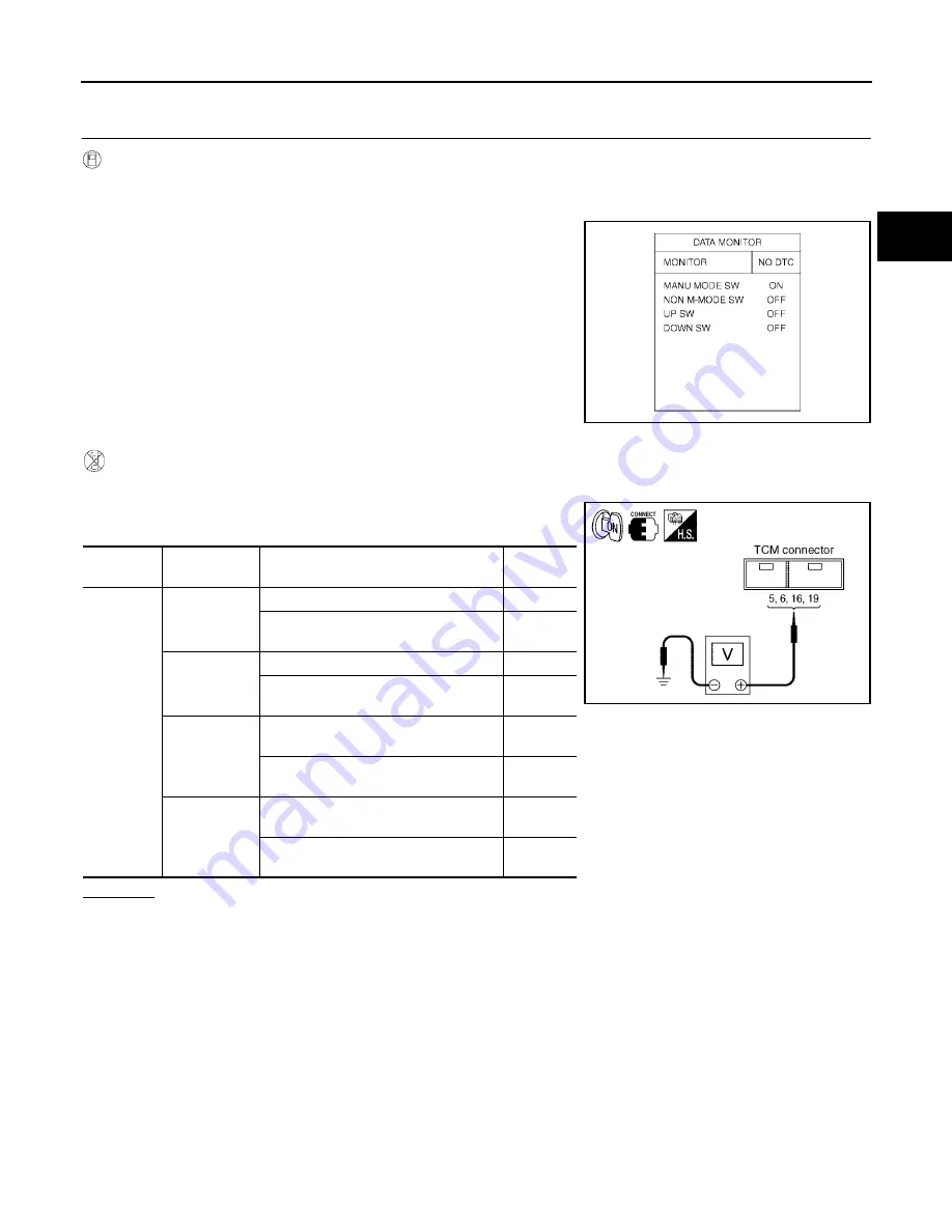
CHECK MANUAL MODE SWITCH CIRCUIT

 With CONSULT-II

1.

Turn ignition switch “ON”. (Do not start engine.)

2.

Select “A/T” with “DATA MONITOR” mode in CONSULT-II.

3.

Read out ON/OFF switching action of the “MANU MODE SW”,
“NON M-MODE SW”, “UP SW”, “DOWN SW”.

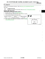
 Without CONSULT-II

1.

Turn ignition switch “ON”. (Do not start engine.)

2.

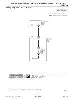
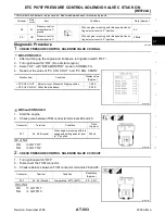
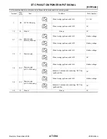
Check voltage between the TCM connector terminals and
ground.

OK or NG

OK

>> GO TO 4.

 NG

>> GO TO 2.

SCIA2917E

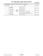
Connector 

No.

Terminal

Condition

Voltage 

(Approx.)

F56

5 - Ground

Selector lever: + side

0V

Other than the above

Battery 
voltage

6 - Ground

Selector lever: - side

0V

Other than the above

Battery 
voltage

16 - Ground

Selector lever: “P”, “R”, “N” or “D” posi-
tion

0V

Selector lever: Manual shift gate posi-
tion

Battery 
voltage

19 - Ground

Selector lever: Manual shift gate posi-
tion (neutral)

0V

Other than the above

Battery 
voltage

SCIA2918E

Содержание RE4F04B

Страница 1: ...r Lamp MIL 48 CONSULT II Function TCM 48 Diagnostic Procedure Without CONSULT II 59 TROUBLE DIAGNOSIS INTRODUCTION 64 Introduction 64 Work Flow 68 TROUBLE DIAGNOSIS BASIC INSPECTION 71 A T Fluid Check...

Страница 2: ...Pro cedure 158 Wiring Diagram AT TCCSIG 160 Diagnostic Procedure 161 DTC P0745 LINE PRESSURE SOLENOID VALVE 166 Description 166 On Board Diagnosis Logic 166 Possible Cause 166 Diagnostic Trouble Code...

Страница 3: ...elerate By Engine Brake 254 21 TCM Self diagnosis Does Not Activate PNP 3 Position Switches Circuit Checks and Throttle Position Sensor Accelerator Pedal Position APP Sensor Circuit Check 254 A T SHIF...

Страница 4: ...34 A T Electrical Parts Location 439 Circuit Diagram 440 Inspections Before Trouble Diagnosis 441 Check Before Engine is Started 445 Check at Idle 445 Cruise Test Part 1 447 Cruise Test Part 2 448 Cru...

Страница 5: ...Diagram AT 5THSIG 525 Diagnostic Procedure 527 DTC P0744 A T TCC S V FUNCTION LOCK UP 529 Description 529 On Board Diagnosis Logic 529 Possible Cause 529 DTC Confirmation Procedure 529 Wiring Diagram...

Страница 6: ...does not come on 598 Engine Cannot Be Started In P or N Position 600 In P Position Vehicle Moves When Pushed 600 In N Position Vehicle Moves 601 Large Shock N to D Position 602 Vehicle Does Not Creep...

Страница 7: ...embly 2 686 SERVICE DATA AND SPECIFICATIONS SDS 702 General Specifications 702 Shift Schedule 702 Stall Speed 703 Line Pressure 704 Time Lag 704 Shift Solenoid Valves 704 Solenoid Valves 704 Clutch an...

Страница 8: ...evolution sensor signal and the Vehicle speed sensor signal meet the fail safe condition at the same time Items CONSULT II screen terms DTC Reference page CONSULT II GST 1 A T 1ST GR FNCTN P0731 AT 13...

Страница 9: ...time DTC Items CONSULT II screen terms Reference page CONSULT II GST 1 P0705 PNP SW CIRC AT 110 P0710 ATF TEMP SEN CIRC AT 116 P0720 VEH SPD SEN CIR AT 3 AT 122 P0725 ENGINE SPEED SIG AT 127 P0731 A T...

Страница 10: ...d to in this Service Manual SRS wiring harnesses can be identified by yellow and or orange harnesses or harness connectors Precautions for On Board Diagnostic OBD System of A T and Engine ECS0095L The...

Страница 11: ...be carefully cleaned with a general purpose non flammable solvent before inspection or reassembly Gaskets seals and O rings should be replaced any time the transaxle is disassembled It is very importa...

Страница 12: ...Internal failure of stator roller clutch Heavy clutch debris due to overheating blue converter Steel particles or clutch lining material found in fluid filter or on magnet when no internal parts in un...

Страница 13: ...2006 Altima For details of OBD II refer to EC 53 ON BOARD DIAGNOSTIC OBD SYSTEM Certain systems and components especially those related to OBD may use a new style slide locking type harness connector...

Страница 14: ...erential side oil seal RH side Installing oil seal on oil pump housing a 60 mm 2 36 in dia b 47 mm 1 85 in dia J 34301 C Oil pressure gauge set 1 J 34301 1 Oil pressure gauge 2 J 34301 2 Hoses 3 J 342...

Страница 15: ...r race Installing idler gear bearing inner race a 67 5 mm 2 657 in dia b 44 mm 1 73 in dia c 38 5 mm 1 516 in dia ST30720000 J 25405 and J 34331 Bearing installer Installing idler gear bearing outer r...

Страница 16: ...b 28 5 mm 1 122 in dia c 130 mm 5 12 in d 135 mm 5 31 in e 100 mm 3 94 in ST3127S000 J 25765 A Preload gauge 1 GG91030000 J 25765 A Torque wrench 2 HT62940000 Socket adapter 3 HT62900000 Socket adapte...

Страница 17: ...moving reduction gear bearing inner race a 60 mm 2 36 in dia b 35 mm 1 38 in dia Drift Installing needle bearing on bearing retainer a 36 mm 1 42 in dia Drift Removing needle bearing from bearing reta...

Страница 18: ...eed for five minutes 7 Check fluid level and condition Refer to AT 398 Checking A T Fluid If the fluid is still contaminated repeat step 2 through 5 Checking A T Fluid ECS00EMR 1 Warm up the engine 2...

Страница 19: ...e reading on the gauge and will keep the gauge in position while driving 6 Check the fluid for the following conditions If the fluid is very dark or smells burned refer to AT 71 TROUBLE DIAGNOSIS BASI...

Страница 20: ...shop rag around the air gun tip and of the cooler outlet hose 9 Blow compressed air regulated to 5 9 kg cm2 70 130 psi through the cooler outlet hose for 10 sec onds to force out any remaining fluid...

Страница 21: ...5 Tie a common white basket type coffee filter to the end of the cooler inlet hose 6 Insert the tip of an air gun into the end of the cooler outlet hose 7 Wrap a shop rag around the air gun tip and en...

Страница 22: ...r peeled clutch facing material is found in the coffee filter the fluid cooler is not serviceable The A T fluid cooler radiator must be replaced and the inspection procedure is ended Refer to CO 13 RA...

Страница 23: ...OVERALL SYSTEM AT 23 RE4F04B D E F G H I J K L M A B AT Revision November 2006 2006 Altima OVERALL SYSTEM PFP 00000 A T Electrical Parts Location ECS0095R WCIA0474E...

Страница 24: ...AT 24 RE4F04B OVERALL SYSTEM Revision November 2006 2006 Altima Circuit Diagram ECS0095S BCWA0481E...

Страница 25: ...using 4 Oil pump 5 Brake band 6 Reverse clutch 7 High clutch 8 Front planetary gear 9 Low one way clutch 10 Rear planetary gear 11 Forward clutch 12 Overrun clutch 13 Low reverse brake 14 Output gear...

Страница 26: ...AT 26 RE4F04B OVERALL SYSTEM Revision November 2006 2006 Altima Hydraulic Control Circuit ECS0095U LCIA0040E...

Страница 27: ...to front sun gear 7 High clutch 6 H C To transmit input power to front planetary carrier 10 Forward clutch 15 F C To connect front planetary carrier 10 with forward one way clutch 16 Overrun clutch 1...

Страница 28: ...et in 3 position O Operates A Operates when throttle opening is less than 3 16 activating engine brake B Operates during progressive acceleration C Operates but does not affect power transmission D Op...

Страница 29: ...N Positions P position Similar to the N position the clutches do not operate The parking pawl engages with the parking gear to mechanically hold the output shaft so that the power train is locked N po...

Страница 30: ...ay clutch Forward one way clutch Overrun clutch Low and reverse brake As overrun clutch engages rear internal gear is locked by the operation of low and reverse brake This is different from that of D1...

Страница 31: ...Low one way clutch Rear internal gear is locked to rotate counterclockwise because of the functioning of these three clutches Overrun clutch engagement conditions Engine brake D1 Overdrive control swi...

Страница 32: ...otates around front sun gear accompanying front planetary carrier As front planetary carrier transfers the power to rear internal gear through forward clutch and forward one way clutch this rotation o...

Страница 33: ...lanetary carrier through high clutch And front planetary carrier is connected to rear internal gear by operation of forward clutch and forward one way clutch This rear internal gear rotation and anoth...

Страница 34: ...ower transmission Input power is transmitted to front carrier through high clutch This front carrier turns around the sun gear which is fixed by brake band and makes front internal gear output turn fa...

Страница 35: ...brake Front planetary carrier is stationary because of the operation of low and reverse brake Input power is transmitted to front sun gear through reverse clutch which drives front inter nal gear in t...

Страница 36: ...ition APP signal Engine speed signal A T fluid temperature sensor Revolution sensor Vehicle speed signal 3 position switch ASCD control signal Stop lamp switch Turbine revolution sensor power train re...

Страница 37: ...gnal which prohibits a shift to D4 overdrive position to the TCM ASCD control signal Sends the cruise signal and D4 overdrive cancellation signal from ASCD control unit to TCM Stop lamp switch Send th...

Страница 38: ...h operation Back up Control Engine brake If the selector lever is shifted to 2 position while driving in D4 O D or D3 great driving force is applied to the clutch inside the transmis sion Clutch opera...

Страница 39: ...hift is regulated entirely by electronic control to accommodate vehicle speed and varying engine opera tions This is accomplished by electrical signals transmitted by the revolution sensor and the ECM...

Страница 40: ...l which controls the lock up piston Conditions for Lock up Operation When vehicle is driven in 4th gear position vehicle speed and throttle opening are detected If the detected values fall within the...

Страница 41: ...hen the OFF duration of the torque converter clutch solenoid valve is short pilot pressure drains and becomes low Accordingly the control valve moves to the right by the pilot pressure of the other ci...

Страница 42: ...ntrol valve remains pushed down so that the overrun clutch is engaged at all times Control Valve ECS0095Y FUNCTION OF CONTROL VALVES SAT015J SAT016J Valve name Function Pressure regulator valve plug a...

Страница 43: ...positions line pressure acts on the overrun clutch reducing valve to increase the pressure regulating point with resultant engine brake capability Torque converter relief valve Prevents an excessive...

Страница 44: ...ed during the first test drive the MIL will illuminate and the malfunction will be stored in the ECM memory as a DTC The TCM is not provided with such a memory function TWO TRIP DETECTION LOGIC When a...

Страница 45: ...ta stored together with the DTC data are called freeze frame data and displayed on CONSULT II or GST The 1st trip freeze frame data can only be displayed on the CONSULT II screen not on the GST For de...

Страница 46: ...M memory when erasing DTC related to OBD II For details refer to Hyper link Error Diagnostic trouble codes DTC 1st trip diagnostic trouble codes 1st trip DTC Freeze frame data 1st trip freeze frame da...

Страница 47: ...9 OBD II SELF DIAG NOSTIC PROCEDURE NO TOOLS The engine warm up step can be skipped when performing the diagnosis only to erase the DTC 3 Select Mode 4 with Generic Scan Tool GST For details refer to...

Страница 48: ...II display If the difference is noticeable mechanical parts except solenoids sensors etc may be malfunctioning Check mechanical parts using applicable diagnostic procedures 2 Shift schedule which impl...

Страница 49: ...C Available by A T check position indicator lamp or A T on CONSULT II Available by malfunc tion indicator lamp 2 ENGINE on CONSULT II or GST A T ENGINE Park neutral position PNP switch circuit TCM doe...

Страница 50: ...valve X P0745 LINE PRESSURE S V L PRESS SOL CIRC Throttle position sensor accelerator pedal position APP sensor TCM receives an excessively low or high voltage from this sensor X P1705 THROTTLE POSI S...

Страница 51: ...om puted from signal of revolution sensor is displayed When racing engine in N or P with vehicle stationary CON SULT II data may not indicate 0 km h 0 mph Vehicle speed sensor 2 Meter VHCL S SE MTR km...

Страница 52: ...F X Status of ASCD OD release signal is dis played ON OD released OFF OD not released Kickdown switch KICKDOWN SW ON OFF X ON OFF status computed from sig nal of kickdown SW is displayed This is displ...

Страница 53: ...is shorted Shift solenoid valve B SHIFT S V B ON OFF X Control value of shift solenoid valve B computed by TCM from each input sig nal is displayed Overrun clutch sole noid valve OVERRUN C S V ON OFF...

Страница 54: ...NSULT II CONVERTER to data link connector which is located in left side dash panel 3 Turn ignition switch ON Do not start engine 4 Touch START NISSAN BASED VHCL Frequency Hz Value measured by pulse pr...

Страница 55: ...G H I J K L M A B AT Revision November 2006 2006 Altima 5 Touch A T If AT is not indicated go to GI 39 Consult II Data Link Con nector DLC Circuit 6 Touch DTC WORK SUPPORT 7 Touch select item menu 1ST...

Страница 56: ...ving test according to DTC CONFIRMATION PRO CEDURE in TROUBLE DIAGNOSIS FOR DTC When testing conditions are satisfied CONSULT II screen changes from OUT OF CONDITION to TESTING 10 Stop vehicle If NG a...

Страница 57: ...ber 2006 2006 Altima 11 Perform test drive to check gear shift feeling in accordance with instructions displayed 12 Touch YES or NO 13 CONSULT II procedure ended If NG appears on the screen a malfunct...

Страница 58: ...t 3RD GR FNCTN P0733 Following items for A T 3rd gear function P0733 can be con firmed Self diagnosis status whether the diagnosis is being conducted or not Self diagnosis result OK or NG Shift soleno...

Страница 59: ...rn ignition switch ON Do not start engine 4 Touch START NISSAN BASED VHCL 5 Touch A T If AT is not indicated go to GI 39 Consult II Data Link Con nector DLC Circuit 6 Touch CAN DIAGNOSTIC SUPPORT MONI...

Страница 60: ...n switch to ON position Do not start engine 5 Does A T check position indicator lamp come on for about 2 seconds Yes or No Yes GO TO 2 No Stop procedure Perform AT 217 1 A T Check Posi tion Indicator...

Страница 61: ...A0458E A T check position indicator lamp All judgement flickers are the same All circuits that can be confirmed by self diagnosis are OK 1st judgement flicker is longer than others Revolution sensor c...

Страница 62: ...circuited or disconnected Go to AT 153 DTC P0740 TORQUE CONVERTER CLUTCH SOLENOID VALVE 8th judgement flicker is longer than others A T fluid temperature sensor is disconnected or TCM power source ci...

Страница 63: ...urns off Park neutral position PNP switch and 3 position switch circuit is disconnected or TCM is damaged Go to AT 254 21 TCM Self diagnosis Does Not Activate PNP 3 Position Switches Circuit Checks an...

Страница 64: ...diagnose a problem that occurs intermit tently rather than continuously Most intermittent problems are caused by poor electric connections or improper wiring In this case careful checking of suspecte...

Страница 65: ...e Incident Date Manuf Date In Service Date Frequency Continuous Intermittent times a day Symptoms Vehicle does not move Any position Particular position No up shift 1st 2nd 2nd 3rd 3rd 4th No down shi...

Страница 66: ...AT 78 4 1 Check before engine is started AT 80 SELF DIAGNOSTIC PROCEDURE Mark detected items Park neutral position PNP switch AT 110 A T fluid temperature sensor AT 116 Vehicle speed sensor A T Revol...

Страница 67: ...Speed Does Not Return To Idle Engine Brake In 22 AT 248 19 A T Does Not Shift 22 11 When Selector Lever 2 1 Position AT 253 20 Vehicle Does Not Decelerate By Engine Brake AT 254 SELF DIAGNOSTIC PROCED...

Страница 68: ...tant to fully understand the symptoms or conditions for a customer complaint Make good use of the two sheets provided AT 65 Information from Customer and AT 66 Diagnostic Work sheet to perform the bes...

Страница 69: ...TRODUCTION AT 69 RE4F04B D E F G H I J K L M A B AT Revision November 2006 2006 Altima WORK FLOW CHART 1 AT 65 2 AT 66 3 AT 12 4 AT 71 5 AT 74 AT 77 6 AT 78 7 AT 48 8 AT 44 9 AT 44 10 AT 110 11 AT 211...

Страница 70: ...AT 70 RE4F04B TROUBLE DIAGNOSIS INTRODUCTION Revision November 2006 2006 Altima 13 AT 254 14 AT 93 15 AT 46 16 AT 110 17 AT 194 18 Hyper link Error Hyper link Error...

Страница 71: ...and friction material if present can become trapped in the A T fluid cooler This debris can con taminate the newly serviced A T or in severe cases can block or restrict the flow of A T fluid In eithe...

Страница 72: ...ound the air gun tip and of the cooler outlet hose 9 Blow compressed air regulated to 5 9 kg cm2 70 130 psi through the cooler outlet hose for 10 sec onds to force out any remaining fluid 10 Repeat st...

Страница 73: ...or 5 seconds 5 Tie a common white basket type coffee filter to the end of the cooler inlet hose 6 Insert the tip of an air gun into the end of the cooler outlet hose 7 Wrap a shop rag around the air g...

Страница 74: ...and engine oil levels If necessary add fluid and oil 2 Drive vehicle for approximately 10 minutes or until fluid and oil reach operating temperature 3 Set parking brake and block wheels 4 Install a t...

Страница 75: ...position and engine brake functions 1st and 2nd gears in 2 position and engine brake functions with accelerator pedal released fully closed throttle Forward clutch or forward one way clutch slippage S...

Страница 76: ...AT 76 RE4F04B TROUBLE DIAGNOSIS BASIC INSPECTION Revision November 2006 2006 Altima Poor acceleration during starts One way clutch seizure in torque converter SCIA3256E...

Страница 77: ...ling bolts LINE PRESSURE TEST PROCEDURE 1 Check A T fluid and engine oil levels If necessary add fluid and oil 2 Drive vehicle for approximately 10 minutes or until fluid and oil reach operating tempe...

Страница 78: ...or pressure regulator valve damaged Fluid pressure leakage between oil strainer and pres sure regulator valve Clogged strainer Line pressure is low in particular position Fluid pressure leakage betwee...

Страница 79: ...ma Before road test familiarize yourself with all test procedures and items to check Conduct tests on all items until specified symptom is found Troubleshoot items which check out No Good after road t...

Страница 80: ...Does A T check position OFF indicator lamp flicker for about 8 sec onds Yes or No Yes Perform self diagnosis and check NG items on the DIAGNOSTIC WORKSHEET AT 66 Refer to AT 60 TCM SELF DIAGNOSTIC PRO...

Страница 81: ...lever to P position 2 Turn ignition switch to OFF position 3 Release parking brake 4 Push vehicle forward or backward 5 Does vehicle move when it is pushed forward or backward 6 Apply parking brake Ye...

Страница 82: ...icle creep backward when foot brake is released Yes or No Yes GO TO 7 No Mark the box on the DIAGNOSTIC WORKSHEET Go to AT 225 6 Vehicle Does Not Creep Backward In R Position Continue ROAD TEST 7 CHEC...

Страница 83: ...edule Refer to AT 378 Shift Schedule CONSULT II Setting Procedure CAUTION If CONSULT II is used with no connection of CONSULT II CONVERTER malfunctions might be detected in self diagnosis depending on...

Страница 84: ...DATA MONITOR 7 Touch MAIN SIGNALS or TCM INPUT SIGNALS 8 See Numerical Display Barchart Display or Line Graph Dis play 9 Touch SETTING to set recording condition AUTO TRIG or MANU TRIG and touch BACK...

Страница 85: ...L M A B AT Revision November 2006 2006 Altima 12 After finishing cruise test part 1 touch STOP 13 Touch STORE and touch BACK 14 Touch DISPLAY 15 Touch PRINT 16 Check the monitor data printed out 17 C...

Страница 86: ...rk vehicle on flat surface 3 Set gear selector lever to D position 4 Move selector lever to P position 5 Start engine 6 Move selector lever to D position 7 Accelerate vehicle by constantly depressing...

Страница 87: ...cified speed Read gear position throttle opening and vehicle speed Yes or No Yes GO TO 4 No Go to AT 237 10 A T Does Not Shift D2 D3 Con tinue ROAD TEST 4 CHECK SHIFT UP D3 TO D4 Does A T shift from D...

Страница 88: ...up Condition 7 CHECK SHIFT DOWN D4 L U TO D4 1 Release accelerator pedal 2 Is lock up released when accelerator pedal is released Yes or No Yes GO TO 8 No Go to AT 247 14 Lock up Is Not Released Cont...

Страница 89: ...icle to 80 km h 50 MPH as shown in illustration 2 Release accelerator pedal and then quickly depress it fully 3 Does A T shift from D4 to D2 as soon as accelerator pedal is depressed fully Read gear p...

Страница 90: ...BRAKE Release accelerator pedal after shifting from D2 to D3 Does A T shift from D3 to D4 and does vehicle decelerate by engine brake Read gear position throttle opening and vehicle speed Yes or No Ye...

Страница 91: ...erator pedal 4 Move gear selector lever from D position to 3 position while driv ing in D4 5 Does A T shift from D4 to 3 Read gear position and vehicle speed Yes or No Yes GO TO 2 No Go to AT 251 17 A...

Страница 92: ...8 15 Engine Speed Does Not Return To Idle Light Braking D4 D3 Continue ROAD TEST 5 CHECK SHIFT DOWN 22 TO 11 1 Move selector lever from 2 to 1 position while driving in 22 2 Does A T shift from 22 to...

Страница 93: ...283 Torque converter clutch piston slip ON vehicle 1 Fluid level AT 71 2 Throttle position sensor accelerator pedal position APP sensor adjustment EC 81 3 Line pressure test AT 77 4 Torque converter...

Страница 94: ...lutch solenoid valve AT 185 4 Control valve assembly AT 267 Large shock changing from 12 to 11 in 1 posi tion ON vehicle 1 Control valve assembly AT 267 ON vehicle 2 Low reverse brake AT 334 Improper...

Страница 95: ...71 2 Throttle position sensor accelerator pedal position APP sensor adjustment EC 81 3 Overrun clutch solenoid valve AT 185 4 Shift solenoid valve A AT 172 5 Line pressure solenoid valve AT 166 6 Con...

Страница 96: ...sensor MTR AT 122 AT 201 3 Shift solenoid valve A AT 172 4 Control valve assembly AT 267 5 Overrun clutch solenoid valve AT 185 OFF vehicle 6 Overrun clutch AT 328 7 Low reverse brake AT 334 No Up Sh...

Страница 97: ...ution sensor and vehicle speed sensor MTR AT 122 AT 201 4 Shift solenoid valve A AT 172 5 Overrun clutch solenoid valve AT 185 6 Control valve assembly AT 267 7 A T fluid temperature sensor AT 116 8 L...

Страница 98: ...pedal position APP sensor adjustment EC 81 4 Line pressure test AT 77 5 Line pressure solenoid valve AT 166 6 Control valve assembly AT 267 7 Accumulator N D AT 283 OFF vehicle 8 Forward clutch AT 328...

Страница 99: ...rator pedal position APP sensor adjustment EC 81 3 Line pressure test AT 77 4 Line pressure solenoid valve AT 166 5 Control valve assembly AT 267 OFF vehicle 6 High clutch AT 324 7 Forward clutch AT 3...

Страница 100: ...er AT 283 10 Parking components AT 278 NOT USED Engine cannot be started in P and N positions AT 219 ON vehicle 1 Ignition switch and starter SC 11 2 Control cable adjustment AT 270 3 Park neutral pos...

Страница 101: ...tch AT 328 Excessive creep ON vehicle 1 Engine idling rpm EC 80 Engine stops when shifting lever into R D 2 and 1 ON vehicle 1 Engine idling rpm EC 80 2 Torque converter clutch solenoid valve AT 153 3...

Страница 102: ...269 2 Control cable adjustment AT 270 3 Throttle position sensor accelerator pedal position APP sensor adjustment EC 81 4 Vehicle speed sensor A T Revolution sensor and vehicle speed sensor MTR AT 12...

Страница 103: ...igh clutch AT 324 4 Brake band AT 283 5 Forward clutch AT 328 6 Overrun clutch AT 328 7 Low reverse brake AT 334 Offensive smell at fluid charging pipe ON vehicle 1 Fluid level AT 71 OFF vehicle 2 Tor...

Страница 104: ...ch OFF 0V 11 R Y Shift solenoid valve A When shift solenoid valve A operates When driving in D1 or D4 Battery volt age When shift solenoid valve A does not operate When driving in D2 or D3 0V 12 LG B...

Страница 105: ...er to R position Battery volt age When setting selector lever to other positions 0V 36 R B PNP switch P or N position When setting selector lever to P or N position Battery volt age When setting selec...

Страница 106: ...AT 106 RE4F04B TROUBLE DIAGNOSIS GENERAL DESCRIPTION Revision November 2006 2006 Altima CAN Communication ECS0096F For details refer to LAN 20 CAN COMMUNICATION...

Страница 107: ...TROUBLE DIAGNOSIS FOR POWER SUPPLY AT 107 RE4F04B D E F G H I J K L M A B AT Revision November 2006 2006 Altima TROUBLE DIAGNOSIS FOR POWER SUPPLY PFP 00000 Wiring Diagram AT MAIN ECS0096G BCWA0137E...

Страница 108: ...een TCM terminal 28 and ground OK or NG OK GO TO 4 NG GO TO 3 3 DETECT MALFUNCTIONING ITEM Check the following items Harness for short or open between ignition switch and TCM terminals 10 19 and 28 Fu...

Страница 109: ...GROUND CIRCUIT 1 Turn ignition switch to OFF position 2 Disconnect TCM harness connector 3 Check continuity between TCM terminals 25 48 and ground Refer to AT 107 Wiring Diagram AT MAIN OK or NG OK I...

Страница 110: ...g items Harness or connectors The park neutral position PNP switch circuit is open or shorted Park neutral position PNP switch Diagnostic Trouble Code DTC Confirmation Procedure ECS0096L CAUTION Alway...

Страница 111: ...DTC P0705 PARK NEUTRAL POSITION SWITCH AT 111 RE4F04B D E F G H I J K L M A B AT Revision November 2006 2006 Altima WITH GST Follow the procedure With CONSULT II...

Страница 112: ...AT 112 RE4F04B DTC P0705 PARK NEUTRAL POSITION SWITCH Revision November 2006 2006 Altima Wiring Diagram AT PNP SW ECS0096M WCWA0221E...

Страница 113: ...the selector lever position is indicated properly OK or NG OK GO TO 7 NG GO TO 3 TERMINAL WIRE COLOR ITEM CONDITION DATA APPROX 26 PU W PNP SWITCH 1 POSITION WHEN SETTING SELECTOR LEVER IN 1 POSITION...

Страница 114: ...manual control cable disconnected from manual shaft of A T assembly Refer to test group 1 OK or NG OK Adjust manual control cable Refer to AT 270 Control Cable Adjustment NG Repair or replace PNP swi...

Страница 115: ...selector lever through each position OK or NG OK GO TO 7 NG GO TO 5 7 CHECK DTC Perform AT 110 Diagnostic Trouble Code DTC Confirmation Procedure OK or NG OK INSPECTION END NG GO TO 8 8 CHECK TCM INSP...

Страница 116: ...TCM receives an excessively low or high voltage from the sensor Possible Cause ECS0096Q Check the following items Harness or connectors The sensor circuit is open or shorted A T fluid temperature sens...

Страница 117: ...ONITOR mode for A T with CONSULT II 2 Select ECM INPUT SIGNALS touch START 3 Start engine and maintain the following conditions for at least 10 minutes Total It is not necessary to maintain continuous...

Страница 118: ...AT 118 RE4F04B DTC P0710 A T FLUID TEMPERATURE SENSOR CIRCUIT Revision November 2006 2006 Altima Wiring Diagram AT FTS ECS0096S BCWA0139E...

Страница 119: ...006 2006 Altima TCM TERMINALS AND REFERENCE VALUE MEASURED BETWEEN EACH TERMINAL AND 25 OR 48 TCM GROUND TERMINAL WIRE COLOR ITEM CONDITION DATA APPROX 42 B SENSOR GROUND 47 G A T FLUID TEMPERATURE SE...

Страница 120: ...CORD ASSEMBLY 1 Turn ignition switch to OFF position 2 Disconnect terminal cord assembly connector in engine compartment 3 Check resistance between terminal cord F30 terminals 6 and 7 component side w...

Страница 121: ...UID TEMPERATURE SENSOR WITHOUT CONSULT II Without CONSULT II 1 Start engine 2 Check voltage between TCM terminal 47 and ground while warming up A T OK or NG OK GO TO 7 NG GO TO 3 7 CHECK DTC Perform A...

Страница 122: ...receive the proper voltage signal from the sensor Possible Cause ECS0096W Check the following items Harness or connectors The sensor circuit is open or shorted Revolution sensor Diagnostic Trouble Co...

Страница 123: ...19 MPH or more THRTL POS SEN More than 1 2V Selector lever D position Driving location Driving the vehicle uphill increased engine load will help maintain the driving conditions required for this tes...

Страница 124: ...AT 124 RE4F04B DTC P0720 VEHICLE SPEED SENSOR A T REVOLUTION SENSOR Revision November 2006 2006 Altima Wiring Diagram AT VSSA T ECS0096Y BCWA0140E...

Страница 125: ...K REVOLUTION SENSOR WITH CONSULT II With CONSULT II 1 Start engine Harness for short or open between TCM ECM and revolution sensor Main harness OK or NG OK GO TO 3 NG Repair or replace damaged parts 3...

Страница 126: ...SENSOR Revision November 2006 2006 Altima 4 CHECK TCM INSPECTION 1 Perform TCM input output signal inspection 2 If NG recheck TCM pin terminals for damage or loose connection with harness connector O...

Страница 127: ...rted Diagnostic Trouble Code DTC Confirmation Procedure ECS00973 CAUTION Always drive vehicle at a safe speed NOTE If DTC Confirmation Procedure has been previously conducted always turn ignition swit...

Страница 128: ...AT 128 RE4F04B DTC P0725 ENGINE SPEED SIGNAL Revision November 2006 2006 Altima Wiring Diagram AT ENGSS ECS00974 BCWA0141E...

Страница 129: ...Check ignition signal circuit for engine control Refer to EC 585 IGNITION SIGNAL 2 CHECK INPUT SIGNAL WITH CONSULT II With CONSULT II 1 Start engine 2 Select TCM INPUT SIGNALS in DATA MONITOR mode fo...

Страница 130: ...between TCM and ECM Resistor and ignition coil Refer to EC 585 IGNITION SIGNAL OK or NG OK GO TO 6 NG Repair or replace damaged parts 6 CHECK DTC Perform AT 127 Diagnostic Trouble Code DTC Confirmati...

Страница 131: ...ion will be caused when either shift solenoid valve A is stuck open or shift solenoid valve B is stuck open Gear positions supposed by TCM are as follows In case of gear position with no malfunctions...

Страница 132: ...y from a speed of 20 to 25 km h 12 to 16 MPH until TESTING changes to STOP VEHICLE or COM PLETED It will take approximately 3 seconds If the check result NG appears on CONSULT II screen go to AT 134 D...

Страница 133: ...DTC P0731 A T 1ST GEAR FUNCTION AT 133 RE4F04B D E F G H I J K L M A B AT Revision November 2006 2006 Altima Wiring Diagram AT 1STSIG ECS0097A LCWA0010E...

Страница 134: ...Shift solenoid valve A Shift solenoid valve B 2 Check solenoid valve by listening for its operating sound while applying battery voltage to the terminal and ground OK or NG OK GO TO 3 NG Repair or re...

Страница 135: ...g slide along valve bore under their own weight Valve sleeve and plug are free from burrs dents and scratches Control valve springs are free from damage deformation and fatigue Hydraulic line is free...

Страница 136: ...ecified value TCM judges this diagnosis malfunction This malfunction will be caused when shift solenoid valve B is stuck open Gear positions supposed by TCM are as follows In case of gear position wit...

Страница 137: ...I quickly from a speed of 45 to 50 km h 28 to 31 MPH until TESTING changes to STOP VEHICLE or COM PLETE It will take approximately 3 seconds If the check result NG appears on CONSULT II screen go to A...

Страница 138: ...AT 138 RE4F04B DTC P0732 A T 2ND GEAR FUNCTION Revision November 2006 2006 Altima Wiring Diagram AT 2NDSIG ECS0097G LCWA0011E...

Страница 139: ...nd while applying battery voltage to the terminal and ground OK or NG OK GO TO 3 NG Repair or replace shift solenoid valve assembly 3 CHECK CONTROL VALVE 1 Disassemble control valve assembly Refer to...

Страница 140: ...2ND GEAR FUNCTION Revision November 2006 2006 Altima 4 CHECK DTC Perform AT 136 Diagnostic Trouble Code DTC Confirmation Procedure OK or NG OK INSPECTION END NG Check control valve again Repair or re...

Страница 141: ...In case the ratio exceeds the specified value TCM judges this diagnosis malfunction This malfunction will be caused when shift solenoid valve A is stuck closed Gear positions supposed by TCM are as fo...

Страница 142: ...peed of 60 to 75 km h 37 to 47 MPH until TESTING changes to STOP VEHICLE or COMPLETED It will take approximately 3 seconds If the check result NG appears on CONSULT II screen go to AT 144 Diagnostic P...

Страница 143: ...DTC P0733 A T 3RD GEAR FUNCTION AT 143 RE4F04B D E F G H I J K L M A B AT Revision November 2006 2006 Altima Wiring Diagram AT 3RDSIG ECS0097M LCWA0012E...

Страница 144: ...ing battery voltage to the terminal and ground OK or NG OK GO TO 3 NG Repair or replace shift solenoid valve assembly 3 CHECK CONTROL VALVE 1 Disassemble control valve assembly Refer to AT 306 Control...

Страница 145: ...F04B D E F G H I J K L M A B AT Revision November 2006 2006 Altima 4 CHECK DTC Perform AT 141 Diagnostic Trouble Code DTC Confirmation Procedure OK or NG OK INSPECTION END NG Check control valve again...

Страница 146: ...ase the ratio does not reach the specified value TCM judges this diagnosis malfunction This malfunction will be caused when shift solenoid valve B is stuck closed Gear positions supposed by TCM are as...

Страница 147: ...at all times during step 4 Selector lever D position Check that GEAR shows 3 after releasing pedal 5 Depress accelerator pedal steadily with 1 0 8 2 0 8 of THROT TLE POSI from a speed of 55 to 65 km...

Страница 148: ...AT 148 RE4F04B DTC P0734 A T 4TH GEAR FUNCTION Revision November 2006 2006 Altima Wiring Diagram AT 4THSIG ECS0097S BCWA0142E...

Страница 149: ...N ACCELERATOR PEDAL IS RELEASED WHILE DRIVING 1 5 3 0V WHEN ACCELERATOR PEDAL IS DEPRESSED WHILE DRIVING 0V 2 W B LINE PRESSURE SOLENOID VALVE DROPPING RESIS TOR WHEN ACCELERATOR PEDAL IS RELEASED WHI...

Страница 150: ...the terminal and ground OK or NG OK GO TO 5 NG Replace solenoid valve assembly 5 CHECK CONTROL VALVE 1 Disassemble control valve assembly Refer to AT 306 Control Valve Assembly 2 Check to ensure that...

Страница 151: ...olenoid valve by listening for its operating sound while applying battery voltage to the terminal and ground OK or NG OK GO TO 9 NG Replace solenoid valve assembly 9 CHECK CONTROL VALVE 1 Disassemble...

Страница 152: ...R FUNCTION Revision November 2006 2006 Altima 11 CHECK DTC Perform AT 146 Diagnostic Trouble Code DTC Confirmation Procedure OK or NG OK INSPECTION END NG Perform Cruise test Part 1 again and return t...

Страница 153: ...E Remarks Specification data are reference values On Board Diagnosis Logic ECS0097V Diagnostic trouble code TCC SOLENOID CIRC with CONSULT II or P0740 without CONSULT II is detected when TCM detects a...

Страница 154: ...TC P0740 TORQUE CONVERTER CLUTCH SOLENOID VALVE Revision November 2006 2006 Altima 2 Select DATA MONITOR mode for A T with CONSULT II and wait at least 1 second WITH GST Follow the procedure With CONS...

Страница 155: ...DTC P0740 TORQUE CONVERTER CLUTCH SOLENOID VALVE AT 155 RE4F04B D E F G H I J K L M A B AT Revision November 2006 2006 Altima Wiring Diagram AT TCV ECS0097Y LCWA0014E...

Страница 156: ...sound while applying battery voltage to the terminal and ground Harness of terminal cord assembly for short or open OK or NG OK GO TO 3 NG Repair or replace damaged parts 3 CHECK POWER SOURCE CIRCUIT...

Страница 157: ...ECK DTC Perform AT 153 Diagnostic Trouble Code DTC Confirmation Procedure OK or NG OK INSPECTION END NG GO TO 5 5 CHECK TCM INSPECTION 1 Perform TCM input output signal inspection 2 If NG recheck TCM...

Страница 158: ...TCM supposes If the actual gear position is much lower than the position 4th supposed by TCM the slip ratio will be much less than normal In case the ratio does not reach the specified value TCM judge...

Страница 159: ...nd maintain the following condition continuously until TESTING has turned to COMPLETE It will take approximately 30 seconds after TESTING shows THROTTLE POSI 1 0 8 2 0 8 at all times during step 4 Sel...

Страница 160: ...AT 160 RE4F04B DTC P0744 A T TCC S V FUNCTION LOCK UP Revision November 2006 2006 Altima Wiring Diagram AT TCCSIG ECS00984 BCWA0143E...

Страница 161: ...Test OK or NG OK GO TO 3 NG GO TO 6 TERMINAL WIRE COLOR ITEM CONDITION DATA APPROX 1 G R LINE PRESSURE SOLENOID VALVE WHEN ACCELERATOR PEDAL IS RELEASED WHILE DRIVING 1 5 3 0V WHEN ACCELERATOR PEDAL I...

Страница 162: ...control valve 4 CHECK SHIFT UP D3 TO D4 Does A T shift from D3 to D4 at the specified speed OK or NG OK GO TO 5 NG Check control valve again Repair or replace control valve assembly 5 CHECK DTC Perfo...

Страница 163: ...Valve Assembly 2 Check line pressure circuit valves for sticking Pressure regulator valve Pilot valve Pressure modifier valve OK or NG OK GO TO 9 NG Repair control valve 9 CHECK SHIFT UP D3 TO D4 Does...

Страница 164: ...solenoid valve by listening for its operating sound while applying battery voltage to the terminal and ground OK or NG OK GO TO 14 NG Replace solenoid valve assembly 14 CHECK CONTROL VALVE 1 Disassemb...

Страница 165: ...D E F G H I J K L M A B AT Revision November 2006 2006 Altima 16 CHECK DTC Perform AT 158 Diagnostic Trouble Code DTC Confirmation Procedure OK or NG OK INSPECTION END NG Perform Cruise test Part 1 a...

Страница 166: ...ies to operate the solenoid valve Possible Cause ECS00988 Check the following items Harness or connectors The solenoid circuit is open or shorted Line pressure solenoid valve Diagnostic Trouble Code D...

Страница 167: ...SURE SOLENOID VALVE AT 167 RE4F04B D E F G H I J K L M A B AT Revision November 2006 2006 Altima 2 Depress accelerator pedal completely and wait at least 1 sec ond WITH GST Follow the procedure With C...

Страница 168: ...AT 168 RE4F04B DTC P0745 LINE PRESSURE SOLENOID VALVE Revision November 2006 2006 Altima Wiring Diagram AT LPSV ECS0098A BCWA0468E...

Страница 169: ...assembly Refer to AT 267 Control Valve Assembly and Accumulators 2 Check the following items Line pressure solenoid valve Check solenoid valve by listening for its operating sound while applying batte...

Страница 170: ...en TCM terminal 2 and terminal cord assembly Main harness OK or NG OK GO TO 5 NG Repair or replace damaged parts 5 CHECK POWER SOURCE CIRCUIT 1 Turn ignition switch to OFF position 2 Check continuity...

Страница 171: ...K L M A B AT Revision November 2006 2006 Altima 7 CHECK TCM INSPECTION 1 Perform TCM input output signal inspection 2 If NG recheck TCM pin terminals for damage or loose connection with harness conne...

Страница 172: ...the solenoid valve Possible Cause ECS0098E Check the following items Harness or connectors The solenoid circuit is open or shorted Shift solenoid valve A Diagnostic Trouble Code DTC Confirmation Proce...

Страница 173: ...ALVE A AT 173 RE4F04B D E F G H I J K L M A B AT Revision November 2006 2006 Altima 2 Start engine 3 Drive vehicle in D position and allow the transaxle to shift 1 2 GEAR WITH GST Follow the procedure...

Страница 174: ...AT 174 RE4F04B DTC P0750 SHIFT SOLENOID VALVE A Revision November 2006 2006 Altima Wiring Diagram AT SSV A ECS0098G LCWA0017E...

Страница 175: ...e by listening for its operating sound while applying battery voltage to the terminal and ground Harness of terminal cord assembly for short or open OK or NG OK GO TO 3 NG Repair or replace damaged pa...

Страница 176: ...2 Diagnostic Trouble Code DTC Confirmation Procedure OK or NG OK INSPECTION END NG GO TO 5 5 CHECK TCM INSPECTION 1 Perform TCM input output signal inspection 2 If NG recheck TCM pin terminals for dam...

Страница 177: ...es to operate the solenoid valve Possible Cause ECS0098K Check the following items Harness or connectors The solenoid circuit is open or shorted Shift solenoid valve B Diagnostic Trouble Code DTC Conf...

Страница 178: ...DTC P0755 SHIFT SOLENOID VALVE B Revision November 2006 2006 Altima 2 Start engine 3 Drive vehicle in D position and allow the transaxle to shift 1 2 3 GEAR WITH GST Follow the procedure With CONSULT...

Страница 179: ...DTC P0755 SHIFT SOLENOID VALVE B AT 179 RE4F04B D E F G H I J K L M A B AT Revision November 2006 2006 Altima Wiring Diagram AT SSV B ECS0098M LCWA0018E...

Страница 180: ...ning for its operating sound while applying battery voltage to the terminal and ground Harness of terminal cord assembly for short or open OK or NG OK GO TO 3 NG Repair or replace damaged parts 3 CHEC...

Страница 181: ...Perform AT 177 Diagnostic Trouble Code DTC Confirmation Procedure OK or NG OK INSPECTION END NG GO TO 5 5 CHECK TCM INSPECTION 1 Perform TCM input output signal inspection 2 If NG recheck TCM pin term...

Страница 182: ...es not receive the proper accelerator pedal position signals input via CAN communication from ECM Possible Cause ECS0098Q Harness or connectors The sensor circuit is open or shorted Diagnostic Trouble...

Страница 183: ...o ON position Do not start engine 2 Select TCM INPUT SIGNALS in DATA MONITOR mode for A T with CONSULT II 3 Read out the value of THROTTLE POSI OK or NG OK GO TO 4 NG GO TO 3 3 CHECK DTC WITH ECM With...

Страница 184: ...I TION APP SENSOR Revision November 2006 2006 Altima 5 CHECK TCM INSPECTION 1 Perform TCM input output signal inspection 2 If NG recheck TCM pin terminals for damage or loose connection with harness c...

Страница 185: ...Possible Cause ECS0098W Check the following items Harness or connectors The solenoid circuit is open or shorted Overrun clutch solenoid valve Diagnostic Trouble Code DTC Confirmation Procedure ECS0098...

Страница 186: ...VERRUN CLUTCH SOLENOID VALVE Revision November 2006 2006 Altima 5 Release accelerator pedal completely with selector lever in 3 position Verify operation of OVERRUN C S V WITH GST Follow the procedure...

Страница 187: ...DTC P1760 OVERRUN CLUTCH SOLENOID VALVE AT 187 RE4F04B D E F G H I J K L M A B AT Revision November 2006 2006 Altima Wiring Diagram AT OVRCSV ECS0098Y WCWA0053E...

Страница 188: ...alve by listening for its operating sound while applying battery voltage to the terminal and ground Harness of terminal cord assembly for short or open OK or NG OK GO TO 3 NG Repair or replace damaged...

Страница 189: ...DTC Perform AT 185 Diagnostic Trouble Code DTC Confirmation Procedure OK or NG OK INSPECTION END NG GO TO 5 5 CHECK TCM INSPECTION 1 Perform TCM input output signal inspection 2 If NG recheck TCM pin...

Страница 190: ...ta only On Board Diagnosis Logic ECS00991 This is an OBD II self diagnostic item Diagnostic trouble code A T COMM LINE or U1000 with CONSULT II and 12th judgement flicker without CONSULT II is detecte...

Страница 191: ...191 RE4F04B D E F G H I J K L M A B AT Revision November 2006 2006 Altima 2 Wait at least 6 seconds or start engine and wait at least 6 sec onds 3 Perform self diagnosis Refer to AT 60 TCM SELF DIAGN...

Страница 192: ...AT 192 RE4F04B DTC U1000 CAN COMMUNICATION LINE Revision November 2006 2006 Altima Wiring Diagram AT CAN ECS00994 BCWA0469E...

Страница 193: ...edure ECS00995 1 CHECK CAN COMMUNICATION CIRCUIT With CONSULT II 1 Turn ignition switch to ON position Do not start engine 2 Select DATA MONITOR mode for A T with CONSULT II 3 The CAN COMM CIRCUIT is...

Страница 194: ...7 Diagnostic trouble code BATT FLUID TEMP SEN with CONSULT II or 8th judgement flicker without CON SULT II is detected when TCM receives an excessively low or high voltage from the sensor Possible Cau...

Страница 195: ...r A T with CONSULT II 3 Drive vehicle under the following conditions Selector lever in D vehicle speed higher than 20 km h 12 MPH WITHOUT CONSULT II 1 Start engine 2 Drive vehicle under the following...

Страница 196: ...AT 196 RE4F04B DTC BATT FLUID TEMP SEN A T FLUID TEMP SENSOR CIRCUIT AND TCM POWER SOURCE Revision November 2006 2006 Altima Wiring Diagram AT BA FTS ECS0099A BCWA0470E...

Страница 197: ...e following items Harness for short or open between TCM ECM and terminal cord assembly Main harness Ground circuit for ECM Refer to EC 148 POWER SUPPLY AND GROUND CIRCUIT OK or NG OK GO TO 9 NG Repair...

Страница 198: ...ING ITEM Check the following items Harness for short or open between ignition switch and TCM Main harness Ignition switch and fuse Refer to PG 4 POWER SUPPLY ROUTING CIRCUIT OK or NG OK GO TO 6 NG Rep...

Страница 199: ...connector terminal 47 and ground while warming up A T 3 Turn ignition switch to OFF position 4 Disconnect TCM harness connector 5 Check resistance between terminal 42 and ground Refer to AT 196 Wiring...

Страница 200: ...TCM POWER SOURCE Revision November 2006 2006 Altima 11 CHECK TCM INSPECTION 1 Perform TCM input output signal inspection 2 If NG recheck TCM pin terminals for damage or loose connection with harness...

Страница 201: ...when TCM does not receive the proper voltage signal from the sensor Possible Cause ECS0099E Check the following items Harness or connectors The sensor circuit is open or shorted Vehicle speed sensor D...

Страница 202: ...MTR Revision November 2006 2006 Altima 2 Drive vehicle under the following conditions Selector lever in D and vehicle speed higher than 25 km h 16 MPH 3 Perform self diagnosis Refer to AT 60 TCM SELF...

Страница 203: ...DTC VEHICLE SPEED SENSOR MTR AT 203 RE4F04B D E F G H I J K L M A B AT Revision November 2006 2006 Altima Wiring Diagram AT VSSMTR ECS0099G BCWA0471E...

Страница 204: ...TO 2 2 DETECT MALFUNCTIONING ITEM Check the following items Vehicle speed sensor and ground circuit for vehicle speed sensor Refer to DI 18 Vehicle Speed System Harness for short or open between TCM...

Страница 205: ...ing procedure to confirm the mal function is eliminated WITH CONSULT II 1 Start engine 2 Select DATA MONITOR mode for A T with CONSULT II 3 Drive vehicle under the following conditions Selector lever...

Страница 206: ...AT 206 RE4F04B DTC TURBINE REVOLUTION SENSOR Revision November 2006 2006 Altima Wiring Diagram AT TRSA T ECS0099J BCWA0149E...

Страница 207: ...ck frequency between TCM terminal 38 and ground OK or NG OK GO TO 3 NG GO TO 2 2 DETECT MALFUNCTIONING ITEM Check harness for short or open between TCM and turbine revolution sensor OK or NG OK GO TO...

Страница 208: ...K TCM INSPECTION 1 Perform TCM input output signal inspection 2 If NG recheck TCM pin terminal for damage or loose connection with harness connector OK or NG OK INSPECTION END NG Repair or replace dam...

Страница 209: ...nostic trouble code CONTROL UNIT RAM CONTROL UNIT ROM with CONSULT II is detected when TCM memory RAM or ROM Possible Cause ECS0099O Check TCM Diagnostic Trouble Code DTC Confirmation Procedure ECS009...

Страница 210: ...S0099Q 1 INSPECTION START With CONSULT II 1 Turn ignition switch ON and select SELF DIAGNOSIS mode for A T with CONSULT II 2 Touch ERASE 3 Perform AT 209 Diagnostic Trouble Code DTC Confirmation Proce...

Страница 211: ...DTC CONFIRMATION PROCEDURE NOTE If DIAGNOSTIC TROUBLE CODE CONFIRMATION PROCE DURE has been previously conducted always turn ignition switch OFF and wait at least 5 seconds before conducting the next...

Страница 212: ...ch ON and select SELF DIAGNOSIS mode for A T with CONSULT II 2 Move selector lever to R position 3 Depress accelerator pedal Full throttle position 4 Touch ERASE 5 Turn ignition switch OFF position fo...

Страница 213: ...TROUBLE DIAGNOSIS FOR SYMPTOMS AT 213 RE4F04B D E F G H I J K L M A B AT Revision November 2006 2006 Altima TROUBLE DIAGNOSIS FOR SYMPTOMS PFP 00007 Wiring Diagram AT NONDTC ECS0099T BCWA0472E...

Страница 214: ...P SWITCH 2 POSITION IGNITION ON AND SELECTOR LEVER IN 2 POSITION BATTERY VOLTAGE IGNITION ON AND SELECTOR LEVER IN OTHER POSITIONS 0V 34 G PNP SWITCH D POSITION IGNITION ON AND SELECTOR LEVER IN D POS...

Страница 215: ...TROUBLE DIAGNOSIS FOR SYMPTOMS AT 215 RE4F04B D E F G H I J K L M A B AT Revision November 2006 2006 Altima BCWA0473E...

Страница 216: ...R SYMPTOMS Revision November 2006 2006 Altima TCM TERMINALS AND REFERENCE VALUE MEASURED BETWEEN EACH TERMINAL AND 25 OR 48 TCM GROUND TERMINAL WIRE COLOR ITEM CONDITION DATA APPROX 30 BR Y DATA LINK...

Страница 217: ...between TCM terminals 10 19 and 28 and ground OK or NG OK GO TO 2 NG GO TO 3 2 CHECK POWER SOURCE STEP 2 1 Turn ignition switch to OFF position 2 Check voltage between TCM terminal 28 and ground OK o...

Страница 218: ...EM Check the following items Harness and fuse for short or open between ignition switch and A T check position indicator lamp Main harness Refer to PG 4 POWER SUPPLY ROUTING CIRCUIT Harness for short...

Страница 219: ...ion PNP switch cir cuit Without CONSULT II Does self diagnosis show damage to park neutral position PNP switch circuit Yes or No Yes Check park neutral position PNP switch circuit Refer to AT 110 DTC...

Страница 220: ...es Forward or Backward When Pushed ECS0099W SYMPTOM Vehicle moves when it is pushed forward or backward with selector lever in P position 1 CHECK PARKING COMPONENTS Check parking components Refer to A...

Страница 221: ...tion PNP switch cir cuit Without CONSULT II Does self diagnosis show damage to park neutral position PNP switch circuit Yes or No Yes Check park neutral position PNP switch circuit Refer to AT 110 DTC...

Страница 222: ...the following items Forward clutch assembly Overrun clutch assembly Reverse clutch assembly OK or NG OK GO TO 7 NG Repair or replace damaged parts 7 CHECK SYMPTOM Check again OK or NG OK INSPECTION E...

Страница 223: ...r to AT 116 DTC P0710 A T FLUID TEMPERATURE SENSOR CIRCUIT AT 166 DTC P0745 LINE PRESSURE SOLENOID VALVE or AT 182 DTC P1705 THROTTLE POSITION SENSOR ACCELERATOR PEDAL POSITION APP SENSOR 3 CHECK THRO...

Страница 224: ...ssure Pressure regulator valve pressure modifier valve pilot valve and pilot fil ter Line pressure solenoid valve OK or NG OK GO TO 6 NG Repair or replace damaged parts 6 CHECK SYMPTOM Check again OK...

Страница 225: ...R positions OK or NG OK GO TO 5 OK in 1 position NG in R position GO TO 3 NG in both 1 and R positions GO TO 4 3 DETECT MALFUNCTIONING ITEM 1 Remove control valve assembly Refer to AT 267 Control Val...

Страница 226: ...clutch assembly Low reverse brake assembly Low one way clutch OK or NG OK GO TO 5 NG Repair or replace damaged parts 5 CHECK LINE PRESSURE Check line pressure at idle with selector lever in R position...

Страница 227: ...alve pressure modifier valve pilot valve and pilot fil ter Line pressure solenoid valve 3 Disassemble A T 4 Check the following items Oil pump assembly Torque converter Reverse clutch assembly High cl...

Страница 228: ...Refer to AT 74 Stall Test OK or NG OK GO TO 4 NG GO TO 3 3 DETECT MALFUNCTIONING ITEM 1 Remove control valve assembly Refer to AT 267 Control Valve Assembly and Accumulators 2 Check the following ite...

Страница 229: ...move control valve assembly Refer to AT 267 Control Valve Assembly and Accumulators 2 Check the following items Valves to control line pressure Pressure regulator valve pressure modifier valve pilot v...

Страница 230: ...ne pressure solenoid valve 3 Disassemble A T 4 Check the following items Oil pump assembly Forward clutch assembly Forward one way clutch Low one way clutch Low reverse brake assembly Torque converter...

Страница 231: ...test Yes or No Yes Check damaged circuit Refer to AT 122 DTC P0720 VEHICLE SPEED SENSOR A T REVOLUTION SEN SOR AT 172 DTC P0750 SHIFT SOLENOID VALVE A AT 177 DTC P0755 SHIFT SOLENOID VALVE B or AT 20...

Страница 232: ...clutch assembly Forward one way clutch Low one way clutch High clutch assembly Torque converter Oil pump assembly OK or NG OK GO TO 8 NG Repair or replace damaged parts 6 CHECK A T FLUID CONDITION 1 R...

Страница 233: ...2006 Altima 8 CHECK SYMPTOM Check again OK or NG OK INSPECTION END NG GO TO 9 9 CHECK TCM INSPECTION 1 Perform TCM input output signal inspection 2 If NG recheck TCM pin terminals for damage or loose...

Страница 234: ...s self diagnosis show damage to park neutral position PNP switch circuit Yes or No Yes Check park neutral position PNP switch circuit Refer to AT 110 DTC P0705 PARK NEUTRAL POSITION SWITCH No GO TO 3...

Страница 235: ...ems Shift valve A Shift solenoid valve A Pilot valve Pilot filter 3 Disassemble A T 4 Check the following items Servo piston assembly Brake band Oil pump assembly OK or NG OK GO TO 8 NG Repair or repl...

Страница 236: ...ision November 2006 2006 Altima 9 CHECK TCM INSPECTION 1 Perform TCM input output signal inspection 2 If NG recheck TCM pin terminals for damage or loose connection with harness connector OK or NG OK...

Страница 237: ...PNP SWITCH CIRCUIT With CONSULT II Does TCM INPUT SIGNALS in DATA MONITOR show damage to park neutral position PNP switch cir cuit Without CONSULT II Does self diagnosis show damage to park neutral p...

Страница 238: ...hift solenoid valve B Pilot valve Pilot filter 3 Disassemble A T 4 Check the following items Servo piston assembly High clutch assembly Oil pump assembly OK or NG OK GO TO 7 NG Repair or replace damag...

Страница 239: ...M A B AT Revision November 2006 2006 Altima 8 CHECK TCM INSPECTION 1 Perform TCM input output signal inspection 2 If NG recheck TCM pin terminals for damage or loose connection with harness connector...

Страница 240: ...P switch Overdrive control switch A T fluid temperature sensor Vehicle speed sensor A T revolution sensor Shift solenoid valve A or B Vehicle speed sensor MTR Yes or No Yes Check damaged circuit Refer...

Страница 241: ...ol valve Shift solenoid valve B Pilot valve Pilot filter 3 Disassemble A T 4 Check the following items Servo piston assembly Brake band Torque converter Oil pump assembly OK or NG OK GO TO 7 NG Repair...

Страница 242: ...ision November 2006 2006 Altima 8 CHECK TCM INSPECTION 1 Perform TCM input output signal inspection 2 If NG recheck TCM pin terminals for damage or loose connection with harness connector OK or NG OK...

Страница 243: ...ION SENSOR ACCELERATOR PEDAL POSITION APP SENSOR Check throttle position sensor accelerator pedal position APP sen sor Refer to EC 206 DTC P0122 P0123 TP SENSOR and EC 521 DTC P2122 P2123 APP SENSOR O...

Страница 244: ...ision November 2006 2006 Altima 5 CHECK TCM INSPECTION 1 Perform TCM input output signal inspection 2 If NG recheck TCM pin terminals for damage or loose connection with harness connector OK or NG OK...

Страница 245: ...o Yes Check engine speed signal circuit Refer to AT 127 DTC P0725 ENGINE SPEED SIGNAL No GO TO 2 2 CHECK A T FLUID CONDITION 1 Remove oil pan 2 Check A T fluid condition OK or NG OK GO TO 4 NG GO TO 3...

Страница 246: ...owing items Torque converter clutch control valve Pilot valve Pilot filter OK or NG OK GO TO 5 NG Repair or replace damaged parts 5 CHECK SYMPTOM Check again OK or NG OK INSPECTION END NG GO TO 6 6 CH...

Страница 247: ...APP sensor circuit Without CONSULT II Does self diagnosis show damage to throttle position sensor accel erator pedal position APP sensor circuit Yes or No Yes Check throttle position sensor accelerato...

Страница 248: ...show damage to overrun clutch solenoid valve circuit after cruise test Yes or No Yes Check overrun clutch solenoid valve circuit Refer to AT 185 DTC P1760 OVERRUN CLUTCH SOLENOID VALVE No GO TO 2 2 C...

Страница 249: ...OK or NG OK GO TO 6 NG Repair or replace damaged parts 5 DETECT MALFUNCTIONING ITEM 1 Remove control valve assembly Refer to AT 267 Control Valve Assembly and Accumulators 2 Check the following items...

Страница 250: ...t Yes or No Yes Check damaged circuit Refer to AT 122 DTC P0720 VEHICLE SPEED SENSOR A T REVOLUTION SEN SOR AT 172 DTC P0750 SHIFT SOLENOID VALVE A AT 177 DTC P0755 SHIFT SOLENOID VALVE B or AT 201 DT...

Страница 251: ...hen changing A T selector lever from D 3 position 1 CHECK 3 POSITION SWITCH CIRCUIT With CONSULT II Does TCM INPUT SIGNALS in DATA MONITOR show damage to 3 position switch circuit Without CONSULT II D...

Страница 252: ...CK PARK NEUTRAL POSITION PNP SWITCH CIRCUIT With CONSULT II Does TCM INPUT SIGNALS in DATA MONITOR show damage to park neutral position PNP switch cir cuit Without CONSULT II Does self diagnosis show...

Страница 253: ...damage to park neutral position PNP switch cir cuit Without CONSULT II Does self diagnosis show damage to park neutral position PNP switch circuit Yes or No Yes Check park neutral position PNP switch...

Страница 254: ...ehicle Does Not Creep Backward In R Position 21 TCM Self diagnosis Does Not Activate PNP 3 Position Switches Circuit Checks and Throttle Position Sensor Accelerator Pedal Position APP Sen sor Circuit...

Страница 255: ...TCM Throttle position sensor accelerator pedal position APP sensor The throttle position sensor accelerator pedal position APP sensor is part of the system that controls the throttle position This sy...

Страница 256: ...1 and 2 and between terminals 3 and 4 5 6 7 8 and 9 while moving manual shaft through each position If NG check again with manual control cable disconnected from manual shaft of A T assembly Refer to...

Страница 257: ...II Without CONSULT II 1 Turn ignition switch to ON position Do not start engine 2 Check voltage between TCM terminals 26 27 34 35 36 and ground while moving selector lever through each position OK or...

Страница 258: ...OK on step d adjust park neutral position PNP switch Refer to AT 269 Park Neutral Position PNP Switch Adjustment If NG on step d replace park neutral position PNP switch Harness for short or open betw...

Страница 259: ...or open OK or NG OK GO TO 7 NG Repair or replace damaged parts 7 CHECK THROTTLE POSITION SENSOR ACCELERATOR PEDAL POSITION APP SENSOR Perform throttle position sensor accelerator pedal position APP se...

Страница 260: ...arking to any other posi tion unless the brake pedal is depressed With the key removed the selector lever cannot be shifted from P to any other position The key cannot be removed unless the selector l...

Страница 261: ...A T SHIFT LOCK SYSTEM AT 261 RE4F04B D E F G H I J K L M A B AT Revision November 2006 2006 Altima Wiring Diagram SHIFT ECS009AH BCWA0474E...

Страница 262: ...ve Approx 0V 3 L W 8 B Detention switch for shift When selector lever is not in P position Battery voltage When selector lever is in P position Approx 0V 4 R G 8 B Stop lamp switch When brake pedal is...

Страница 263: ...e connector DETENT SWITCH For Shift Check continuity between terminals of the A T device connector KEY LOCK SOLENOID Key Lock Check operation by applying battery voltage to key switch and key lock sol...

Страница 264: ...ls of the key switch and key lock solenoid connector STOP LAMP SWITCH Check continuity between terminals of the stop lamp switch con nector Check stop lamp switch after adjusting brake pedal Refer to...

Страница 265: ...SHIFT CONTROL SYSTEM AT 265 RE4F04B D E F G H I J K L M A B AT Revision November 2006 2006 Altima SHIFT CONTROL SYSTEM PFP 34901 Control Device ECS009AK LCIA0084E...

Страница 266: ...AT 266 RE4F04B SHIFT CONTROL SYSTEM Revision November 2006 2006 Altima Control Cable ECS009AL 1 Cable clamp 2 Control cable 3 Lock plate 4 Control device WCIA0711E...

Страница 267: ...ECS009AM REMOVAL 1 Drain ATF from transaxle 2 Remove oil pan and gasket using power tools CAUTION Do not reuse oil pan bolts 3 Disconnect terminal cord assembly harness connector 4 Remove stopper ring...

Страница 268: ...emble and inspect control valve assembly if necessary Refer to AT 306 Control Valve Assembly 8 Remove servo release and N D accumulators by applying com pressed air if necessary NOTE Hold each piston...

Страница 269: ...ove bolt and turbine revolution sensor from A T CAUTION Do not damage the turbine revolution sensor or transaxle case 3 Installation is in the reverse order of removal CAUTION Always use new sealing p...

Страница 270: ...rce 5 Tighten control cable lock nut 6 Move selector lever from P to 1 position Make sure that selector lever moves smoothly Make sure that the starter operates when the selector lever is placed in th...

Страница 271: ...ON VEHICLE SERVICE AT 271 RE4F04B D E F G H I J K L M A B AT Revision November 2006 2006 Altima 4 Installation of the remaining components is in the reverse order of removal...

Страница 272: ...AND INSTALLATION QR25DE MODELS AIR BREATHER HOSE TO AIR DUCT SIDE Removal 1 Remove the air cleaner to electronic throttle control actuator tube Refer to EM 17 REMOVAL 2 Remove the air breather hose f...

Страница 273: ...ottle control actuator tube Be sure paint mark B is facing upwards and to the end of the radius in the oil catch tank tube Insert air breather hose into oil catch tank until it reaches the point where...

Страница 274: ...tion Installation is in the reverse order of removal CAUTION Do not crush or kink the air breather hose during installation NOTE The paint marks must face upwards on installation Insert air breather h...

Страница 275: ...nting bracket from transaxle and body 6 Disconnect control cable at transaxle side 7 Remove drive shafts Refer to FAX 11 FRONT DRIVE SHAFT 8 Drain ATF from transaxle Refer to AT 398 Changing A T Fluid...

Страница 276: ...Altima Inspection ECS009AV Check the drive plate runout as shown CAUTION Do not allow any magnetic materials to contact the ring gear teeth If this runout is out of allowance replace drive plate and r...

Страница 277: ...axle rotates freely without binding 3 Tighten transaxle to engine bolts 4 Installation of the remaining components is in the reverse order of removal Check fluid level in transaxle Refer to AT 18 Chec...

Страница 278: ...AT 278 RE4F04B OVERHAUL Revision November 2006 2006 Altima OVERHAUL PFP 00000 Components ECS009AX WCIA0320E...

Страница 279: ...OVERHAUL AT 279 RE4F04B D E F G H I J K L M A B AT Revision November 2006 2006 Altima WCIA0370E...

Страница 280: ...AT 280 RE4F04B OVERHAUL Revision November 2006 2006 Altima WCIA0708E...

Страница 281: ...OVERHAUL AT 281 RE4F04B D E F G H I J K L M A B AT Revision November 2006 2006 Altima Oil Channel ECS009AY SAT573K...

Страница 282: ...AT 282 RE4F04B OVERHAUL Revision November 2006 2006 Altima Locations of Adjusting Shims Needle Bearings Thrust Washers and Snap Rings ECS009AZ SCIA4972E...

Страница 283: ...r 3 Check torque converter one way clutch using check tool as shown a Insert check tool into the groove of bearing support built into one way clutch outer race b When holding bearing support with chec...

Страница 284: ...r contains foreign particles the frictional material clutches band may need replacement A tacky film that will not wipe clean indicates varnish build up Varnish can cause valves servo and clutches to...

Страница 285: ...ansaxle case and draw out terminal cord assembly 10 Remove manual valve from control valve assembly 11 Remove return spring from servo release accumulator piston 12 Remove servo release accumulator pi...

Страница 286: ...Remove O rings from N D accumulator piston CAUTION Do not reuse O rings 16 Check accumulator pistons and contact surface of transaxle case for damage 17 Check accumulator return springs for damage an...

Страница 287: ...converter housing by tapping it lightly c Remove O ring from differential oil port CAUTION Do not reuse O ring 21 Remove final drive assembly from transaxle case 22 Remove differential side bearing ou...

Страница 288: ...table tool CAUTION Do not reuse oil seal Be careful not to damage case 26 Remove differential lubricant tube from converter housing 27 Remove oil pump according to the following procedures a Remove O...

Страница 289: ...osen lock nut then back off anchor end pin using suitable tool CAUTION Do not reuse anchor end pin b Remove brake band and strut from transaxle case CAUTION To prevent brake linings from cracking or p...

Страница 290: ...and reverse clutch according to the following procedures a Remove input shaft assembly high clutch with reverse clutch b Remove input shaft assembly high clutch from reverse clutch c Remove needle be...

Страница 291: ...bearing race from front sun gear and check for damage or wear 30 Remove needle bearing from transaxle case and check for dam age or wear 31 Apply compressed air and check to see that low and reverse...

Страница 292: ...with a suitable hook made of wire c Remove snap ring using suitable tool d Remove front planetary carrier with low and reverse brake pis ton and retainer e Remove low and reverse brake spring retainer...

Страница 293: ...way clutch and needle bearing for damage or wear i Check clearance between planetary gears and planetary carrier with feeler gauge Replace front planetary carrier if the clearance exceeds allow able...

Страница 294: ...er and rear planetary car rier with feeler gauge Replace rear planetary carrier if the clearance exceeds allow able limit 34 Remove rear internal gear and forward clutch hub from tran saxle case 35 Re...

Страница 295: ...Remove output shaft assembly according to the following proce dures a Remove side cover bolts CAUTION Do not mix bolts A and B Do not reuse bolts A as they are self sealing bolts b Remove side cover...

Страница 296: ...aft assembly came off with side cover tap cover to separate using suitable tool e Remove needle bearing 40 Disassemble reduction pinion gear according to the following procedures a Set manual shaft to...

Страница 297: ...inion gear f Remove adjusting shim from reduction pinion gear 41 Remove return spring from parking shaft using suitable tool 42 Draw out parking shaft and remove parking pawl from transaxle case 43 Ch...

Страница 298: ...AT 298 RE4F04B DISASSEMBLY Revision November 2006 2006 Altima 46 Remove side oil seal from transaxle case using suitable tool CAUTION Do not reuse oil seal SAT040F...

Страница 299: ...Revision November 2006 2006 Altima REPAIR FOR COMPONENT PARTS PFP 00000 Manual Shaft ECS009B1 COMPONENTS REMOVAL 1 Remove detent spring from transaxle case 2 Drive out manual plate retaining pin usin...

Страница 300: ...pin using suitable tool 7 Remove manual shaft and manual plate from transaxle case 8 Remove manual shaft oil seal using suitable tool CAUTION Do not reuse oil seal Do not damage the transaxle case INS...

Страница 301: ...plate 6 Set parking rod assembly onto manual shaft and drive retaining pin using Tool CAUTION Do not reuse retaining pin Both ends of pin should protrude 7 Drive manual plate retaining pin using Tool...

Страница 302: ...2006 2006 Altima Oil Pump ECS009B2 COMPONENTS DISASSEMBLY 1 Remove seal rings CAUTION Do not reuse seal rings 2 Loosen bolts in a crisscross pattern and remove oil pump cover 3 Remove inner and outer...

Страница 303: ...damage Replace if necessary Side Clearances Measure side clearance of inner and outer gears in at least four places around each outside edge Maximum measured values should be within specified position...

Страница 304: ...oove If not within allowable limit replace oil pump cover assembly ASSEMBLY 1 Install new oil seal on oil pump housing using Tool CAUTION Do not reuse oil seal 2 Install new O ring on oil pump housing...

Страница 305: ...plines of oil pump cover assembly to protect seal Position oil pump cover assembly on oil pump housing assembly then remove masking tape b Tighten bolts in a crisscross pattern Tighten oil pump cover...

Страница 306: ...ssemble upper inter and lower bodies 1 Oil strainer 2 O ring 3 Snap ring 4 Terminal body 5 O rings 6 Control valve lower body 7 Oil cooler relief valve spring 8 Check ball 9 Separating plate 10 Suppor...

Страница 307: ...nut 1 Remove bolts a d and nut f and remove oil strainer from con trol valve assembly 2 Remove solenoid valve assembly and line pressure solenoid valve from control valve assembly Bolt symbol a b c d...

Страница 308: ...wn and remove bolts b c and nut f 5 Remove inter body from lower body 6 Turn over lower body and remove accumulator support plate 7 Remove bolts e separating plate and separating gasket from lower bod...

Страница 309: ...perly positioned in inter body and then remove them CAUTION Do not lose steel balls 11 Check to see that steel balls are properly positioned in upper body and then remove them CAUTION Do not lose stee...

Страница 310: ...oid valve B refer to AT 180 Diagnostic Proce dure For line pressure solenoid valve refer to AT 169 Diagnostic Procedure For torque converter clutch solenoid valve refer to AT 156 Diagnostic Procedure...

Страница 311: ...c Install reamer bolts f from bottom of upper body Using reamer bolts as guides install separating plate and gaskets as a set d Install pilot filter e Place lower body as shown side of inter body fac...

Страница 312: ...separating gasket lower inter separating gasket and lower separating plate in order shown i Install bolts e from bottom of lower body Using bolts e as guides install separating plate and gaskets as a...

Страница 313: ...Apply ATF to new O rings 3 Install and tighten bolts according to the following procedure Bolt length number and location a Install and tighten bolts b to specified torque SCIA0804E Bolt symbol a b c...

Страница 314: ...noid valve assembly and line pressure solenoid valve to lower body c Set oil strainer then tighten bolts a c d and nuts f to specified torque d Tighten bolts e to specified torque SAT062F a c d f 7 9...

Страница 315: ...clutch control valve 11 Return spring 12 Torque converter clutch control plug 13 Torque converter clutch control sleeve 14 Retainer plate 15 Torque converter relief valve 16 Return spring 17 Retainer...

Страница 316: ...iner plates using suitable tool b Remove retainer plates while holding spring plugs or sleeves NOTE Remove plugs slowly to prevent internal parts from jumping out c Place mating surface of valve body...

Страница 317: ...s of valves sleeves and plugs ASSEMBLY CAUTION Lay control valve body down when installing valves Do not stand the control valve body upright 1 Lubricate the control valve body and all valves with ATF...

Страница 318: ...turn spring using suitable tool install retainer plate Retainer Plate Upper Body Unit mm in Install proper retainer plates Refer to AT 315 COMPONENTS SAT142D SAT143D No Name of control valve Width A L...

Страница 319: ...ifier valve 9 Retainer plate 10 Plug 11 Shift valve B 12 Return spring 13 Manual valve 14 Pressure regulator valve 15 Return spring 16 Spring seat 17 Plug 18 Sleeve 19 Retainer plate 20 Return spring...

Страница 320: ...eeves and plugs for damage ASSEMBLY Install control valves Refer to AT 319 COMPONENTS CAUTION Apply ATF to all components before installation Retainer Plate Lower Body Unit mm in Install proper retain...

Страница 321: ...p ring CAUTION If retaining plate does not contact snap ring D ring might be damaged Oil seal might be damaged Fluid might be leaking past piston check ball 2 Remove snap ring using suitable tool 3 Re...

Страница 322: ...ion or damage Measure thickness of dish plate If deformed or fatigued replace Reverse Clutch Piston Make sure that check balls are not stuck Apply compressed air to check ball oil hole opposite the re...

Страница 323: ...mpressing return springs 5 Install drive plates driven plates retaining plate and dish plates CAUTION Take care with the order of plates 6 Install snap ring using suitable tool CAUTION Do not expand s...

Страница 324: ...sed air a Apply compressed air to oil hole of input shaft while covering hole on opposite side with nylon cloth b Check to see that retaining plate moves to snap ring CAUTION If retaining plate does n...

Страница 325: ...l force cover and return springs 7 Remove piston from high clutch drum by turning it INSPECTION High Clutch Snap Ring Spring Retainer and Return Springs Check for deformation fatigue or damage Replace...

Страница 326: ...assembly by turning it slowly CAUTION Apply ATF to inner surface of drum 3 Install snap ring while compressing return springs using Tool CAUTION Set Tool directly over return springs CAUTION Do not al...

Страница 327: ...n allowable limit select proper retaining plate 7 Check operation of high clutch 8 Install new seal rings to input shaft CAUTION Do not reuse seal rings Apply petroleum jelly to new seal rings Roll pa...

Страница 328: ...AT 328 RE4F04B REPAIR FOR COMPONENT PARTS Revision November 2006 2006 Altima Forward and Overrun Clutches ECS009B8 COMPONENTS WCIA0374E...

Страница 329: ...ast piston check ball 2 Remove snap ring for forward clutch using suitable tool 3 Remove drive plates driven plates retaining plate and dish plate for forward clutch 4 Remove snap ring for overrun clu...

Страница 330: ...D rings and seal rings INSPECTION Snap Rings Spring Retainer and Return Springs Always replace spring retainer and return springs as a set Check for deformation fatigue or damage Replace if necessary...

Страница 331: ...lutch drum Make sure there is no air leakage Overrun Clutch Piston Make sure that check balls are not stuck Apply compressed air to check ball oil hole opposite the return spring Make sure there is no...

Страница 332: ...utch drum by turning it slowly CAUTION Apply ATF to inner surface of drum 4 Install spring retainer assembly on overrun clutch piston Align the mark on spring retainer assembly with check ball in over...

Страница 333: ...ining plate 8 Install drive plates driven plates retaining plate and dish plate for forward clutch and install snap ring for the forward clutches using suitable tool CAUTION Take care with the order o...

Страница 334: ...h Low Reverse Brake ECS009B9 COMPONENTS DISASSEMBLY 1 Check operation of low reverse brake a Apply compressed air to oil hole of transaxle case b Check to see that retaining plate moves to snap ring C...

Страница 335: ...ings INSPECTION Low and Reverse Brake Snap Ring Spring Retainer and Return Springs Check for deformation replace if fatigue or damage Always replace the spring retainer and return springs as a set Low...

Страница 336: ...ining plate and dish plate on transaxle case CAUTION Take care with the order of plates and direction of dish plate 4 Install snap ring using suitable tool CAUTION Do not expand snap ring excessively...

Страница 337: ...Altima Rear Internal Gear Forward Clutch Hub and Overrun Clutch Hub ECS009BA COMPONENTS DISASSEMBLY 1 Remove overrun clutch hub and thrust washer from forward clutch hub 2 Remove forward clutch hub f...

Страница 338: ...thrust washer from rear internal gear 5 Remove bearing from forward one way clutch 6 Remove forward one way clutch from forward clutch hub INSPECTION Rear Internal Gear Forward Clutch Hub and Overrun...

Страница 339: ...wear and damage ASSEMBLY 1 Install forward one way clutch on forward clutch CAUTION Take care with the direction of forward one way clutch 2 Install bearing on forward one way clutch CAUTION Apply pe...

Страница 340: ...hooks of thrust washer with holes of overrun clutch hub Align projections of rear internal gear with holes of over run clutch hub 6 Install forward clutch hub on rear internal gear CAUTION Check oper...

Страница 341: ...ler Gear Reduction Pinion Gear and Bearing Retainer ECS009BB COMPONENTS DISASSEMBLY 1 Remove seal rings from output shaft and bearing retainer CAUTION Do not reuse seal rings 2 Remove output shaft bea...

Страница 342: ...4 Remove needle bearing from bearing retainer suitable tool 5 Remove idler gear bearing inner race from idler gear using suit able tool 6 Remove idler gear bearing outer race from transaxle case usin...

Страница 343: ...or wear Always replace roller bearing inner and outer races as a set Seal Ring Clearance Install new seal rings to output shaft Measure clearance between seal ring and ring groove of output shaft If...

Страница 344: ...ress idler gear bearing inner race on idler gear using Tool 4 Install idler gear bearing outer race on transaxle case using Tool 5 Press output shaft bearing on output shaft using Tool Tool number KV4...

Страница 345: ...snap ring to bearing retainer using suitable tool CAUTION Do not expand snap ring excessively 8 After packing ring grooves with petroleum jelly carefully install new seal rings on output shaft and bea...

Страница 346: ...itable tool 2 Apply compressed air to oil hole in transaxle case to remove O D servo piston retainer and band servo piston assembly CAUTION Hold band servo piston assembly with a rag 3 Apply compresse...

Страница 347: ...o piston retainer CAUTION Do not reuse O ring 6 Remove band servo piston assembly from servo piston retainer by pushing it forward 7 Place piston stem end on a wooden block While pushing servo piston...

Страница 348: ...INSPECTION Pistons Retainers and Piston Stem Check frictional surfaces for abnormal wear or damage Return Springs Check for deformation or damage Measure free length and outer diameter ASSEMBLY 1 Inst...

Страница 349: ...ng servo piston spring retainer down install E ring using suitable tool 4 Install new O rings to servo piston retainer CAUTION Do not reuse O rings Apply ATF to new O rings Take care with the position...

Страница 350: ...O D servo piston retainer 9 Install band servo piston assembly and 2nd servo return spring to transaxle case CAUTION Apply ATF to O ring of band servo piston assembly and transaxle case 10 Install O D...

Страница 351: ...nal gear using suitable tool 2 Press out differential side bearings using Tools CAUTION Do not mix up the right and left bearings 3 Remove differential side bearing outer race and side bearing adjusti...

Страница 352: ...inion mate shaft lock pin using Tool 6 Draw out pinion mate shaft lock pin 7 Remove pinion mate gears and side gears INSPECTION Gear Washer Shaft and Case Check mating surfaces of differential case si...

Страница 353: ...1 Attach side gear thrust washers to side gears then install pinion mate thrust washers and pinion mate gears in place CAUTION Apply ATF to all parts during assembly 2 Insert pinion mate shaft CAUTIO...

Страница 354: ...ng Tool CAUTION Make sure the pin is flush with case 5 Install speedometer drive gear on differential case CAUTION Align the projection of speedometer drive gear with the groove of differential case 6...

Страница 355: ...355 RE4F04B D E F G H I J K L M A B AT Revision November 2006 2006 Altima 7 Install final gear and tighten final gear bolts in a crisscross pat tern to the specified torque using suitable tool Refer...

Страница 356: ...Do not reuse oil seals 2 Install parking actuator support to transaxle case Tighten park ing actuator support bolts to the specified torque Refer to AT 278 Components CAUTION Take care with the direct...

Страница 357: ...T 278 Compo nents 5 Attach dial indicator on differential case at converter housing side 6 Insert Tool into differential side gear from transaxle case side 7 Move Tool up and down and measure dial ind...

Страница 358: ...torque will be slightly less than above Make sure torque is close to the specified range REDUCTION PINION GEAR BEARING PRELOAD 1 Remove transaxle case and final drive assembly from converter housing...

Страница 359: ...ween the end of reduction pinion gear and the adjusting shim mating surface of reduction pin ion gear using straightedge and depth gauge NOTE Measure dimension D in at least two places Calculate dimen...

Страница 360: ...Components CAUTION Lock idler gear with parking pawl when tightening lock nut 7 Measure turning torque of reduction pinion gear using Tool When measuring turning torque turn the reduction pin ion gea...

Страница 361: ...de cover and the end of the out put shaft bearing Select proper thickness of adjusting shim so that clearance is within specifications 1 Install bearing retainer for output shaft using suitable tool 2...

Страница 362: ...er and output shaft bear ing is within specifications 7 Install adjusting shim on output shaft bearing Assembly 2 ECS009BG 1 Apply anaerobic liquid gasket to transaxle case as shown Refer to GI 45 Rec...

Страница 363: ...o not mix bolts A and B Do not reuse bolts A as they are self sealing bolts 4 Remove paper rolled around bearing retainer 5 Install thrust washer on bearing retainer CAUTION Apply petroleum jelly to t...

Страница 364: ...aring Align the teeth of overrun clutch drive plates before installing 9 Hold forward clutch hub and turn rear internal gear Check overrun clutch hub for correct directions of lock and unlock If not a...

Страница 365: ...to needle bearings Take care with the direction of needle bearings b Install rear sun gear on rear planetary carrier CAUTION Take care with the direction of rear sun gear c Install rear planetary carr...

Страница 366: ...sing suitable tool c Install piston and retainer assembly on the transaxle case CAUTION Align bracket to specified gutter as shown d Check that each protrusion of piston is correctly set to corre spon...

Страница 367: ...tch and bearing must be correctly installed for snap ring to fit into groove of transaxle case Do not expand snap ring excessively 16 Install needle bearing on transaxle case CAUTION Apply petroleum j...

Страница 368: ...oleum jelly to needle bearing Take care with the direction of needle bearing 20 Remove paper rolled around input shaft 21 Install input shaft assembly in reverse clutch CAUTION Align teeth of reverse...

Страница 369: ...should be placed firmly on machined sur face of oil pump assembly The gauging cylinder should rest on top of bearing race Lock gauging cylinder in place with set screw b Install gauging plunger into c...

Страница 370: ...decrease or increase thick ness of bearing race as necessary 2 Adjust reverse clutch drum end play T2 a Place Tool on machined surface of transaxle case with gasket Then allow gauging cylinder to rest...

Страница 371: ...side of reverse clutch drum Tighten anchor end pin just enough so that brake band is evenly fitted on reverse clutch drum 3 Place bearing race selected in total end play adjustment step on oil pump co...

Страница 372: ...pecified torque using suit able tool CAUTION Do not reuse anchor end pin b Back off anchor end pin two and a half turns c While holding anchor end pin tighten lock nut 9 Apply compressed air to oil ho...

Страница 373: ...o AT 278 Components 12 Install new O ring on differential oil port of transaxle case CAUTION Do not reuse O ring Apply ATF to new O ring 13 Install converter housing on transaxle case Apply locking se...

Страница 374: ...ransaxle case CAUTION Apply ATF to inner surface of transaxle case 15 Install new lip seals for band servo oil holes on transaxle case CAUTION Do not reuse lip seals Apply petroleum jelly to new lip s...

Страница 375: ...n Neutral position c Install control valve assembly on transaxle case while aligning manual valve with manual plate d Pass solenoid harness through transaxle case and install termi nal body on transax...

Страница 376: ...ment i Insert the pin straight into the manual shaft adjustment hole ii Rotate PNP switch until the pin can also be inserted straight into hole in PNP switch e Tighten PNP switch bolts Refer to AT 278...

Страница 377: ...evision November 2006 2006 Altima b Install torque converter while aligning notches of torque con verter with notches of oil pump c Measure distance A to check that torque converter is in proper posit...

Страница 378: ...2nd 1 545 3rd 1 000 4th 0 694 Reverse 2 272 Final drive 4 425 Recommended fluid Nissan Matic D Continental U S and Alaska or Canada Nissan Auto matic Transmission Fluid Fluid capacity US qt Imp qt 9...

Страница 379: ...65 0 262 18 Overrun clutch reducing valve spring 31742 80L09 37 5 1 476 6 9 0 272 16 Torque converter relief valve spring 31742 80L10 31 0 1 220 9 0 0 354 11 Torque converter clutch control valve 3174...

Страница 380: ...7 2 0 283 7 4 0 291 7 6 0 299 7 8 0 307 31537 89X00 31537 89X01 31537 89X02 31537 89X03 31537 89X04 31537 89X05 31537 89X06 Model code number 89X05 Number of drive plates 3 Number of driven plates 9...

Страница 381: ...m in Standard 1 8 0 071 Clearance mm in Standard 0 7 1 1 0 028 0 043 Allowable limit 1 7 0 067 Thickness of retaining plates Thickness mm in Part number 3 0 0 118 3 2 0 126 3 4 0 134 3 6 0 142 3 8 0 1...

Страница 382: ...kg m ft lb 31 36 3 2 3 7 23 27 Clearance between side gear and differential case with washer mm in 0 1 0 2 0 004 0 008 Thickness mm in Part number 0 75 0 0295 0 80 0 0315 0 85 0 0335 0 90 0 0354 0 95...

Страница 383: ...08 0 23 0 0031 0 0091 Allowable limit 0 23 0 0091 Outer diameter mm in Inner diameter mm in Width mm in Part number 26 1 024 22 4 0 882 1 971 0 078 31525 80X02 Turning torque of reduction pinion gear...

Страница 384: ...0 2299 31439 81X73 58 4 86 0 1913 31439 83X18 44 5 86 0 2307 31439 81X74 59 4 88 0 1921 31439 83X19 45 4 60 0 1811 31439 85X01 60 4 90 0 1929 31439 83X20 46 4 62 0 1819 31439 85X02 61 4 92 0 1937 3143...

Страница 385: ...t number 0 8 0 031 1 0 0 039 1 2 0 047 1 4 0 055 1 6 0 063 1 8 0 071 2 0 0 079 0 9 0 035 1 1 0 043 1 3 0 051 1 5 0 059 1 7 0 067 1 9 0 075 31435 80X00 31435 80X01 31435 80X02 31435 80X03 31435 80X04 3...

Страница 386: ...F Hot 80 C 176 F 1 5V 0 5V 2 5 k 0 3 k Condition Judgement standard When moving at 20 km h 12 MPH use the CONSULT II pulse frequency measuring func tion 1 CAUTION Connect the diagnosis data link cable...

Страница 387: ...A T TCC S V FNCTN P0744 P0744 AT 529 ATF TEMP SEN CIRC P0710 P0710 AT 483 CAN COMM CIRCUIT U1000 U1000 AT 471 ELEC TH CONTROL P1726 AT 597 ENG SPD INP PERFOR P0726 AT 501 FLUID TEMP SEN P0711 P0711 AT...

Страница 388: ...CL SPEED SEN A T AT 497 P0726 ENG SPD INP PERFOR AT 501 P0731 P0731 A T 1ST GR FNCTN AT 503 P0732 P0732 A T 2ND GR FNCTN AT 506 P0733 P0733 A T 3RD GR FNCTN AT 512 P0734 P0734 A T 4TH GR FNCTN AT 518...

Страница 389: ...removal of Spiral Cable and Air Bag Module see the SRS section Do not use electrical test equipment on any circuit related to the SRS unless instructed to in this Service Manual SRS wiring harnesses...

Страница 390: ...items listed below Ignition switch ON Selector lever P or N position Engine not running Vehicle speed is 0 km h 0 MPH Ignition voltage is more than 10 5V Malfunction was not detected 3 Touch WORK SUP...

Страница 391: ...l inspection and make sure whether TCM functions properly or not AT 460 TCM INSPECTION TABLE After performing each TROUBLE DIAGNOSIS perform DTC Diagnostic Trouble Code CONFIRMATION PROCE DURE The DTC...

Страница 392: ...ced Place disassembled valve body parts in order for easier and proper assembly Care will also prevent springs and small parts from becoming scattered or lost Properly installed valves sleeves plugs e...

Страница 393: ...is performed by the TCM in combination with the ECM The results can be read through the blinking pattern of the A T CHECK indicator or the malfunction indicator lamp MIL Refer to the table on AT 463 S...

Страница 394: ...1230 A 60 Adapter 6 J 34301 15 Square socket Measuring line pressure KV311J0010 J 45542 Adapter Measuring line pressure KV991J0060 J 45404 Alignment tool Adjusting park neutral position PNP switch ST3...

Страница 395: ...1030000 J 25765 A Torque wrench 2 HT62940000 Socket adapter 3 HT62900000 Socket adapter Checking differential side bearing preload KV40102500 J 28815 Drift Checking side differential bearing preload a...

Страница 396: ...100621 J 25273 Drift Installing outer race and adjust shim a 76 mm 2 992 in dia ST30022000 Drift Installing outer race and adjust shim a 56 mm 2 205 in dia b 110 mm 4 331 in dia c 15 mm 0 591 in dia T...

Страница 397: ...n November 2006 2006 Altima Commercial Service Tools ECS009CF Tool name Description Power tool Loosening bolts and nuts Puller Removing tapered roller bearing Puller Removing tapered roller bearings a...

Страница 398: ...eed for five minutes 7 Check fluid level and condition Refer to AT 398 Checking A T Fluid If the fluid is still contaminated repeat step 2 through 5 Checking A T Fluid ECS00EMO 1 Warm up the engine 2...

Страница 399: ...ate reading on the gauge and will keep the gauge in position while driving 6 Check the fluid for the following conditions If the fluid is very dark or smells burned refer to AT 598 TROUBLE DIAGNOSIS F...

Страница 400: ...a shop rag around the air gun tip and of the cooler outlet hose 9 Blow compressed air regulated to 5 9 kg cm2 70 130 psi through the cooler outlet hose for 10 sec onds to force out any remaining fluid...

Страница 401: ...5 Tie a common white basket type coffee filter to the end of the cooler inlet hose 6 Insert the tip of an air gun into the end of the cooler outlet hose 7 Wrap a shop rag around the air gun tip and e...

Страница 402: ...r peeled clutch facing material is found in the coffee filter the fluid cooler is not serviceable The A T fluid cooler radiator must be replaced and the inspection procedure is ended Refer to CO 34 RA...

Страница 403: ...r 6 1st and reverse brake 7 Forward clutch 8 Direct clutch 9 Transaxle case cover 10 B5 brake 11 Transaxle case 12 U D clutch 13 U D brake 14 Final gear 15 Differential case 16 Output shaft 17 Counter...

Страница 404: ...D brake 8 B5 brake 9 One way clutch No 1 10 One way clutch No 2 11 Main sun gear 12 Main planetary carrier 13 Main front internal gear 14 Main rear internal gear 15 U D sun gear 16 U D front planetar...

Страница 405: ...main sun gear 11 2nd brake 5 2nd B Lock counterclockwise rotation of main sun gear 11 1st and reverse brake 6 1st R B Lock main front internal gear 13 U D brake 7 U D B Lock U D sun gear 15 B5 brake 8...

Страница 406: ...ng pole linked with the selector lever meshes with the parking gear and fastens the output shaft mechanically 1 Forward clutch 2 Direct clutch 3 U D clutch 4 2nd coast brake 5 2nd brake 6 1st and reve...

Страница 407: ...reaction force of front small planetary pinion gear 10 Counter drive gear rotates clockwise for main planetary carrier and one 11 Counter driven gear rotates counterclockwise 12 U D front internal gea...

Страница 408: ...9 One way clutch No 1 10 One way clutch No 2 11 Main sun gear 12 Main planetary carrier 13 Main front internal gear 14 Main rear internal gear 15 U D sun gear 16 U D front planetary carrier 17 U D fr...

Страница 409: ...in planetary carrier revolves clockwise due to reaction force of front small planetary pinion gear 10 Counter drive gear rotates clockwise for main planetary carrier and one 11 Counter driven gear rot...

Страница 410: ...9 One way clutch No 1 10 One way clutch No 2 11 Main sun gear 12 Main planetary carrier 13 Main front internal gear 14 Main rear internal gear 15 U D sun gear 16 U D front planetary carrier 17 U D fr...

Страница 411: ...force of front large planetary pinion gear 9 Counter drive gear rotates clockwise for main planetary carrier and one 10 Counter driven gear rotates counterclockwise 11 U D front internal gear rotates...

Страница 412: ...9 One way clutch No 1 10 One way clutch No 2 11 Main sun gear 12 Main planetary carrier 13 Main front internal gear 14 Main rear internal gear 15 U D sun gear 16 U D front planetary carrier 17 U D fr...

Страница 413: ...clockwise due to reaction force of front large planetary pinion gear 9 Counter drive gear rotates clockwise for main planetary carrier and one 10 Counter driven gear rotates counterclockwise 11 U D fr...

Страница 414: ...9 One way clutch No 1 10 One way clutch No 2 11 Main sun gear 12 Main planetary carrier 13 Main front internal gear 14 Main rear internal gear 15 U D sun gear 16 U D front planetary carrier 17 U D fr...

Страница 415: ...of main sun gear 8 Main planetary carrier revolves clockwise due to reaction force of front large planetary pinion gear 9 Counter drive gear rotates clockwise for main planetary carrier and one 10 Co...

Страница 416: ...9 One way clutch No 1 10 One way clutch No 2 11 Main sun gear 12 Main planetary carrier 13 Main front internal gear 14 Main rear internal gear 15 U D sun gear 16 U D front planetary carrier 17 U D fr...

Страница 417: ...netary pinion gear and one and main front planetary unit rotates clockwise as one 6 Counter drive gear rotates clockwise for main front planetary unit and one 7 Counter driven gear rotates countercloc...

Страница 418: ...9 One way clutch No 1 10 One way clutch No 2 11 Main sun gear 12 Main planetary carrier 13 Main front internal gear 14 Main rear internal gear 15 U D sun gear 16 U D front planetary carrier 17 U D fr...

Страница 419: ...ckwise due to reaction force of front small planetary pinion gear 9 Counter drive gear rotates counterclockwise for main planetary carrier and one 10 Counter driven gear rotates clockwise 11 U D front...

Страница 420: ...9 One way clutch No 1 10 One way clutch No 2 11 Main sun gear 12 Main planetary carrier 13 Main front internal gear 14 Main rear internal gear 15 U D sun gear 16 U D front planetary carrier 17 U D fr...

Страница 421: ...up shocks CONTROL SYSTEM DIAGRAM SENSORS or SIGNAL TCM ACTUATORS PNP switch Throttle angle signal Throttle position signal Engine speed signal Engine torque signal A T fluid temperature sensor Revolut...

Страница 422: ...tion lines CAN H line CAN L line allowing a high rate of information transmission with less wiring Each control unit transmits receives data but selectively reads required data only For details refer...

Страница 423: ...M LINE PRESSURE CHARACTERISTIC PATTERN In order to obtain the most appropriate line pressure characteristic to meet the current driving state the TCM controls the pressure control solenoid valve A cur...

Страница 424: ...over a constant vehicle speed Down Shift Permission Control In order to avoid the over speed of the engine down shift is done only at under a constant vehicle speed UP DOWN SHIFT LEARNING CONTROL Thi...

Страница 425: ...dition Table TORQUE CONVERTER CLUTCH CONTROL VALVE CONTROL Lock up Control System Diagram Lock up Released In the lock up released state the torque converter clutch control valve is set into the unloc...

Страница 426: ...id valve C is varied to steadily increase the pressure control solenoid valve C pressure In this way the lock up apply pressure gradually rises and while the torque converter clutch piston is put into...

Страница 427: ...g the first test drive the MIL will illuminate and the malfunction will be stored in the ECM memory as a DTC The TCM is not provided with such a memory function TWO TRIP DETECTION LOGIC When a malfunc...

Страница 428: ...is no priority for 1st trip freeze frame data and it is updated each time a different 1st trip DTC is detected However once freeze frame data 2nd trip detection MIL on is stored in the ECM memory 1st...

Страница 429: ...ain 2 Turn CONSULT II ON and touch TRANSMISSION 3 Touch SELF DIAG RESULTS 4 Touch ERASE The DTC in the TCM will be erased Then touch BACK twice 5 Touch ENGINE 6 Touch SELF DIAG RESULTS 7 Touch ERASE T...

Страница 430: ...warm up step can be skipped when performing the diagnosis only to erase the DTC 3 Erase DTC with ECM Refer to EC 666 How to Erase DTC Malfunction Indicator Lamp MIL ECS009CU DESCRIPTION The MIL is lo...

Страница 431: ...NSULT II indicates 5th Priority Detected items DTC 1 U1000 CAN communication line 2 Except above DTC Malfunction items Fail safe P0500 Vehicle speed signal No learning control P0613 TCM processor Fail...

Страница 432: ...ent clutch slipping P0775 Pressure control solenoid valve B Fail safe mode 3 P0780 Shift function Fail safe mode 1 Also ECM restricts input torque to prevent clutch slip ping P0795 Pressure control so...

Страница 433: ...OFF OFF OFF OFF ON OFF OFF OFF Fail safe mode 6 D position 4th OFF OFF OFF OFF OFF OFF OFF OFF Manual mode up shift Manual mode down shift 2nd OFF OFF ON OFF OFF OFF OFF OFF R position Reverse OFF OF...

Страница 434: ...etc It is much more difficult to diagnose an error that occurs intermit tently rather than continuously Most intermittent errors are caused by poor electric connections or improper wiring In this case...

Страница 435: ...ion It is important to fully understand the symp toms or conditions for a customer complaint Make good use of the two sheets provided Information From Customer Refer to AT 436 and Diagnostic Worksheet...

Страница 436: ...drive position Noise or vibration No kick down No pattern select Others Malfunction indicator lamp MIL Continuously lit Not lit A T Check indicator lamp Continuously lit Not lit 1 Read the item on ca...

Страница 437: ...solenoid valve B AT 567 Pressure control solenoid valve C AT 576 Shift solenoid valve A AT 537 Shift solenoid valve B AT 542 Shift solenoid valve C AT 547 Shift solenoid valve D AT 557 Shift solenoid...

Страница 438: ...T 506 3rd gear function AT 512 4th gear function AT 518 5th gear function AT 523 Lock up function AT 529 Shift function AT 572 Pressure control solenoid valve A AT 532 Pressure control solenoid valve...

Страница 439: ...TROUBLE DIAGNOSIS AT 439 RE5F22A D E F G H I J K L M A B AT Revision November 2006 2006 Altima A T Electrical Parts Location ECS009CY WCIA0350E...

Страница 440: ...AT 440 RE5F22A TROUBLE DIAGNOSIS Revision November 2006 2006 Altima Circuit Diagram ECS009CZ BCWA0475E...

Страница 441: ...5 Engine start apply foot brake and place selector lever in D position 6 While holding down the foot brake gradually press down the accelerator pedal 7 Quickly read off the stall speed then quickly re...

Страница 442: ...stopwatch from moment when shift lever is shifted in N to D position and N to R position until moment slightly shock can be felt CAUTION Make sure to take 3 measurement and take the average value Make...

Страница 443: ...and light etc are off 4 After warming up A T remove the oil pressure detection plug and install the oil pressure gauge SST J34301 C and adapter SST J45542 CAUTION Make sure to check no oil leak after...

Страница 444: ...uise test Inspect all the items from Part 1 to Part 3 Refer to AT 447 AT 448 AT 449 5 9 8 8 N m 0 61 0 89 kg m 53 77 in lb SAT493G Engine speed Line pressure kPa kg cm2 psi D M positions R position At...

Страница 445: ...nition switch OFF 2 Perform the self diagnostics and record all NG items on the diagnostics worksheet Refer to AT 463 AT 468 3 Go to AT 445 Check at Idle No Stop the road test and go to AT 598 A T CHE...

Страница 446: ...FT SHOCK 1 Engage the brake 2 Move selector lever to D position When the transaxle is shifted from N to D is there an excessive shock Yes Enter a check mark at Large shock when shifted from N to D on...

Страница 447: ...II Read the gear position throttle degree of opening and vehicle speed Does the A T shift up D1 D2 at the correct speed Yes GO TO 3 No Enter a check mark at A T does not shift D1 D2 on the diagnostics...

Страница 448: ...gnostics worksheet then continue the road test 7 CHECK LOCK UP HOLD Does it maintain lock up status Yes GO TO 8 No Enter a check mark at A T hold does not lock up condition on the diagnostics workshee...

Страница 449: ...heck mark at Vehicle does not shift D2 D3 on the diagnostics worksheet then con tinue the road test 4 CHECK SHIFT UP D3 D4 AND ENGINE BRAKE When the transaxle changes speed D2 D3 return the accelerato...

Страница 450: ...G GEARS 9J500 MODELS Accelerator angle Vehicle speed km h MPH Approx D1 D2 D2 D3 D3 D4 D4 D5 D5 D4 D4 D3 D3 D2 D2 D1 100 63 39 100 62 156 97 230 143 219 136 150 93 88 55 43 27 90 63 39 100 62 156 97 2...

Страница 451: ...CAUTION Do not remove or disassemble any RE5F22A model transaxle parts unless specified to do so in AT section Accelerator angle Vehicle speed km h MPH Approx D1 D2 D2 D3 D3 D4 D4 D5 D5 D4 D4 D3 D3 D2...

Страница 452: ...lve B AT 542 6 Pressure control solenoid valve A AT 532 7 Control valve assembly AT 629 OFF vehicle 8 Torque converter AT 643 9 Forward and direct clutch assembly AT 643 10 1st and reverse brake AT 64...

Страница 453: ...t solenoid valve D AT 557 4 Pressure control solenoid valve C AT 576 5 Control valve assembly AT 629 Engine stall when vehicle slow down ON vehicle 1 Fluid level and state AT 441 2 TCM AT 459 3 Shift...

Страница 454: ...ly AT 629 OFF vehicle 8 U D clutch AT 643 9 U D brake AT 643 Gear does not change from D4 D5 or from M4 M5 ON vehicle 1 Fluid level and state AT 441 2 TCM AT 459 3 Electric throttle control signal AT...

Страница 455: ...47 6 Shift solenoid valve D AT 557 7 Control valve assembly AT 629 OFF vehicle 8 U D clutch AT 643 9 U D brake AT 643 In D or M range does not downshift to 4th gear ON vehicle 1 Fluid level and state...

Страница 456: ...e 1 Fluid level and state AT 441 2 Actual engine torque signal AT 501 3 Turbine revolution sensor AT 493 4 ATF temperature sensor AT 483 5 Shift solenoid valve A AT 537 6 Shift solenoid valve B AT 542...

Страница 457: ...control solenoid valve B AT 567 13 Pressure control solenoid valve C AT 576 14 TCM AT 459 15 Control valve assembly AT 629 Shock is too large for coast down ON vehicle 1 Fluid level and state AT 441 2...

Страница 458: ...1 Fluid level and state AT 441 2 Control valve assembly AT 629 OFF vehicle 3 Torque converter AT 643 4 Parking component AT 634 5 Gear system AT 643 With selector lever in P position vehicle does not...

Страница 459: ...TROUBLE DIAGNOSIS AT 459 RE5F22A D E F G H I J K L M A B AT Revision November 2006 2006 Altima TCM Input Output Signal Reference Values ECS009D8 TCM TERMINAL CONNECTOR LAYOUT WCIA0447E...

Страница 460: ...Pressure control solenoid valve B ground When engine is running with idle speed and setting selector lever to P position 0V 22 L Revolution sensor power supply When turning ignition switch ON Battery...

Страница 461: ...solenoid valve B When engine is running with idle speed and setting selector lever to P position 300Hz 37 R B Shift solenoid valve C When shift solenoid valve C operates When driving in 1st 2nd 3rd o...

Страница 462: ...e Operation Manual supplied with the CONSULT II unit CONSULT II SETTING PROCEDURE CAUTION If CONSULT II is used with no connection of CONSULT II CONVERTER malfunctions might be detected in self diagno...

Страница 463: ...Link Con nector DLC Circuit 6 Perform each diagnostic test mode according to each service procedure WORK SUPPORT MODE Work item SELF DIAG RESULT MODE Operation procedure 1 Perform CONSULT II SETTING P...

Страница 464: ...F temperature sensor due to open short and so on During running the ATF temperature sensor signal voltage is excessively high or low X P0710 P0710 FLUID TEMP SEN ATF temperature signal does not change...

Страница 465: ...al voltage is not applied to solenoid due to open short and so on TCM detects as irregular by comparing target value with monitor value X P0765 P0765 SHIFT SOL E X P0770 P0770 PC SOL B SFT PRS X P0775...

Страница 466: ...TPUT REV rpm X Output revolution computed from signal of revolution sensor is dis played PNP SW A ON OFF X X PNP SW B ON OFF X X PNP SW C ON OFF X X PNP SW PA ON OFF X X PNP SW PN ON OFF X X MANU MODE...

Страница 467: ...SOL A OUT A X PC SOL A MON A X X PC SOL B OUT A X PC SOL B MON A X X PC SOL C OUT A X PC SOL C MON A X X SFT SOL A OUT ON OFF X SFT SOL B OUT ON OFF X SFT SOL C OUT ON OFF X SFT SOL D OUT ON OFF X SFT...

Страница 468: ...or lamp flashes to display the corresponding DTC SHIFT SCHDULE X The details for data of shift schedule are as follow NOR Normal mode UP1 Upslope 1 mode UP2 Upslope 2 mode steeper than UP1 DOWN Downsl...

Страница 469: ...ds while A T CHECK indicator lamp come on 1 Turn ignition switch OFF 2 Push shift lock release button 3 Move selector lever from P to D position 4 Release accelerator pedal Set the closed throttle pos...

Страница 470: ...nosis In order to make it easier to find the cause of hard to duplicate malfunctions malfunction information is stored into the control unit as necessary during use by the user This memory is not eras...

Страница 471: ...electively reads required data only On Board Diagnosis Logic ECS009DC This is an OBD II self diagnostic item Diagnostic trouble code CAN COMM CIRCUIT with CONSULT II or U1000 without CONSULT II is det...

Страница 472: ...AT 472 RE5F22A DTC U1000 CAN COMMUNICATION LINE Revision November 2006 2006 Altima Wiring Diagram AT CAN ECS009DF WCWA0187E...

Страница 473: ...CS009DG 1 CHECK CAN COMMUNICATION CIRCUIT With CONSULT II 1 Turn ignition switch ON and start engine 2 Select A T with SELF DIAG RESULTS mode in CONSULT II 3 The CAN COMM CIRCUIT is detected Yes or No...

Страница 474: ...l input by CAN communication from unified meter and A C amp Possible Cause ECS009DJ Harness or connectors The signal circuit is open or shorted Unified meter and A C amp ABS actuator and electric unit...

Страница 475: ...NOSIS with TCS ABS OK or NG OK GO TO 3 NG If NG recheck pin terminals for damage or loose connection with harness connector 3 CHECK DTC WITH UNIFIED METER AND A C AMP Refer to DI 5 COMBINATION METERS...

Страница 476: ...processor is mal functioning Possible Cause ECS009DO TCM DTC Confirmation Procedure ECS009DP NOTE If DTC Confirmation Procedure has been previously performed always turn ignition switch OFF and wait...

Страница 477: ...C With CONSULT II 1 Turn ignition switch ON Do not start engine 2 Select A T with SELF DIAG RESULTS mode in CONSULT II 3 Touch ERASE 4 Turn ignition switch OFF and wait at least 10 seconds 5 Perform D...

Страница 478: ...eutral position PNP switch and TCM circuit is open or shorted Park neutral position PNP switch DTC Confirmation Procedure ECS009DU NOTE If DTC Confirmation Procedure has been previously performed alwa...

Страница 479: ...DTC P0705 PARK NEUTRAL POSITION SWITCH AT 479 RE5F22A D E F G H I J K L M A B AT Revision November 2006 2006 Altima Wiring Diagram AT PNP SW ECS009DV WCWA0188E...

Страница 480: ...tch A Selector lever P and R position 0V Other than the above Battery voltage 31 BR PNP switch B Selector lever R N D and manual mode position 0V Other than the above Battery voltage 32 P B PNP switch...

Страница 481: ...OWER SUPPLY ROUTING CIRCUIT 3 CHECK HARNESS BETWEEN TCM AND PNP SWITCH 1 Turn ignition switch OFF 2 Disconnect the TCM connector and PNP switch connector 3 Check continuity between TCM connector termi...

Страница 482: ...alues 2 If NG recheck TCM pin terminals for damage or loose connection with harness connector OK or NG OK INSPECTION END NG Repair or replace damaged parts Component Inspection ECS009DX PNP SWITCH 1 C...

Страница 483: ...ECS009E0 Harness or connectors The sensor circuit is open or shorted A T fluid temperature sensor DTC Confirmation Procedure ECS009E1 NOTE If DTC Confirmation Procedure has been previously performed...

Страница 484: ...AT 484 RE5F22A DTC P0710 A T FLUID TEMPERATURE SENSOR CIRCUIT Revision November 2006 2006 Altima Wiring Diagram AT FTS ECS009E2 WCWA0189E...

Страница 485: ...am AT FTS 3 Turn ignition switch OFF 4 Disconnect the TCM connector 5 Check if there is continuity between the connector terminal and ground OK or NG OK GO TO 6 NG GO TO 2 Terminal Wire color Item Con...

Страница 486: ...switch OFF 2 Disconnect terminal cord assembly harness connector 3 Check resistance between terminals 4 and 8 OK or NG OK GO TO 4 NG GO TO 5 4 CHECK HARNESS BETWEEN TCM AND TERMINAL CORD ASSEMBLY Che...

Страница 487: ...TCM 1 Check TCM input output signal Refer to AT 459 TCM Input Output Signal Reference Values 2 If NG recheck TCM pin terminals for damage or loose connection with harness connector OK or NG OK INSPEC...

Страница 488: ...emperature sensor DTC Confirmation Procedure ECS009E8 CAUTION Always drive vehicle at a safe speed NOTE If DTC Confirmation Procedure has been previously performed always turn ignition switch OFF and...

Страница 489: ...DTC P0711 FLUID TEMPERATURE SENSOR PERFORMANCE AT 489 RE5F22A D E F G H I J K L M A B AT Revision November 2006 2006 Altima Wiring Diagram AT FTSP ECS009E9 WCWA0190E...

Страница 490: ...urn ignition switch OFF 4 Disconnect the TCM connector 5 Check if there is continuity between the connector terminal and ground OK or NG OK GO TO 6 NG GO TO 2 Terminal Wire color Item Condition Data A...

Страница 491: ...switch OFF 2 Disconnect terminal cord assembly harness connector 3 Check resistance between terminals 4 and 8 4 Reinstall any part removed OK or NG OK GO TO 4 NG GO TO 5 4 CHECK HARNESS BETWEEN TCM AN...

Страница 492: ...CM input output signal Refer to AT 459 TCM Input Output Signal Reference Values 2 If NG recheck TCM pin terminals for damage or loose connection with harness connector OK or NG OK INSPECTION END NG Re...

Страница 493: ...INE SENSOR with CONSULT II or P0717 without CONSULT II is detected under the following conditions When signal from turbine revolution sensor does not input due to open short and so on When unexpected...

Страница 494: ...AT 494 RE5F22A DTC P0717 TURBINE REVOLUTION SENSOR CIRCUIT Revision November 2006 2006 Altima Wiring Diagram AT TRSC ECS009EG WCWA0191E...

Страница 495: ...DETECT MALFUNCTIONING ITEM Check the following Open or short circuit in the harness between TCM and turbine revolution sensor Turbine revolution sensor Refer to AT 496 Component Inspection OK or NG O...

Страница 496: ...r NG OK INSPECTION END NG Repair or replace damaged parts Component Inspection ECS009EI TURBINE REVOLUTION SENSOR 1 Remove turbine revolution sensor 2 Connect 12V power supply and 100 resistance to th...

Страница 497: ...cted signal input during running Possible Cause ECS009EL Harness or connectors The sensor circuit is open or shorted Revolution sensor DTC Confirmation Procedure ECS009EM CAUTION Always drive vehicle...

Страница 498: ...AT 498 RE5F22A DTC P0722 VEHICLE SPEED SENSOR A T REVOLUTION SENSOR CIRCUIT Revision November 2006 2006 Altima Wiring Diagram AT VSSATC ECS009EN WCWA0192E...

Страница 499: ...GO TO 3 NG GO TO 2 2 DETECT MALFUNCTIONING ITEM Check the following Open or short circuit in the harness between TCM and revolution sensor Revolution sensor Refer to AT 500 Component Inspection OK or...

Страница 500: ...th harness connector OK or NG OK INSPECTION END NG Repair or replace damaged parts Component Inspection ECS009EP REVOLUTION SENSOR 1 Remove revolution sensor 2 Connect 12V power supply and 100 resista...

Страница 501: ...OTE If DTC Confirmation Procedure has been previously performed always turn ignition switch OFF and wait at least 10 seconds before performing the next test After the repair perform the following proc...

Страница 502: ...ANGLE OK or NG OK GO TO 3 NG Check the ignition signal circuit Refer to EC 1276 IGNITION SIGNAL 3 CHECK DTC Perform DTC Confirmation Procedure Refer to AT 501 DTC Confirmation Procedure OK or NG OK I...

Страница 503: ...rive vehicle at a safe speed Be careful not to rev engine into the red zone on the tachometer NOTE If DTC Confirmation Procedure has been previously performed always turn ignition switch OFF and wait...

Страница 504: ...AT 504 RE5F22A DTC P0731 A T 1ST GEAR FUNCTION Revision November 2006 2006 Altima Wiring Diagram AT 1STSIG ECS009EZ WCWA0193E...

Страница 505: ...ump 2nd Coast Brake 2nd Brake 2nd coast brake Refer to AT 662 Oil Pump 2nd Coast Brake 2nd Brake AT 668 One Way Clutch Outer Race Sub Assembly 2nd Coast Brake Hub One Way Clutch No 1 One way clutch No...

Страница 506: ...2nd gear position even if electrical circuit is good Possible Cause ECS009F3 Shift solenoid valve A On stick Shift solenoid valve B On stick Shift solenoid valve C Off stick Shift solenoid valve D On...

Страница 507: ...the fluid 3 Accelerate vehicle to maintain the following conditions for at least 12 consecutive seconds SLCT LVR POSI D position GEAR 2nd position Vehicle speed and accelerator angle 2nd gear position...

Страница 508: ...AT 508 RE5F22A DTC P0732 A T 2ND GEAR FUNCTION Revision November 2006 2006 Altima Wiring Diagram AT 2NDSIG ECS009F5 WCWA0194E...

Страница 509: ...DTC P0732 A T 2ND GEAR FUNCTION AT 509 RE5F22A D E F G H I J K L M A B AT Revision November 2006 2006 Altima WCWA0195E...

Страница 510: ...Approx 25 G R Shift solenoid valve B When shift solenoid valve B operates When driving in 1st or 5th gear Battery voltage When shift solenoid valve B does not operate 0V 26 PU W Shift solenoid valve...

Страница 511: ...Clutch Outer Race Sub Assembly 2nd Coast Brake Hub One Way Clutch No 1 2nd brake Refer to AT 662 Oil Pump 2nd Coast Brake 2nd Brake One way clutch No 1 Refer to AT 668 One Way Clutch Outer Race Sub As...

Страница 512: ...k Shift solenoid valve C Off stick Shift solenoid valve D Off stick Pressure control solenoid valve A On stick B5 brake U D clutch U D brake Hydraulic control circuit DTC Confirmation Procedure ECS009...

Страница 513: ...angle 3rd gear position retainable condition Refer to AT 702 VEHICLE SPEED WHEN SHIFTING GEARS 9J500 MODELS Driving location Driving the vehicle uphill increased engine load will help maintain the dri...

Страница 514: ...AT 514 RE5F22A DTC P0733 A T 3RD GEAR FUNCTION Revision November 2006 2006 Altima Wiring Diagram AT 3RDSIG ECS009FB WCWA0196E...

Страница 515: ...DTC P0733 A T 3RD GEAR FUNCTION AT 515 RE5F22A D E F G H I J K L M A B AT Revision November 2006 2006 Altima WCWA0197E...

Страница 516: ...eplace damaged parts Terminal Wire color Item Condition Data Approx 25 G R Shift solenoid valve B When shift solenoid valve B operates When driving in 1st or 5th gear Battery voltage When shift soleno...

Страница 517: ...AT 643 DISASSEMBLY 3 Check the following item B5 brake Refer to AT 670 Transaxle Case Cover B5 Brake U D clutch Refer to AT 643 DISASSEMBLY U D brake Refer to AT 643 DISASSEMBLY OK or NG OK GO TO 4 N...

Страница 518: ...valve C On stick Pressure control solenoid valve A On stick Forward and direct clutch assembly U D clutch U D brake 2nd coast brake One way clutch No 1 Hydraulic control circuit DTC Confirmation Proce...

Страница 519: ...angle 4th gear position retainable condition Refer to AT 702 VEHICLE SPEED WHEN SHIFTING GEARS 9J500 MODELS Driving location Driving the vehicle uphill increased engine load will help maintain the dri...

Страница 520: ...AT 520 RE5F22A DTC P0734 A T 4TH GEAR FUNCTION Revision November 2006 2006 Altima Wiring Diagram AT 4THSIG ECS009FH WCWA0198E...

Страница 521: ...AT 534 Diagnostic Procedure OK or NG OK GO TO 3 NG Repair or replace damaged parts Terminal Wire color Item Condition Data Approx 25 G R Shift solenoid valve B When shift solenoid valve B operates Wh...

Страница 522: ...nd Coast Brake 2nd Brake AT 668 One Way Clutch Outer Race Sub Assembly 2nd Coast Brake Hub One Way Clutch No 1 U D brake Refer to AT 643 DISASSEMBLY U D clutch Refer to AT 643 DISASSEMBLY One way clut...

Страница 523: ...A T cannot be shifted to the 5th gear position even if electrical circuit is good Possible Cause ECS009FL Shift solenoid valve B Off stick Shift solenoid valve C On stick Shift solenoid valve E On sti...

Страница 524: ...ccelerate vehicle to maintain the following conditions for at least 12 consecutive seconds SLCT LVR POSI D position GEAR 5th position Vehicle speed and accelerator angle 5th gear position retainable c...

Страница 525: ...DTC P0735 A T 5TH GEAR FUNCTION AT 525 RE5F22A D E F G H I J K L M A B AT Revision November 2006 2006 Altima Wiring Diagram AT 5THSIG ECS009FN WCWA0199E...

Страница 526: ...AT 526 RE5F22A DTC P0735 A T 5TH GEAR FUNCTION Revision November 2006 2006 Altima WCWA0224E...

Страница 527: ...lace damaged parts Terminal Wire color Item Condition Data Approx 21 G B Pressure control solenoid valve B ground When engine is running with idle speed and set ting selector lever to P position 0V 25...

Страница 528: ...lutch assembly Refer to AT 643 DISASSEMBLY 2nd brake Refer to AT 662 Oil Pump 2nd Coast Brake 2nd Brake One way clutch No 1 Refer to AT 668 One Way Clutch Outer Race Sub Assembly 2nd Coast Brake Hub O...

Страница 529: ...ation Procedure ECS009FS CAUTION Always drive vehicle at a safe speed Be careful not to rev engine into the red zone on the tachometer NOTE If DTC Confirmation Procedure has been previously performed...

Страница 530: ...AT 530 RE5F22A DTC P0744 A T TCC S V FUNCTION LOCK UP Revision November 2006 2006 Altima Wiring Diagram AT TCCSIG ECS009FT WCWA0201E...

Страница 531: ...ged parts 3 CHECK MALFUNCTIONING ITEM 1 Control valve assembly Refer to AT 629 Control Valve Assembly 2 Disassembly A T Refer to AT 643 DISASSEMBLY 3 Check the following item Torque converter clutch R...

Страница 532: ...l voltage is not applied to solenoid due to open short and so on When TCM detects as irregular by comparing target value with monitor value Possible Cause ECS009FX Harness or connectors The solenoid c...

Страница 533: ...DTC P0745 PRESSURE CONTROL SOLENOID VALVE A LINE PRESSURE AT 533 RE5F22A D E F G H I J K L M A B AT Revision November 2006 2006 Altima Wiring Diagram AT PC A ECS009FZ WCWA0202E...

Страница 534: ...onnect the TCM connector 3 Check resistance between TCM connector terminals 35 and 40 OK or NG OK GO TO 7 NG GO TO 3 Terminal Wire color Item Condition Data Approx 35 L Y Pressure control solenoid val...

Страница 535: ...Side cover 2 Disconnect pressure control solenoid valve A harness connector 3 Check resistance between terminals 1 and 2 OK or NG OK GO TO 6 NG Replace the control valve assembly Refer to AT 629 Contr...

Страница 536: ...harness connector OK or NG OK INSPECTION END NG Repair or replace damaged parts Component Inspection ECS009G1 PRESSURE CONTROL SOLENOID VALVE A 1 Remove side cover Refer to AT 629 Side cover 2 Disconn...

Страница 537: ...e with monitor value Possible Cause ECS009G4 Harness or connectors The solenoid circuit is open or shorted Shift solenoid valve A DTC Confirmation Procedure ECS009G5 CAUTION Always drive vehicle at a...

Страница 538: ...AT 538 RE5F22A DTC P0750 SHIFT SOLENOID VALVE A Revision November 2006 2006 Altima Wiring Diagram AT SSV A ECS009G6 WCWA0203E...

Страница 539: ...2 Disconnect the TCM connector 3 Check resistance between TCM connector terminal 46 and ground OK or NG OK GO TO 7 NG GO TO 3 Terminal Wire color Item Condition Data Approx 46 W G Shift solenoid valve...

Страница 540: ...shift solenoid valve A harness connector 3 Check resistance between terminal 1 and ground OK or NG OK GO TO 6 NG Replace the control valve assembly Refer to AT 629 Control Valve Assembly 6 CHECK HARN...

Страница 541: ...ion with harness connector OK or NG OK INSPECTION END NG Repair or replace damaged parts Component Inspection ECS009G8 SHIFT SOLENOID VALVE A 1 Remove side cover Refer to AT 629 Side cover 2 Disconnec...

Страница 542: ...Possible Cause ECS009GB Harness or connectors The solenoid circuit is open or shorted Shift solenoid valve B DTC Confirmation Procedure ECS009GC CAUTION Always drive vehicle at a safe speed Be careful...

Страница 543: ...DTC P0755 SHIFT SOLENOID VALVE B AT 543 RE5F22A D E F G H I J K L M A B AT Revision November 2006 2006 Altima Wiring Diagram AT SSV B ECS009GD WCWA0204E...

Страница 544: ...nector 3 Check resistance between TCM connector terminal 25 and ground OK or NG OK GO TO 7 NG GO TO 3 Terminal Wire color Item Condition Data Approx 25 G R Shift solenoid valve B When shift solenoid v...

Страница 545: ...2 Disconnect shift solenoid valve B harness connector 3 Check resistance between terminal 1 and ground OK or NG OK GO TO 6 NG Replace the control valve assembly Refer to AT 629 Control Valve Assembly...

Страница 546: ...ss connector OK or NG OK INSPECTION END NG Repair or replace damaged parts Component Inspection ECS009GF SHIFT SOLENOID VALVE B 1 Remove side cover Refer to AT 629 Side cover 2 Disconnect shift soleno...

Страница 547: ...ue with monitor value Possible Cause ECS009GI Harness or connectors The solenoid circuit is open or shorted Shift solenoid valve C DTC Confirmation Procedure ECS009GJ CAUTION Always drive vehicle at a...

Страница 548: ...AT 548 RE5F22A DTC P0760 SHIFT SOLENOID VALVE C Revision November 2006 2006 Altima Wiring Diagram AT SSV C ECS009GK WCWA0205E...

Страница 549: ...terminal and ground OK or NG OK GO TO 7 NG GO TO 2 Terminal Wire color Item Condition Data Approx 37 R B Shift solenoid valve C When shift solenoid valve C operates When driving in 1st 2nd 3rd or reve...

Страница 550: ...ORD ASSEMBLY Check the following Open or short circuit in the harness between TCM and terminal cord assembly OK or NG OK GO TO 7 NG Repair or replace damaged parts 5 CHECK SHIFT SOLENOID VALVE C 1 Rem...

Страница 551: ...INSPECTION END NG GO TO 8 8 CHECK TCM 1 Check TCM input output signal Refer to AT 459 TCM Input Output Signal Reference Values 2 If NG recheck TCM pin terminals for damage or loose connection with har...

Страница 552: ...ected when condition of shift solenoid valve C is different from monitor value and relation between gear position and actual gear ratio is irregular Possible Cause ECS009GP Shift solenoid valve C On s...

Страница 553: ...DTC P0762 SHIFT SOLENOID VALVE C STUCK ON AT 553 RE5F22A D E F G H I J K L M A B AT Revision November 2006 2006 Altima Wiring Diagram AT SSV CS ECS009GR WCWA0206E...

Страница 554: ...and ground OK or NG OK GO TO 7 NG GO TO 2 Terminal Wire color Item Condition Data Approx 37 R B Shift solenoid valve C When shift solenoid valve C operates When driving in 1st 2nd 3rd or reverse gear...

Страница 555: ...TCM AND TERMINAL CORD ASSEMBLY Check the following Open or short circuit in the harness between TCM and terminal cord assembly OK or NG OK GO TO 7 NG Repair or replace damaged parts 5 CHECK SHIFT SOLE...

Страница 556: ...pin terminals for damage or loose connection with harness connector OK or NG OK GO TO 8 NG Repair or replace damaged parts 8 CHECK DTC Perform DTC Confirmation Procedure Refer to AT 552 DTC Confirmati...

Страница 557: ...with monitor value Possible Cause ECS009GW Harness or connectors The solenoid circuit is open or shorted Shift solenoid valve D DTC Confirmation Procedure ECS009GX CAUTION Always drive vehicle at a s...

Страница 558: ...AT 558 RE5F22A DTC P0765 SHIFT SOLENOID VALVE D Revision November 2006 2006 Altima Wiring Diagram AT SSV D ECS009GY WCWA0207E...

Страница 559: ...connector terminal and ground OK or NG OK GO TO 7 NG GO TO 2 Terminal Wire color Item Condition Data Approx 26 PU W Shift solenoid valve D When shift solenoid valve D operates When driving in 3rd 4th...

Страница 560: ...ORD ASSEMBLY Check the following Open or short circuit in the harness between TCM and terminal cord assembly OK or NG OK GO TO 7 NG Repair or replace damaged parts 5 CHECK SHIFT SOLENOID VALVE D 1 Rem...

Страница 561: ...cedure OK or NG OK INSPECTION END NG GO TO 8 8 CHECK TCM 1 Check TCM input output signal Refer to AT 459 TCM Input Output Signal Reference Values 2 If NG recheck TCM pin terminals for damage or loose...

Страница 562: ...as irregular by comparing target value with monitor value Possible Cause ECS009H3 Harness or connectors The solenoid circuit is open or shorted Shift solenoid valve E DTC Confirmation Procedure ECS00...

Страница 563: ...DTC P0770 SHIFT SOLENOID VALVE E AT 563 RE5F22A D E F G H I J K L M A B AT Revision November 2006 2006 Altima Wiring Diagram AT SSV E ECS009H5 WCWA0208E...

Страница 564: ...connector 3 Check resistance between TCM connector terminal 47 and ground OK or NG OK GO TO 7 NG GO TO 3 Terminal Wire color Item Condition Data Approx 47 BR Y Shift solenoid valve E When shift solen...

Страница 565: ...2 Disconnect shift solenoid valve E harness connector 3 Check resistance between terminal 1 and ground OK or NG OK GO TO 6 NG Replace the control valve assembly Refer to AT 629 Control Valve Assembly...

Страница 566: ...ss connector OK or NG OK INSPECTION END NG Repair or replace damaged parts Component Inspection ECS009H7 SHIFT SOLENOID VALVE E 1 Remove side cover Refer to AT 629 Side cover 2 Disconnect shift soleno...

Страница 567: ...nder the following conditions When normal voltage is not applied to solenoid due to open short and so on When TCM detects as irregular by comparing target value with monitor value Possible Cause ECS00...

Страница 568: ...AT 568 RE5F22A DTC P0775 PRESSURE CONTROL SOLENOID VALVE B SHIFT PRESSURE Revision November 2006 2006 Altima Wiring Diagram AT PC B ECS009HC WCWA0209E...

Страница 569: ...VE B CIRCUIT 1 Turn ignition switch OFF 2 Disconnect the TCM connector 3 Check resistance between TCM connector terminals 21 and 36 OK or NG OK GO TO 7 NG GO TO 3 Terminal Wire color Item Condition Da...

Страница 570: ...Disconnect pressure control solenoid valve B harness connector 3 Check resistance between terminals 1 and 2 OK or NG OK GO TO 6 NG Replace the control valve assembly Refer to AT 629 Control Valve Asse...

Страница 571: ...nnection with harness connector OK or NG OK INSPECTION END NG Repair or replace damaged parts Component Inspection ECS009HE PRESSURE CONTROL SOLENOID VALVE B 1 Remove side cover Refer to AT 629 Side c...

Страница 572: ...ff error Shift solenoid valve E Off error Pressure control solenoid valve A On Off error Pressure control solenoid valve B On Off error Pressure control solenoid valve C On Off error Hydraulic control...

Страница 573: ...DTC P0780 SHIFT AT 573 RE5F22A D E F G H I J K L M A B AT Revision November 2006 2006 Altima Wiring Diagram AT SFTFNC ECS009HJ WCWA0210E...

Страница 574: ...AT 574 RE5F22A DTC P0780 SHIFT Revision November 2006 2006 Altima WCWA0211E...

Страница 575: ...ace the control valve assembly Refer to AT 629 Control Valve Assembly Terminal Wire color Item Condition Data Approx 21 G B Pressure control solenoid valve B ground When engine is running with idle sp...

Страница 576: ...m Diagnostic trouble code PC SOL C TCC SFT with CONSULT II or P0795 without CONSULT II is detected under the following conditions When normal voltage is not applied to solenoid due to open short and s...

Страница 577: ...DTC P0795 PRESSURE CONTROL SOLENOID VALVE C TCC AND SHIFT PRESSURE AT 577 RE5F22A D E F G H I J K L M A B AT Revision November 2006 2006 Altima Wiring Diagram AT PC C ECS009HP WCWA0212E...

Страница 578: ...C CIRCUIT 1 Turn ignition switch OFF 2 Disconnect the TCM connector 3 Check resistance between TCM connector terminals 28 and 45 OK or NG OK GO TO 7 NG GO TO 3 Terminal Wire color Item Condition Data...

Страница 579: ...629 Side cover 2 Disconnect pressure control solenoid valve C harness connector 3 Check resistance between terminals 1 and 2 OK or NG OK GO TO 6 NG Replace the control valve assembly Refer to AT 629 C...

Страница 580: ...with harness connector OK or NG OK INSPECTION END NG Repair or replace damaged parts Component Inspection ECS009HR PRESSURE CONTROL SOLENOID VALVE C 1 Remove side cover Refer to AT 629 Side cover 2 Di...

Страница 581: ...speed should not change abruptly If there is a big jump in engine speed there is no lock up On Board Diagnosis Logic ECS009HT This is an OBD II self diagnostic item Diagnostic trouble code PC SOL C S...

Страница 582: ...AT 582 RE5F22A DTC P0797 PRESSURE CONTROL SOLENOID VALVE C STUCK ON Revision November 2006 2006 Altima Wiring Diagram AT PC CS ECS009HW WCWA0213E...

Страница 583: ...VALVE C CIRCUIT 1 Turn ignition switch OFF 2 Disconnect the TCM connector 3 Check resistance between TCM connector terminals 28 and 45 OK or NG OK GO TO 7 NG GO TO 3 Terminal Wire color Item Conditio...

Страница 584: ...r 3 Check resistance between terminals 1 and 2 OK or NG OK GO TO 6 NG Replace the control valve assembly Refer to AT 629 Control Valve Assembly 6 CHECK HARNESS BETWEEN TERMINAL CORD ASSEMBLY AND PRESS...

Страница 585: ...control valve assembly Refer to AT 629 Control Valve Assembly Component Inspection ECS009HY PRESSURE CONTROL SOLENOID VALVE C 1 Remove side cover Refer to AT 629 Side cover 2 Disconnect pressure cont...

Страница 586: ...Harness or connectors These switches circuit is open or shorted Manual mode switch built into A T device DTC Confirmation Procedure ECS009I3 NOTE If DTC Confirmation Procedure has been previously per...

Страница 587: ...DTC P0826 MANUAL MODE SWITCH CIRCUIT AT 587 RE5F22A D E F G H I J K L M A B AT Revision November 2006 2006 Altima Wiring Diagram AT MMSW ECS009I4 WCWA0214E...

Страница 588: ...Y Manual mode switch UP Selector lever side 0V Other than the above Battery voltage 6 L R Manual mode switch DOWN Selector lever side 0V Other than the above Battery voltage 16 SB Manual mode switch A...

Страница 589: ...ithout CONSULT II 1 Turn ignition switch ON Do not start engine 2 Check voltage between the TCM connector terminals and ground OK or NG OK GO TO 4 NG GO TO 2 SCIA2917E Connector No Terminal Condition...

Страница 590: ...91 Component Inspection OK or NG OK GO TO 4 NG Repair or replace damaged parts 4 CHECK DTC Perform DTC Confirmation Procedure Refer to AT 586 DTC Confirmation Procedure OK or NG OK INSPECTION END NG G...

Страница 591: ...Drive vehicle in the manual mode and make sure that the actual gear position and the meter s indication of the position mutually coincide when the selector lever is shifted to the up or down side 1st...

Страница 592: ...h and TCM circuit is open or shorted A T PV IGN relay DTC Confirmation Procedure ECS009IB CAUTION Always drive vehicle at a safe speed Be careful not to rev engine into the red zone on the tachometer...

Страница 593: ...DTC P0882 TCM POWER INPUT SIGNAL AT 593 RE5F22A D E F G H I J K L M A B AT Revision November 2006 2006 Altima Wiring Diagram AT PWR IN ECS009IC BCWA0476E...

Страница 594: ...Power supply Memory back up When turning ignition switch ON Battery voltage When turning ignition switch OFF Battery voltage 34 Y Power supply When turning ignition switch ON Battery voltage When tur...

Страница 595: ...se block J B or No 48 located in the IPDM E R Ignition switch Refer to PG 4 POWER SUPPLY ROUTING CIRCUIT A T PV IGN relay Refer to AT 596 Component Inspection OK or NG OK GO TO 3 NG Repair or replace...

Страница 596: ...gnal Reference Values 2 If NG recheck TCM pin terminals for damage or loose connection with harness connector OK or NG OK INSPECTION END NG Repair or replace damaged parts Component Inspection ECS009I...

Страница 597: ...2006 Altima DTC P1726 ELECTRIC THROTTLE CONTROL SYSTEM PFP 23710 Description ECS009IF This DTC is displayed with other DTCs regarding ECM Perform the trouble diagnosis for other DTCs dis played Refer...

Страница 598: ...to AT 593 Wiring Diagram AT PWR IN 3 Turn ignition switch OFF 4 Check voltage between TCM connector terminals and ground Refer to AT 593 Wiring Diagram AT PWR IN OK or NG OK GO TO 4 NG GO TO 3 3 DETEC...

Страница 599: ...uit or short to ground or short to power in harness or connectors 5 CHECK A T CHECK INDICATOR LAMP CIRCUIT 1 Turn ignition switch OFF 2 Check the combination meter Refer to DI 5 COMBINATION METERS OK...

Страница 600: ...the self diagnostic results indicate PNP switch YES Check the malfunctioning system Refer to AT 478 DTC P0705 PARK NEUTRAL POSITION SWITCH NO INSPECTION END In P Position Vehicle Moves When Pushed ECS...

Страница 601: ...c results indicate PNP switch YES Check the malfunctioning system Refer to AT 478 DTC P0705 PARK NEUTRAL POSITION SWITCH NO GO TO 3 3 CHECK CONTROL CABLE Check the control cable Refer to AT 628 Contro...

Страница 602: ...g system NO GO TO 3 3 DETECT MALFUNCTIONING ITEM 1 Control valve assembly Refer to AT 629 Control Valve Assembly 2 Disassemble A T Refer to AT 643 DISASSEMBLY 3 Check the following items Accumulator R...

Страница 603: ...LF DIAGNOSTIC RESULTS Perform self diagnosis Is any malfunction detected by self diagnostic YES Check the malfunctioning system NO GO TO 4 4 DETECT MALFUNCTIONING ITEM 1 Control valve assembly Refer t...

Страница 604: ...lts indicate pressure control solenoid valve A YES Check the malfunctioning system Refer to AT 532 DTC P0745 PRESSURE CONTROL SOLE NOID VALVE A LINE PRESSURE NO GO TO 4 4 DETECT MALFUNCTIONING ITEM 1...

Страница 605: ...Refer to AT 444 Judgement of line pressure test 4 DETECT MALFUNCTIONING ITEM 1 Control valve assembly Refer to AT 629 Control Valve Assembly 2 Disassemble A T Refer to AT 643 DISASSEMBLY 3 Check the...

Страница 606: ...DISASSEMBLY 3 Check the following items One way clutch No 1 Refer to AT 668 One Way Clutch Outer Race Sub Assembly 2nd Coast Brake Hub One Way Clutch No 1 One way clutch No 2 Refer to AT 643 DISASSEM...

Страница 607: ...nctioning system NO GO TO 4 4 DETECT MALFUNCTIONING ITEM 1 Control valve assembly Refer to AT 629 Control Valve Assembly 2 Disassemble A T Refer to AT 643 DISASSEMBLY 3 Check the following items U D b...

Страница 608: ...ing system NO GO TO 4 4 DETECT MALFUNCTIONING ITEM 1 Control valve assembly Refer to AT 629 Control Valve Assembly 2 Disassemble A T Refer to AT 643 DISASSEMBLY 3 Check the following items U D brake R...

Страница 609: ...ve Assembly 2 Disassemble A T Refer to AT 643 DISASSEMBLY 3 Check the following items Forward and direct clutch assembly Refer to AT 643 DISASSEMBLY 2nd coast brake Refer to AT 662 Oil Pump 2nd Coast...

Страница 610: ...ioning system NO GO TO 4 4 DETECT MALFUNCTIONING ITEM 1 Control valve assembly Refer to AT 629 Control Valve Assembly 2 Disassemble A T Refer to AT 643 DISASSEMBLY 3 Check the following items Torque c...

Страница 611: ...he malfunctioning system NO GO TO 4 4 DETECT MALFUNCTIONING ITEM 1 Control valve assembly Refer to AT 629 Control Valve Assembly 2 Disassemble A T Refer to AT 643 DISASSEMBLY 3 Check the following ite...

Страница 612: ...unctioning system NO GO TO 4 4 DETECT MALFUNCTIONING ITEM 1 Control valve assembly Refer to AT 629 Control Valve Assembly 2 Disassemble A T Refer to AT 643 DISASSEMBLY 3 Check the following items Torq...

Страница 613: ...2 CHECK SELF DIAGNOSTIC RESULTS Perform self diagnosis Is any malfunction detected by self diagnostic YES Check the malfunctioning system NO GO TO 3 3 DETECT MALFUNCTIONING ITEM 1 Control valve assem...

Страница 614: ...NO GO TO 3 3 DETECT MALFUNCTIONING ITEM 1 Control valve assembly Refer to AT 629 Control Valve Assembly 2 Disassemble A T Refer to AT 643 DISASSEMBLY 3 Check the following items U D clutch Refer to A...

Страница 615: ...D brake Refer to AT 643 DISASSEMBLY B5 brake Refer to AT 670 Transaxle Case Cover B5 Brake OK or NG OK GO TO 4 NG Repair or replace damaged parts 4 CHECK TCM 1 Check TCM input output signal Refer to...

Страница 616: ...SEMBLY OK or NG OK GO TO 4 NG Repair or replace damaged parts 4 CHECK TCM 1 Check TCM input output signal Refer to AT 459 TCM Input Output Signal Reference Values 2 If NG recheck TCM pin terminals for...

Страница 617: ...ts 5 CHECK SYMPTOM Check again OK or NG OK INSPECTION END NG Repair or replace damaged parts TCM Self diagnosis Does Not Activate ECS009J1 SYMPTOM A T CHECK indicator lamp does not come on in TCM self...

Страница 618: ...itch ON Do not start engine 2 Select A T with DATA MONITOR mode in CONSULT II 3 Depress or release accelerator pedal and read out ON OFF sig naling action of the CLSD THL POS 4 Depress or release brak...

Страница 619: ...vember 2006 2006 Altima SHIFT CONTROL SYSTEM PFP 34901 Control Device ECS009J2 1 Selector lever 2 Control device 3 Control device connector 4 Control device illumination lamp 5 Slide plate 6 Selector...

Страница 620: ...AT 620 RE5F22A SHIFT CONTROL SYSTEM Revision November 2006 2006 Altima Control Cable ECS009J3 1 Cable clamp 2 Control cable 3 Lock plate 4 Control device WCIA0713E...

Страница 621: ...fted from P parking to any other posi tion unless the brake pedal is depressed With the key removed the selector lever cannot be shifted from P to any other position The key cannot be removed unless t...

Страница 622: ...AT 622 RE5F22A A T SHIFT LOCK SYSTEM Revision November 2006 2006 Altima Wiring Diagram AT SHIFT ECS009J6 WCWA0186E...

Страница 623: ...lever is set to a position other than the P position or when it is shifted from the R to the P position Battery voltage Except the above Approx 0V 4 R G 8 B Stop lamp switch When brake pedal is depres...

Страница 624: ...eration by applying battery voltage to key switch and key lock solenoid connector CAUTION Be careful not to cause burnout of the harness Key Unlock Check operation by applying battery voltage to key s...

Страница 625: ...enoid connector STOP LAMP SWITCH Check continuity between terminals of the stop lamp switch con nector Check stop lamp switch after adjusting brake pedal Refer to BR 6 Inspection and Adjustment Condit...

Страница 626: ...the turbine revolution sensor or transaxle case 4 Installation is in the reverse order of removal CAUTION Do not reuse seal bolt Park Neutral Position PNP Switch Adjustment ECS009JB 1 Remove battery...

Страница 627: ...T 3 Remove hose clamps and hoses from ATF cooler 4 Remove bolt from ATF cooler and remove ATF cooler INSTALLATION Installation is in the reverse order of removal CAUTION Do not reuse sealing parts ATF...

Страница 628: ...or lever in the P position CAUTION Turn wheels more than 1 4 turn and apply the parking brake 2 Loosen control cable lock nut 3 Using the specified force push control cable in the direction of the arr...

Страница 629: ...JG REMOVAL 1 Remove side cover Refer to AT 629 Side cover 2 Disconnect solenoid valve connectors 3 Disconnect control valve assembly bolts and remove control valve assembly INSTALLATION Installation i...

Страница 630: ...0 RE5F22A ON VEHICLE SERVICE Revision November 2006 2006 Altima 3 Disconnect solenoid valve connectors 4 Remove terminal cord assembly INSTALLATION Installation is in the reverse order of removal WCIA...

Страница 631: ...racket bolts 6 Disconnect ATF cooler line retainers 7 Disconnect ATF cooler lines from ATF cooler valve assembly 8 Disconnect control cable at transaxle side 9 Drain ATF Refer to AT 398 Changing A T F...

Страница 632: ...by missing dowels may cause vibration oil leaks or breakage of drive train components 1 When connecting torque converter to transaxle measure dis tance A to be certain that they are correctly assemble...

Страница 633: ...re that tran saxle operates correctly With parking brake applied run engine at idle Move selector lever through N to D and to R position A slight shock should be felt through selector knob each time t...

Страница 634: ...AT 634 RE5F22A OVERHAUL Revision November 2006 2006 Altima OVERHAUL PFP 00000 Components ECS009JL WCIA0334E...

Страница 635: ...13 U D brake band assembly 14 U D clutch assembly 15 U D gear assembly 16 Thrust needle roller bearing 17 Thrust bearing race 18 Seal ring 19 Transaxle case 20 B5 brake cushion plate 21 B5 brake disc...

Страница 636: ...636 RE5F22A OVERHAUL Revision November 2006 2006 Altima 1 Snap ring 2 2nd brake plate 3 Return spring 4 O ring 5 Oil pump assembly 6 Oil seal 7 2nd brake piston 8 2nd brake sleeve 9 Snap ring WCIA038...

Страница 637: ...ub assembly 28 One way clutch outer race sub assem bly 29 Thrust washer 30 Snap ring 31 Thrust bearing 32 O ring 33 Snap ring 34 Planetary gear assembly 35 FR planetary ring gear assembly 36 Snap ring...

Страница 638: ...T 638 RE5F22A OVERHAUL Revision November 2006 2006 Altima 9J500 MODELS WCIA0709E 1 Transaxle case cover 2 Seal ring 3 Forward clutch accumulator piston 4 Compression spring 5 Accumulator cover 6 O rin...

Страница 639: ...6 Washer 37 ATF cooler assembly 38 gasket 39 Drain plug 40 Breather hose 41 O ring 42 A T fluid charging pipe 43 A T fluid level gauge 44 Manual valve lever sub assembly 45 Parking lock rod sub assemb...

Страница 640: ...T 640 RE5F22A OVERHAUL Revision November 2006 2006 Altima 8Y100 MODELS WCIA0710E 1 Transaxle case cover 2 Seal ring 3 Forward clutch accumulator piston 4 Compression spring 5 Accumulator cover 6 O rin...

Страница 641: ...asher 35 Hexagon bolt 36 Washer 37 ATF cooler assembly 38 gasket 39 Drain plug 40 Breather hose 41 O ring 42 A T fluid charging pipe 43 A T fluid level gauge 44 Manual valve lever sub assembly 45 Park...

Страница 642: ...AT 642 RE5F22A OVERHAUL Revision November 2006 2006 Altima Locations of Needle Bearings Bearing Races and Thrust Washers ECS009JM WCIA0336E...

Страница 643: ...it firmly and turning while pulling straight out 3 Remove A T fluid level gauge 4 Remove A T fluid charging pipe 5 Remove O ring from A T fluid charging pipe 6 Remove air breather hose 7 Remove A T f...

Страница 644: ...lock washer using suitable tool CAUTION Do not reuse lock washer 12 Loosen nut and remove lock washer 13 Remove washer plate CAUTION Do not reuse washer plate 14 Remove PNP switch from transaxle case...

Страница 645: ...r assembly washer and spring washer 17 Remove O rings from the ATF cooler assembly CAUTION Do not reuse spring washer or O rings 18 Remove side cover CAUTION Do not damage side cover or transaxle case...

Страница 646: ...CAUTION Do not damage A T fluid temperature sensor 22 Remove suction cover bolts 23 Remove suction cover and suction cover gasket CAUTION Do not reuse gasket 24 Remove control valve assembly bolts fr...

Страница 647: ...mbly from manual valve lever sub assembly and remove control valve assembly NOTE Shift position is N 26 Remove governor apply gaskets CAUTION Do not reuse gaskets 27 Remove terminal cord assembly CAUT...

Страница 648: ...CAUTION Do not reuse oil seal Do not scratch oil pump assembly 31 Remove one way clutch outer race sub assembly 32 Remove thrust washer 33 Remove transaxle housing bolts from transaxle case Torx bolt...

Страница 649: ...ble tool 35 Remove governor apply gasket and seal ring CAUTION Do not reuse gasket and seal ring 36 Remove tube clamp 37 Remove differential gear lube apply tube using suitable tool CAUTION Do not ben...

Страница 650: ...2006 Altima 38 Remove oil reservoir plate 39 Remove oil cleaner magnets from oil reservoir plate 40 Remove differential gear assembly 41 Remove oil strainer sub assembly 42 Remove oil reservoir plate...

Страница 651: ...ool CAUTION Do not bend or damage U D brake apply tube sub assem bly Do not damage transaxle case 45 Disconnect manual detent spring sub assembly from manual valve lever sub assembly using suitable to...

Страница 652: ...Remove manual detent spring sub assembly 50 Remove parking lock pawl shaft and torsion spring No 1 51 Remove parking lock pawl bracket and parking lock pawl 52 Remove parking lockpin sub assembly Bol...

Страница 653: ...Remove manual valve oil seal using suitable tool CAUTION Do not reuse oil seal Do not damage transaxle case 55 Remove thrust needle roller bearing and thrust bearing race from U D gear assembly 56 Rem...

Страница 654: ...ansaxle case 61 Remove U D RR planetary carrier assembly and thrust bearing races 62 Remove U D RR planetary ring gear sub assembly 63 Remove thrust needle roller bearing adjust shims and thrust beari...

Страница 655: ...brake piston assembly and compression spring 68 Remove O ring from U D brake piston assembly CAUTION Do not reuse O ring 69 Remove transaxle case cover bolts from transaxle case Stud bolt 70 Remove th...

Страница 656: ...over 72 Remove governor apply gaskets from transaxle case CAUTION Do not reuse gaskets 73 Remove tube clamp 74 Remove transaxle lube apply tube using suitable tool CAUTION Do not bend or damage transa...

Страница 657: ...rust needle roller bearings 78 Measure the inner diameter of planetary sun gear sub assembly bushing using bore gauge CAUTION Measure at different places and take an average If it is greater than the...

Страница 658: ...than the maximum replace it with a new planetary gear assembly 84 Remove thrust bearing 85 Remove snap ring using suitable tool 86 Remove 1st and reverse brake flanges 1st and reverse brake discs and...

Страница 659: ...sure that the FR planetary ring gear assembly turns freely counterclockwise and locks clockwise 89 Remove snap ring using suitable tool 90 Remove return spring 91 While pushing the piston by hand app...

Страница 660: ...thrust bearing race from counter drive gear sub assembly 94 Remove snap ring using suitable tool 95 Remove counter drive gear sub assembly 96 Remove differential side oil seal from transaxle case and...

Страница 661: ...6 Altima 97 Remove outer race and adjust shim from transaxle case using Tool 98 Remove thrust roller bearing from transaxle housing using Tool CAUTION Do not reuse thrust roller bearing SCIA4217E Tool...

Страница 662: ...e tool CAUTION Do not reuse oil seal Do not scratch oil pump assembly 1 Return spring 2 Snap ring 3 O ring 4 Oil seal 5 Oil pump assembly 6 2nd brake piston 7 2nd brake sleeve 8 O ring 9 2nd brake fla...

Страница 663: ...ump assembly 3 Remove snap ring using suitable tool 4 Remove 2nd coast brake flange 2nd coast brake disc and 2nd coast brake plate 5 Compress return spring with a press using Tool 6 Remove snap ring u...

Страница 664: ...ston CAUTION Do not damage the O ring and 2nd coast brake piston 9 Remove O rings from 2nd coast brake piston CAUTION Do not reuse O rings 10 Remove snap ring using suitable tool 11 Remove 2nd brake f...

Страница 665: ...ION Check that the sliding surface of disc and plate is not worn or burnt If the disc or plate is worn or burnt replace it CAUTION Soak new clutch discs for at least 2 hours in ATF ASSEMBLY 1 Install...

Страница 666: ...rings in 2nd coast brake piston CAUTION Do not reuse O rings Apply ATF to new O rings 9 Coat the inner surfaces of oil pump assembly with ATF 10 Press 2nd coast brake piston into oil pump assembly 11...

Страница 667: ...roke and check 2nd brake piston moves smoothly If 2nd brake piston stroke is out standards select another flange Refer to AT 705 2ND BRAKE 19 Set a dial indicator as shown 20 When applying compressed...

Страница 668: ...se oil seal Apply ATF to new oil seal One Way Clutch Outer Race Sub Assembly 2nd Coast Brake Hub One Way Clutch No 1 ECS009JP COMPONENTS DISASSEMBLY 1 Remove thrust washer from one way clutch outer ra...

Страница 669: ...Install one way clutch No 1 into the one way clutch outer race sub assembly CAUTION Take care with the direction of one way clutch No 1 2 Install thrust washer into 2nd coast brake hub CAUTION Coat th...

Страница 670: ...the washer with the hollow of the one way clutch outer race sub assembly CAUTION Apply petroleum jelly to thrust washer INSPECTION Hold one way clutch outer race sub assembly and check that 2nd coast...

Страница 671: ...ion spring and forward clutch accumulator piston 5 Remove O ring from the accumulator cover CAUTION Do not reuse O ring 6 Remove seal ring from the forward clutch accumulator piston CAUTION Do not reu...

Страница 672: ...Compress return spring with a press using Tool CAUTION Do not press return spring too much to avoid deformation 10 Remove snap ring using suitable tool 11 Remove return spring 12 While pushing B5 bra...

Страница 673: ...t 2 hours in ATF ASSEMBLY 1 Install new seal ring in transaxle case cover CAUTION Do not reuse seal ring Apply ATF to new seal ring 2 Install new O rings in B5 brake piston CAUTION Do not reuse O ring...

Страница 674: ...y ATF to new O ring 12 Install new seal ring in forward clutch accumulator piston CAUTION Do not reuse seal ring Apply ATF to new seal ring 13 Install forward clutch accumulator piston compression spr...

Страница 675: ...to AT 670 COMPONENTS 18 Set a dial indicator as shown 19 When applying compressed air 4kg cm2 into the oil passage as shown measure the B5 brake piston stroke and check the B5 brake piston moves smoo...

Страница 676: ...ngs from differential gear assembly CAUTION Do not reuse O rings 2 Remove tapered roller bearings using Tool CAUTION Do not reuse tapered roller bearings 1 O ring 2 Tapered roller bearing 3 Differenti...

Страница 677: ...a ASSEMBLY 1 Install new tapered roller bearings in differential gear assembly using Tool CAUTION Do not reuse tapered roller bearings 2 Install new O rings in differential gear assembly CAUTION Do no...

Страница 678: ...l seal into transaxle case as speci fied using Tool CAUTION Do not reuse differential side oil seal Apply ATF to new differential side oil seal 2 Install counter drive gear sub assembly 3 Install snap...

Страница 679: ...reverse brake piston in transaxle case 7 Put return spring on 1st and reverse brake piston 8 Install the snap ring into groove using suitable tool while com pressing the return spring by hand 9 Put t...

Страница 680: ...asure the 1st and reverse brake piston stroke In a case that is out of reference check the following items Oil pressure leak Damage of O ring Wear damage of disc 15 Install thrust bearing CAUTION Appl...

Страница 681: ...r bearing 21 Install forward and direct clutch assembly 22 Install thrust bearing race thrust needle roller bearing and new seal ring in forward and direct clutch assembly CAUTION Do not reuse seal ri...

Страница 682: ...le case CAUTION Do not reuse gaskets Apply petroleum jelly to new gaskets 27 Install transaxle case cover in transaxle case 28 Tighten transaxle case cover bolts to specified torque Refer to AT 634 Co...

Страница 683: ...on assembly 33 Install new O rings in U D brake damper assembly CAUTION Do not reuse O rings Apply ATF to new O rings 34 Install U D brake damper assembly 35 Install snap ring using suitable tool CAUT...

Страница 684: ...lly to bearing races 39 Install U D brake band assembly 40 Install U D clutch assembly 41 Measure the U D brake piston stroke applying and releasing the compressed air 4Kg cm2 as shown CAUTION Measure...

Страница 685: ...ce in transaxle case using Tool 2 Install differential gear assembly in transaxle case 3 Install transaxle housing into transaxle case 4 Tighten transaxle housing and transaxle case bolts to specified...

Страница 686: ...om transaxle case Re select adjust shim Refer to AT 707 DIFFERENTIAL SIDE BEARING ADJUSTING SHIMS Assembly 2 ECS009JU 1 Remove transaxle housing and differential gear assembly from transaxle case 2 In...

Страница 687: ...saxle case and the roller part of thrust needle roller bearing b If measurement E is outside the specification replace T with one that has applicable thickness Refer to AT 707 U D GEAR ASSEMBLY CAUTIO...

Страница 688: ...Do not reuse manual valve oil seal Apply ATF to new manual valve oil seal 7 Install spring guide sleeve and torsion spring No 2 in transaxle case 8 Tighten spring guide sleeve and torsion spring No 2...

Страница 689: ...ing No 1 12 Install manual detent spring sub assembly 13 Temporarily tighten the bolts 14 Install parking lock rod sub assembly 15 Install manual valve lever sub assembly connect parking lock rod sub...

Страница 690: ...fied torque Refer to AT 634 Components 18 Install U D brake apply tube sub assembly using suitable tool CAUTION Do not damage U D brake apply tube sub assembly 19 Tighten tube clamp bolts to specified...

Страница 691: ...ear assembly 25 Install new differential side oil seal into transaxle housing as specified using Tool CAUTION Do not reuse differential side oil seal Apply ATF to new differential side oil seal 26 Ins...

Страница 692: ...l differential gear lube apply tube using suitable tool CAUTION Do not bend or damage differential gear lube apply tube 31 Tighten tube clamp bolt to specified torque Refer to AT 634 Components 32 Ins...

Страница 693: ...housing and transaxle case 35 Install transaxle housing in transaxle case 36 Tighten transaxle housing bolts to specified torque Refer to AT 634 Components CAUTION Do not reuse seal bolt Torx bolt 37...

Страница 694: ...out of standards adjust within standards again 40 Place oil pump assembly through the input shaft in horizontal position and align the bolt holes of the oil pump assembly with transaxle case Lightly...

Страница 695: ...ee Bond 1281B or equivalent to tran saxle case cover as shown Refer to GI 45 Recommended Chemical Products and Sealants CAUTION Completely remove all moisture oil and sealant from tran saxle case cove...

Страница 696: ...r apply gaskets 48 Install terminal cord assembly CAUTION Do not break the solenoid connector and A T fluid tem perature sensor Apply ATF to O ring 49 While holding control valve assembly connect the...

Страница 697: ...ntrol valve assembly CAUTION Do not reuse suction cover gasket 52 Tighten new suction cover bolts to specified torque Refer to AT 634 Components 53 Install sensor clamp and A T fluid temperature senso...

Страница 698: ...cover as shown Refer to GI 45 Recommended Chemical Products and Sealants CAUTION Completely remove all moisture oil and sealant from side cover and transaxle case 57 Install side cover in transaxle c...

Страница 699: ...PNP switch to manual valve lever sub assembly 63 Temporarily tighten the bolts 64 Install new washer plate and new lock washer CAUTION Do not reuse washer plate and lock washer 65 Tighten nut specifie...

Страница 700: ...ot reuse seal bolt Apply ATF to O ring 74 Install revolution sensor in transaxle case 75 Tighten new revolution sensor bolt to specified torque Refer to AT 634 Components CAUTION Do not reuse seal bol...

Страница 701: ...e 82 Install drain plug with new gasket to transaxle housing CAUTION Do not reuse drain plug gasket 83 Tighten drain plug to specified torque Refer to AT 634 Components 84 Install torque converter 85...

Страница 702: ...r fluid Using automatic transaxle fluid other than Genuine Nissan Matic K ATF will deteriorate driveability and automatic tran saxle durability and may damage the automatic transaxle which is not cove...

Страница 703: ...ccelerator angle Vehicle speed km h MPH Approx D1 D2 D2 D3 D3 D4 D4 D5 D5 D4 D4 D3 D3 D2 D2 D1 100 58 36 93 58 144 89 213 132 203 126 139 86 81 50 40 25 90 58 36 93 58 144 89 213 132 203 126 139 86 81...

Страница 704: ...4 5 1 2 OFF Open OFF Closed ON Open OFF Open OFF Closed 2nd OFF Open OFF Closed ON Open OFF Open OFF Closed 2 3 OFF Open OFF Closed ON Open ON Closed ON Open 3rd OFF Open OFF Closed ON Open ON Closed...

Страница 705: ...n 2ND COAST BRAKE Number of 2nd brake plates 4 Number of 2nd brake discs 4 Number of 2nd brake flange 1 Piston stroke mm in 1 10 1 50 0 0433 0 0591 Thickness of 2nd brake flanges Thickness mm in Part...

Страница 706: ...0 0 197 5 1 0 202 5 2 0 205 5 3 0 209 5 5 0 217 31667 8Y016 31667 8Y017 31667 8Y018 31667 8Y019 31667 8Y020 Number of 1st and reverse brake plates 4 Number of 1st and reverse brake discs 5 Number of 1...

Страница 707: ...00 1 10 0 0430 1 20 0 0470 1 30 0 0510 1 40 0 0550 1 50 0 0590 31435 8Y021 31435 8Y068 31435 8Y069 31435 8Y070 31435 8Y071 31435 8Y072 31435 8Y073 31435 8Y074 Inner diameter of planetary sun gear sub...

Страница 708: ...both end of 100 resistance Condition Voltage Approx Resistance Approx ATF temperature 0 C 32 F 4 0V 9 8 k 20 C 68 F 3 0V 4 2 k 80 C 176 F 0 8V 0 54 k 100 C 212 F 0 5V 0 31 k Condition Signal Voltage...

Отзывы: