Jäger ADwin HSM-24V Скачать руководство пользователя страница 17

ADwin

 LS Bus, Manual version 1.0, September 2006

13

HSM-24V

LS_DIG_IO

ADwin

LS_DIG_IO

LS_DIG_IO

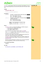
 sets all digital outputs of the specified module HSM-24V on the LS

bus to the level High oder Low and returns the status of all channels as bit pat-
tern.

Syntax

#INCLUDE ADWL16.INC

ret_val = LS_DIG_IO

(

pattern

)

Parameters

Notes

LS_DIG_IO

 only runs correctly, if the following conditions are given:

• There is only one module on the LS bus.
• The module is of type HSM-24V.
• The module's address is set to 1.

The channels are set as inputs or outputs using 

LS_DIGPROG

.

The 

pattern

 is applied to those channels only, which are set as out-

puts. Bits for input channels are ignored.

The return value contains the real state of both inputs and outputs. The
inputs have a filter causing about 12µs signal delay.

LS_DIG_IO

 resets the watchdog counter of the module to the start val-

ue. The counter remains enabled. The start value is set using 

LS_

WATCHDOG_INIT

.

Reset the active watchdog timer at least once to the start value within
the counting interval, in order to keep the module working.

To be used for the modules

HSM-24V

See also

LS_DIO_INIT

LS_DIGPROG

LS_WATCHDOG_INIT

pattern

Bit pattern, setting the digital outputs (see table).
Bit = 0: Set outputs to level Low.
Bit = 1: Set outputs to level High.

ret_val

Bit pattern representing the real state of all digital
channels (see table).
Bit = 0: Channel has level Low.
Bit = 1: Channel has level High.

Bit No.

31

30

29

2

1

0

Input  no.

32

31

30

3

2

1

LONG

LONG

Содержание ADwin HSM-24V

Страница 1: ...ADwin HSM 24V Module for LS Bus Manual ADwin LS Bus Manual version 1 0 September 2006...

Страница 2: ...eptember 2006 J ger Computergesteuerte Messtechnik GmbH Rheinstra e 2 4 D 64653 Lorsch Germany For any questions please don t hesitate to contact us Hotline 49 6251 96320 Fax 49 6251 5 68 19 E Mail in...

Страница 3: ...LS Bus Manual version 1 0 September 2006 III ADwin Table of Contents Typographical Conventions IV 1 Information about this Manual 1 2 The LS bus 2 3 HSM 24V 4 3 1 Hardware 4 3 2 Software 5 3 2 1 LS B...

Страница 4: ...ers to further information in this documentation or to other sources such as manuals data sheets literature etc C ADwin File names and paths are placed in angle brackets and characterized in the font...

Страница 5: ...cation experience and training as well as their knowledge of applicable technical standards guidelines accident prevention regulations and operating conditions have been authorized by a quality assura...

Страница 6: ...No data traffic Bus Termination The bus termination on the last module of the LS bus must be activated with the DIP switches Term deactivated on all other modules To activate the bus termination both...

Страница 7: ...is connected to the top hat rail which serves as protection earth PE Protection earth is connected to the screw PE on the module s top Module address Setting of DIP switches 1 2 3 4 0 0 0 0 0 Module d...

Страница 8: ...w level For each channel there is a LED indicating the status LED on relates to High level The channels have a permissible operation current of 0mA 150mA If the current exceeds 500mA at a channel the...

Страница 9: ...ed on the following pages or in the online help Input LS bus male Output LS bus female 1 2 3 4 5 6 7 8 9 SIGNAL HIGH RESERVED SIGNAL GND SIGNAL LOW RESERVED RESERVED RESERVED 5 4 3 2 1 9 8 7 6 SIGNAL...

Страница 10: ...HSM 24V ADwin 6 ADwin LS Bus Manual version 1 0 September 2006...

Страница 11: ...interval in order to keep the module working To reset the module use any module specific instruction or LS_WATCHDOG_RESET The watchdog function is used as to monitor the connection between ADwin syst...

Страница 12: ...ADWL16 inc init PROCESSDELAY 4000000 10Hz HP PAR_1 LS_DIO_INIT 1 PAR_2 LS_DIGPROG 1 0Fh channels 1 32 as output PAR_3 LS_WATCHDOG_INIT 1 1 1100 watchdog time 1 1 sec event REM set one channel to high...

Страница 13: ...n several channels at the same time Irrespective of this an over current of mor than 500mA automati cally switches off the concerned channel The channels of the module HSM 24V may only be operated in...

Страница 14: ...WL16 inc init PROCESSDELAY 4000000 10Hz HP PAR_1 LS_DIO_INIT 1 PAR_2 LS_DIGPROG 1 0Fh channels 1 32 as output PAR_3 LS_WATCHDOG_INIT 1 1 1100 watchdog time 1 1 sec event REM set one channel to high ro...

Страница 15: ..._INIT LS_WATCHDOG_INIT LS_DIG_IO ls module Specified module address on the LS bus 1 15 pattern Bit pattern setting the channels as inputs or out puts Bit 0 Set channels as inputs Bit 1 Set channels as...

Страница 16: ...WL16 inc init PROCESSDELAY 4000000 10Hz HP PAR_1 LS_DIO_INIT 1 PAR_2 LS_DIGPROG 1 0Fh channels 1 32 as output PAR_3 LS_WATCHDOG_INIT 1 1 1100 watchdog time 1 1 sec event REM set one channel to high ro...

Страница 17: ...nput channels are ignored The return value contains the real state of both inputs and outputs The inputs have a filter causing about 12 s signal delay LS_DIG_IO resets the watchdog counter of the modu...

Страница 18: ...L16 inc init PROCESSDELAY 4000000 10Hz HP PAR_1 LS_DIO_INIT 1 PAR_2 LS_DIGPROG 1 0Fh channels 1 32 as output PAR_3 LS_WATCHDOG_INIT 1 1 1100 watchdog time 1 1 sec event REM set one channel to high rot...

Отзывы: