background image

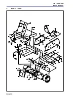
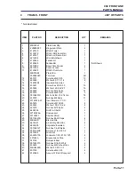
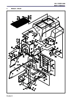
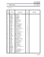
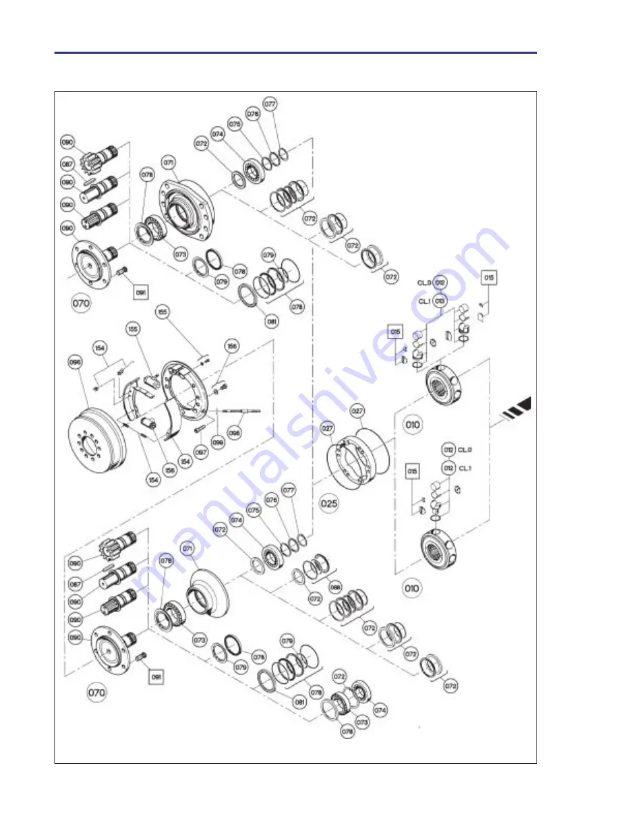
Parts-20

960 FRONTLINE

PARTS MANUAL

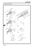
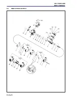
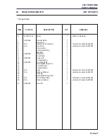
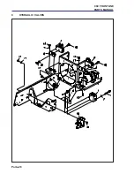
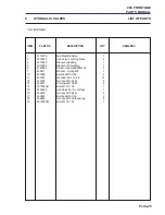
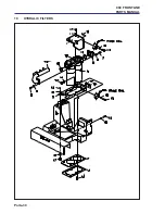
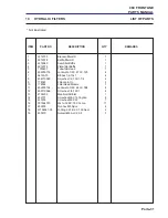
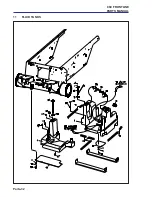
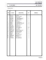
7A WHEEL MOTOR - FRONT

Содержание ransomes frontline 930

Страница 1: ...entretien doivent être formés et conscients des dangers encourus Ils doivent lire avec attention le manuel avant d essayer de monter d utiliser de régler ou maintenir la machine WARNING If incorrectly used this machine can cause severe injury Those who use and maintain this machine should be trained in its proper use warned of its dangers and should read the entire manual before attempting to set ...

Страница 2: ... 2002 Ransomes Jacobsen Limited All Rights Reserved ...

Страница 3: ...FORMANCE AREA 8 4 8 TORQUES 8 5 LUBRICATION AND MAINTENANCE LUBRICATION AND MAINTENANCE CHARTS 9 10 5 1 ENGINE FIRST 50 WORKING HOURS AND EVERY 250 WORKING HOURS 11 5 2 MACHINE LUBRICATE THE FOLLOWING POINTS WITH SHELL DARINA R2 GREASE WEEKLY EVERY 40 WORKING HOURS 11 5 3 MACHINE EVERY 400 WORKING HOURS 12 5 4 HYDRAULIC TEST PORTS 13 5 5 ENGINE MAINTENANCE EVERY 250 HRS 14 5 6 ENGINE MAINTENANCE E...

Страница 4: ... 6 2 r e t l i F l e u F e n i g n E 6 0 8 6 2 1 4 p m u P l e u F c i r t c e l E 4 4 0 3 2 1 4 t n e m e l E r e n a e l C r i A 2 8 1 1 0 0 5 r e t l i F l e u F e n i l n I 0 2 6 9 8 0 8 0 0 e g r a h C r e t l i F c i l u a r d y H l a i r e t a M t r o p p u S e c i v r e S o N t r a P n o i t p i r c s e D o N t r a P n o i t p i r c s e D l a u n a M s t r a P e n i g n E G 8 9 5 4 2 e c n...

Страница 5: ...61990 Wheel Tyre 2 Front 4301 8 008170780 Tyre 2 It may not be possible to illustrate every item With certain items purchased from outside suppliers some component parts may not be available from Ransomes and may need to be specially ordered from the supplier QUANTITIES Quantities shown are for one assembly or sub assembly USING THE PARTS LIST Determine the function and application of the part req...

Страница 6: ...erve the Highway Code both on and off the roads Keep alert and aware at all times Watch out for traffic when crossing or near roadways Stop the blades rotating before crossing surfaces other than grass Remember that some people are deaf or blind and that children and animals can be unpredictable Keep travelling speeds low enough for an emergency stop to be effective and safe at all times in any co...

Страница 7: ... not to get hands and feet trapped when rotating cylinders Make sure that other people are not touching any cutting units as rotation of one cylinder can cause the others to rotate To reduce the fire hazard keep the engine silencer and battery compartments free of grass leaves or excessive grease Replace worn or damaged parts for safety When working underneath lifted parts or machines make sure ad...

Страница 8: ...ge It may also be used to alert against unsafe practices IMPORTANT Transport speed is for highway use only Never select transport speed on grass areas or uneven or unsurfaced roads or tracks The operating instruction for the Cutting Units are contained in a separate Publication CaliforniaProposition65 Engine Exhaust some of its constituents and certain vehicle components contain or emit chemicals ...

Страница 9: ...8 8 litres 4 14 Imp galls 5 US galls Battery Exide 065 4 3 DIMENSIONS Width of cut 9 8 Model 2 95metres 116in 10 7 Model 3 23metres 127in Overallwidth metres in Overallwidth 1 55 metres 61in transport Overallheight 1 35 metres 53in Overalllength 3 1 metres 122in Overallweightof machine 9 8 Model 1554 kg 3426 lb 10 7 Model 1577 kg 3476lb 4 4 VIBRATIONLEVEL The machine was tested for whole body and ...

Страница 10: ...f b l 4 1 4 3 2 9 9 9 6 2 1 2 5 1 6 1 5 7 9 8 1 4 0 2 8 5 2 3 1 3 8 3 3 2 1 5 3 3 1 6 3 8 5 4 5 5 5 6 1 7 7 9 1 5 3 5 8 7 5 2 3 7 7 8 8 2 1 1 0 3 6 1 8 8 8 2 1 1 5 3 1 6 1 9 3 3 4 7 1 1 7 2 1 1 6 1 5 9 1 8 5 8 9 5 2 6 1 5 7 1 2 2 2 9 6 2 4 3 6 0 1 8 8 2 0 1 3 4 9 3 7 7 4 8 7 1 7 1 4 6 4 0 0 5 5 3 6 9 6 7 1 6 5 2 5 9 6 9 4 7 0 5 9 2 5 1 1 8 1 1 3 6 3 4 8 9 2 6 0 1 7 4 3 1 2 3 6 1 4 1 1 1 1 5 7 8 3 ...

Страница 11: ... r e t l i F l e u F e c a l p e R z z E N I H C A M m e t s y S k c o l r e t n I k c e h C z l e v e L t n a l o o C p u p o T k c e h C z e r u s s e r P e r y T k c e h C z d i u l F c i l u a r d y H p u p o T k c e h C z m o r f s s a r G e v o m e R n a e l C k c e h C p m u P t n e m t r a p m o C e n i g n E r o t a i d a R n e e r c S g u B t n e m t r a p n o C z s s e n t h g i T r o F...

Страница 12: ... Q E P Y T L I O E N I G N E r e t l i f h t i w s e r t i L 6 0 1 G S F S E S 0 3 W 0 1 L I O C I L U A R D Y H r e t l i f h t i w s e r t i L 0 7 3 6 4 s u l l e T l l e h S R O T A I D A R T N A L O O C s e r t i L 5 5 E Z E E R F I T N A 0 5 z z z z z Lubricate every 40 working hours at arrows 5 LUBRICATION AND MAINTENANCE ...

Страница 13: ... C Oil fill Change Engine Oil Filter A a Removesingle unitcartridge A b Clean area on crankcase c Apply thin coat of oil to cartridge gasket beforeinstalling d Tighten filter by hand only e Check for oil leaks around the cartridge gasket after engine is started Fig 1 5 2 MACHINE Lubricate the following points Weekly or every 40 working hours 1 Lubricate the following with Shell Darina R2 grease Fi...

Страница 14: ...on in either red zone as insufficient oil could damage hydraulic components Too much oil could lead to oil overflowing the reservoir as it heats up 7 Reinstall plug K 8 Start the tractor and allow to run at 1 4 throttle for approximately 5 minutes 9 Allow oil to cool and recheck the oil level and adjust as required Hydraulic oil type requirements Shell Tellus 46 ChangeHydraulicOilFilter CHARGE Fig...

Страница 15: ...lic oil at normal working temperature TEST PORTS Fig 7 8 9 1 Front Cutter Deck Pressure 220 bar 3200psi A Fig 7 Lift Pressure 63 5 bar 920 psi B Fig 7 2 RH LH Cutter Deck Pressure 210 bar 3045 psi A Fig 8 9 3 FWD Transmission Pressure 250 bar 3625psi A Fig 10 4 REV Transmission Pressure 210 bar 3045 psi B Fig 10 5 Charge Pressure 15 8 19 3 bar 230 280 psi Either A or B Fig 10 NOTE Any servicing of...

Страница 16: ...n Changing fuel filter Fig 10 1 Unscrew filter screw A from filter head 2 Bleed air from system as described in section 5 5 Bleeding air from fuel system 1 Turn the ignition switch to the ON position dont start engine 2 Open air vent A onto top of fuel filter to allow air to escape Fig 10 3 Retightenairvent 4 Open air vent A on side of injector pump to allow air to escape Fig 11 5 Retightenairvent...

Страница 17: ...s maintenancerecommendations If a label becomes worn or removed see the LABELS section of this manual or the tractor Parts Manual for replacement information NOTE When washing machine with pressure spray washers or steam cleaners avoid washing bearing areas because cleaning solutions might penetrate Wear eye protection when servicing battery WARNING Battery posts terminals and related accessories ...

Страница 18: ... thin film of oil to the seals of the new filters and install 6 Remove plug K and add the recommended oil Fig 5 until the indicator on the oil level gauge J is centered in the green area of the gauge Avoid operation in either red zone as insufficient oil could damage hydraulic components Too much oil could lead to oil overflowing the reservoir as it heats up 7 Reinstall plug K 8 Start the tractor ...

Страница 19: ... the rear 6 3 ALTERNATOR The fan belt is adjusted so that it can be deflected 5mm 0 2in with a force of 5 kg 11 lbs applied midway between the crankshaft and alternator pulley Fig 17 To adjust 1 Loosen alternator bolts A 2 Move the alternator to tighten or loosen fan belt 3 Tighten bolts A Check belt tension and condition of belt every 250 hours 6 1 SPEEDLIMITER The transport and mow speeds are fa...

Страница 20: ... as follows 2 Loosen locking nut on adjustment bolt E 3 Loosen 4 bolts G fastening the motor mounting plate to the cutter deck 3 visible in photo 4 Turn adjustment bolt E until proper tension is obtained 5 Retighten 4 bolts G and lock nut on adjust ment bolt E WINGDECKS 1 Adjust belt tension to 3 8 10 mm deflection at 10 lbs 5 kg force at the middle of the long rear span H If necessary adjust as f...

Страница 21: ... the blades with the tractor turned off and the decks securely supported Do not overheat or weaken the blades If blade becomes cracked or bent replace with a new blade to ensure safe operation f lift portion of blade is worn thin replace with a new blade to ensure safe operation Place block of wood W between blade and deck baffletopreventbladefromturningduring removal Keep hands clear of rotating ...

Страница 22: ...e v O e n i g n E w o l l e v e l t n a l o o C 1 f i n o i t u l o s e z e e r f i t n a 0 5 0 5 d d a d n a t c e p s n I 1 d e r i u q e r d e t c i r t s e r e k a t n i r i a r o t a i d a R 2 r o t a i d a r t a d r a u g h s e m e r i w n a e l C 2 r o t l e b r o t a n r e t l a p m u p r e t a W 3 n e k o r b r o e s o o l t l e b n a f t l e b n a f d n a t l e b r o t a n r e t l a p m ...

Страница 23: ...F Wheel Motor 6 LR Wheel Motor 7 RR Wheel Motor 8 Brake Valve 9 Aux Brake Valve 10 Oil Cooler 11 Filter Head 12 Reservoir Tank 13 Steer Valve 14 Steer Ram 15 Lift Valve 16 RH Lift Cylinder 17 Centre Lift Cyl s 18 LH Lift Cylinder 19 Front Cutter Deck Valve 20 Charge Filter 21 Front Cutter Deck Motor 22 Wing Deck Valves 23 LH Cutter Motor 24 RH Cutter Motor 25 Inlet Manifold ...

Страница 24: ...11 Battery Lamp 12 Oil Temperature Lamp 13 Oil Pressure Lamp 14 Cutting Deck Switch Lamp 15 Cutting Deck Switch 16 Fuel Guage 17 Temperature Guage 18 Beacon Switch Optional 19 Hazard Swicth 20 Lights 21 Direction Indicators 9 2 ELECTRICALCIRCUITINSTRUMENT 9 SCHEMATICS CABLECOLOURCODE R Red G Green O Orange S Grey B Black W White K Pink P Violet Y Yellow U Blue N Brown LG Light Green E G R W Red Wh...

Страница 25: ...c Oil Tempature 41 Fuel Level Sender 42 Water Temperture Sender 43 Engine Oil Pressure Switch 44 Horn Relay 45 Horn 46 Start Reley 47 Alarm Relay 48 Seat Switch 49 Park Switch 50 Diff Lock Switch 51 FuelPump 52 Starter 53 Battery 56 Centre Relay 57 LH Deck Relay 58 Deck enable Switch 59 Diff Lock Valve 60 4WD Relay 61 RH Deck Relay 62 Centre Deck Switch 63 LH Deck Kill Switch 64 RH Deck Kill Switc...

Страница 26: ...FUSES The secondary fuse panel is situated under the front towercover FUSE BLOCK 1 Fuse A 10Amp Fuel pump Alternator Fuse B 20Amp Main Ignition Fuse C 10Amp Horn Fuse D 10Amp Glow Plug Relay Fuse E 10Amp Beacon Fuse F Spare FUSE BLOCK 2 Fuse A 20Amp Accessory Fuse B 20Amp Air Seat Fuse C 20Amp Heated Jacket Fuse D Spare Fuse E Spare Fuse F Spare FUSE BLOCK 3 Fuse A 10Amp LH Headlamp Fuse B 10Amp R...

Страница 27: ...Relays are situated under the front tower cover Relay A Flasher Relay Relay B RH Deck Relay Relay C Centre Deck Relay Relay D LH Deck Relay Relay E 4 Wheel Drive Relay Relay F Start Relay Relay G Horn Relay Relay H Alarm Relay Relay I Accessory Relay Relay J Accessory Control Relay Relay K Seat Delay Relay ...

Страница 28: ...GB 26 GB FRONTLINE 960 Series LQ MAINTENANCE AND PARTS MANUAL NOTES ...

Страница 29: ...E 8 4 8 COUPLES DE SERRAGE 8 5 GRAISSAGE ET MAINTENANCE TABLEAU DE MAINTENANCE ET DE GRAISSAGE 9 10 5 1 MOTEUR 50 PREMIERES HEURES D HORAMETRE PUIS TOUTES LES 250 HEURES D HORAMETRE 11 5 2 MACHINE GRAISSAGE DES COMPOSANTS SUIVANTS HEBDOMADAIREMENT OU TOUTES LES 40 HEURES D HORAMETRE 11 5 3 MACHINE TOUTES LES 400 HEURES D HORAMETRE 12 5 4 ORIFICES D ESSAIS HYDRAULIQUES 13 5 5 MAINTENANCE DU MOTEUR ...

Страница 30: ...F 6 0 8 6 2 1 4 t n a r u b r a c à e u q i r t c e l é e p m o P 4 4 0 3 2 1 4 r i a d r u e t a r u p é d t n e m é l E 2 8 1 1 0 0 5 e n g i l n e t n a r u b r a c à e r t l i F 0 2 6 9 8 0 8 0 0 e u q i l u a r d y h e r t l i F e g r a h C i u p p a d s t n e m u c o D e c è i P o N n o i t p i r c s e D e c è i P o N n o i t p i r c s e D s e d e r u t a l c n e m o N e g n a h c e r e d s ...

Страница 31: ...161990 Roue moyeu 2 Avant 4301 8 008170780 Pneu 2 Il se peut que l illustration de tous les articles ne soit pas possible Pour certains articles achetés à des fournisseurs externes il se peut que des composants ne soient pas disponibles chez Ransomes et que ceux ci doivent être commandés spécialement auprès du fournisseur QUANTITES Les quantités indiquées s appliquent à un ensemble ou sous ensembl...

Страница 32: ... du Code de la Route aussi bien sur les routes qu en dehors Soyez toujours vigilant Arrêtez la rotation des lames avant de traverserdessurfacesnonherbues Rappelez vous que certaines personnes sont sourdes on aveugles et que les enfants et animaux sont impredicables Faites très attention aux passants Ne roulez jamais trop vite pour qu un arrêt d urgence reste toujours possible Avant de tondre enlev...

Страница 33: ...uler sur le moteur le silencieux ou la batterie Pour des raisons de sécurité remplacez les pièces usées ou endommagées Quand il faut travailler sous des composants ou machine levés veillez à utiliser un support stable Ne démontez pas la machine sans avoir auparavant fait chuter les tensions résiduelles qui risquent d activer les pièces Ne modifiez pas la vitesse du moteur au delà de la vitesse max...

Страница 34: ...nt à vous informer que les fumées moteur de cette machine ou de certains de ses composants renferment des produits chimiques susceptibles de provoquer des cancers déformités natales et séquelles AVERTISSEMENT Les batteries produisent des gas explosifs renferment de l acide corrosif et génèrent un courant électrique assez élevé risquant de causer des brûlures AVERTISSEMENT Lors de l entretien de la...

Страница 35: ... d huile 10 6 litres Carburant Diesel No 2 D ASTM D975 4 2 SPECIFICATIONSDELAMACHINE Structure du châssis Châssis en acier formé rails de caisse poutre Entraînementde l unité de coupe Les moteurs hydrauliques à cylindrée constante couplés aux unités de coupe offrent une courroied entraînementdirecte Transmission 4 roues motrices permanentes Pompeàcylindréevariable couplée à 280 cc aux moteurs des ...

Страница 36: ...7 3 0 5 7 5 5 0 1 6 6 2 1 4 2 4 5 3 2 7 4 4 4 9 7 2 3 1 3 9 5 1 7 2 4 1 5 6 8 6 1 7 3 1 8 2 9 1 4 1 3 2 0 3 5 1 7 4 5 9 8 0 9 1 3 8 6 2 9 1 2 3 3 3 4 6 9 6 8 2 1 2 7 5 2 6 1 6 3 0 4 3 4 6 3 6 9 1 1 4 9 5 1 9 8 1 3 4 8 4 4 1 8 3 5 S D A E R H T C N U n i a i D E D A R G A E D A R G S E D A R G T E D A R G V E D A R G X t f f b l t f f b l t f f b l t f f b l t f f b l 4 1 4 3 2 9 9 9 6 2 1 2 5 1 6 ...

Страница 37: ...v r e t n i d t i u c r i c e l r e i f i r é V z r u e s s i d i o r f e r u d u a e v i n e l r i l b a t é R r e i f i r é V z s u e n p s e d n o i s s e r p a l r e i f i r é V z e u q i l u a r d y h e d i u l f e l r i l b a t é r r e i f i r é V z r u e t o m t n e m i t r a p m o c e l r i n e t e r t n e r e i f i r é V t e s e t c e s n i à e r t l i f e p m o p a l e d t n e m e g o l ...

Страница 38: ...amètre 5 GRAISSAGE ET MAINTENANCE S E D N A M M O C E R S E D I U L F E T I T N A U Q E P Y T R U E T O M E L I U H n o i t a r t l i f c e v a s e r t i l 6 0 1 G S F S E S 0 3 W 0 1 E L I U H E U Q I L U A R D Y H n o i t a r t l i f c e v a s e r t i l 0 7 3 6 4 s u l l e T l l e h S R U E S S I D I O R F E R R U E T A I D A R E D s e r t i l 5 5 L E G I T N A 0 5 ...

Страница 39: ...ur A a Retirez la cartouche A b Nettoyez la surface du carter moteur c Appliquez une fine couche d huile sur le joint de la cartouche avant de l installer d Serrez le filtre à la main e Vérifiez l absence de fuites d huile autour du joint de la cartouche après le démarrage du moteur Schéma 1 5 2 MACHINE Graissagedescomposants suivants Hebdomadairement ou toutes les 40 heures d horamètre 1 Utilisez...

Страница 40: ...u se situe dans la partie rouge car une insuffisance d huilehydrauliquerisqued endommagerles composants hydrauliques Un excès d huile peutentraînerundébordementduréservoirau momentduchauffage 7 Reposez le bouchon K 8 Démarrez la machine et laissez la tourner 5 minutes environ à 1 4 de son régime 9 Laissez l huile se refroidir puis vérifiez de nouveau son niveau et rétablissez le le cas échéant Typ...

Страница 41: ...urenormalede service ORIFICES D ESSAIS Schéma 7 8 9 1 Pression du plateau de coupe avant 220 bars A Schéma 7 Pression de levage 63 5 bars B Schéma 7 2 Pression des plateaux de coupe droit et gauche 210 bars A Schémas 8 9 3 Pression de transmission Marche avant 250 bars A Schéma 10 4 Pression de transmission Marche arrière 210 bars B Schéma 10 5 Pression de charge 15 8 19 3 bars A ou B Schéma 10 RE...

Страница 42: ...arburant Schéma 10 1 Dévissez le filtre A de la tête du filtre 2 Purgez l air du circuit comme l explique la section 5 5 Purge d air du circuit carburant 1 Placez le contact sur MARCHE ne démarrez pas le moteur 2 Ouvrez la mise à l air libre A au dessus du filtre à carburant pour laisser l air s échapper Schéma11 3 Resserrez la mise à l air libre 4 Ouvrez la mise à l air libre C située sur le côté...

Страница 43: ...et boulons La pression des pneus doit toujours être de 1 kg cm2 Respectez les consignes de maintenance provenantduconstructeurdumoteur Quand un autocollant est usé ou manque reportez vousauchapitreintitulé VIGNETTES du présent manuel ou de la nomenclature des pièces de rechange pour ce qui concerne leur remplacement REMARQUE Si vous lavez la machine avec un jet d eau sous pression ou jet de vapeur...

Страница 44: ...ge 7 Reposez le bouchon K 8 Démarrez la machine et laissez la tourner 5 minutes environ à 1 4 de son régime 9 Laissez l huile se refroidir puis vérifiez de nouveau son niveau et rétablissez le le cas échéant Type d huile hydraulique à utiliser Shell Tellus 46 Remplacement du filtre à huile hydraulique Schéma 6 Réf à P 12 1 Essuyez la boîte métallique et le logement du filtre pour éliminer les sale...

Страница 45: ...contre écrous N des joints à rotule près des deux roues arrière 2 Faites tourner le pivot d essieu O jusqu à ce que les roues s alignent correctement Ajustez les deux pivots d essieux de la même manière 3 Resserrez les contre écrous Les pneus avant doivent s être rapprochés de 1 8 par rapport aux pneusarrière 6 3 ALTERNATEUR La courroie de ventilateur est réglée de façon à avoir une déflexion de 5...

Страница 46: ...écrou de la vis de réglage E 3 Desserrez les quatre 4 boulons G maintenant la plaque de montage du moteur au plateau de coupe 3 boulons sont illustrés 4 Faites tourner la vis de réglage E jusqu à ce que la tension soit correcte 5 Resserrez les quatre 4 boulons G et le contre écrou de la vis de réglage E PLATEAUXLATERAUX 1 Ajustez la tension de la courroie de façon à obtenir une déflexion de 10 mm ...

Страница 47: ...ffectuertoute intervention sur les lames Ne surchauffez pas et n affaiblissez pas les lames Quand une lame est déformée ou fissurée remplacez laafind assurerunfonctionnement en toute sécurité Quand une section de levage de lame est amincie par l usure remplacez la afin d assurer un fonctionnement en toute sécurité Placez une cale en bois W entre la lame et la chicane du plateau pour que la lame ne...

Страница 48: ... e d s e t i u d n o c é t i r u c é s e d s e g a l l i u o r r e V 2 e l r e t t i u q e d t n a v a e c a l p n e n o n r u e t a r é p o e g è i s e d t n a v a t ê r r a l à e t n o t e d r u e t p u r r e t n i l e r t t e M 2 e g è i s e l r e t t i u q u d e f f u a h c r u S r u e t o m e d e d i u q i l u d u a e v i n s a B 1 t n e m e s s i d i o r f e r 0 5 0 5 l e g i t n a n o i t u...

Страница 49: ...roue arrière droit 8 Soupape de frein 9 Soupape de frein auxiliaire 10 Refroidisseur d huile 11 Tête de filtre 12 Réservoir carter 13 Soupape de direction 14 Vérin de direction 15 Soupape de levage 16 Vérin de levage droit 17 Vérins de levage centraux 18 Vérin de levage gauche 19 Soupape de plateau de coupe avant 20 Filtre de charge 21 Moteur de plateau de coupe avant 22 Soupapes des plateaux laté...

Страница 50: ...batterie 12 Témoin lumineux de température d huile 13 Témoin lumineux de pression d huile 14 Témoin lumineux d interrupteur de plateau de coupe 15 Interrupteur de plateau de coupe 16 Jauge de carburant 17 Jauge de température 18 Interrupteur de gyrophare Option 19 Interrupteur des feux de danger 20 Feux 21 Clignotants 9 2 COMPOSANTSDUCIRCUITELECTRIQUE 9 SCHEMATIQUE CODECOULEURDESCABLES R Rouge G V...

Страница 51: ...de coupure du plateau droit 65 Soupape du plateau de coupe droit 66 Soupape du plateau de coupe gauche 67 Soupape du plateau de coupe central 68 Module de temporisation de siège 69 Coupure du moteur de desserrage de frein 70 Electro aimant de carburant moteur 71 Division de gyrophare 72 Alimentation d accessoire 73 Alimentation de siège pneumatique 74 Alimentation de chemise chauffée 75 Distribute...

Страница 52: ... trouve sous le couvercle avant de la colonne de direction BLOC DE FUSIBLES 1 Fusible A 10 A Pompe carburant alternateur Fusible B 20 A Allumage principal Fusible C 10 A Klaxon Fusible D 10 A Relais de bougie de préchauffage Fusible E 10 A Gyrophare Fusible F de rechange BLOC DE FUSIBLES 2 Fusible A 20 A Accessoire Fusible B 20 A Siège pneumatique Fusible C 20 A Chemise chauffée Fusible D de recha...

Страница 53: ...DES RELAIS Les relais se trouvent sous le couvercle avant de la colonne de direction Relais A Clignotant Relais B Plateau droit Relais C Plateau central Relais D Plateau gauche Relais E 4 roues motrices Relais F Démarrage Relais G Klaxon Relais H Alarme Relais I Accessoire Relais J Commande d accessoire Relais K Temporisation de siège ...

Страница 54: ...F 26 F FRONTLINE 960 Série LQ MANUEL DE MAINTENANCE ET NOMENCLATURE DES PIECES DE RECHANGE REMARQUES ...

Страница 55: ...7 4 6 AANBEVOLENSMEERMIDDELEN 8 4 7 MAAIPRESTATIE GEBIED 8 4 8 DRAAIKOPPELS 8 5 SMEERING EN ONDERHOUD SMEER ENONDERHOUDSSCHEMA 9 10 5 1 MOTOR EERSTE 50 EN IEDERE 250 BEDRIJFSUREN 11 5 2 MACHINE SMEER DE VOLGENDE PUNTEN WEKELIJKS OF NA IEDERE 40 BEDRIJFSUREN 11 5 3 MACHINE IEDERE 400 BEDRIJFSUREN 12 5 4 HYDRAULISCHE DRUKCONTROLEFACILITEIT 13 5 5 MOTORONDERHOUD IEDERE 250 BEDRIJFSUREN 14 5 6 MOTORON...

Страница 56: ...s d n a r b r o t o M 6 0 8 6 2 1 4 e h c s i r t c e l E p m o p f o t s d n a r b 4 4 0 3 2 1 4 t n e m e l e r e t l i f t h c u L 2 8 1 1 0 0 5 r e t l i f f o t s d n a r b n j i l n i 0 2 6 9 8 0 8 0 0 r e t l i f h c s i l u a r d y H d a a L l a a i r e t a m s g n i n u e t s r e d n o e c i v r e S r n k u t S g n i v j i r h c s e B r n k u t S g n i v j i r h c s e B g n i d i e l d n ...

Страница 57: ...7 008161990 Wiel en band 2 Voorkant 4301 8 008170780 Band 2 Het is niet altijd mogelijk om ieder onderdeel te illustreren Aangezien bepaalde onderdelen van externe leveranciers afkomstig zijn bestaat de kans dat ze niet door Ransomes kunnen worden geleverd maar speciaal bij de betrokken leverancier moeten worden besteld AANTALLEN De vermelde aantallen zijn voor één systeem of sub systeem GEBRUIKVA...

Страница 58: ... snijcilinders Defectedempersvervangen Uitsluitend maaien bij daglicht of als goed kunstlicht beschikbaar is Neemaltijddeverkeersvoorschrifteninacht zowel op openbare wegen als elders Blijf altijd alert In de buurt van wegen of gedurendehetoverstekenvanwegen altijd lettenopandereweggebruikers Voordatoverandereoppervlakkendangras wordt gereden de maaibladen altijd stilzetten Denk eraan dat sommige ...

Страница 59: ...ieenhedenaangeziendraaiingvaneenvan de cilinders hetzelfde bij de andere kan teweegbrengen 3 9 AFSTELLINGEN SMERINGEN ONDERHOUD Zet de motor stil en overtuig u ervan dat alle bewegendedelenstationairzijn Trek de handrem aan en ontkoppel alle aandrijvingen Lees alle toepasselijke onderhoudsvoorschriftenaandachtigdoor Gebruikuitsluitenddevervangingsonderdelen die door de oorspronkelijke fabrikant zi...

Страница 60: ... is opgenomenendebrandstofdampenzijn vervlogen Laat de motor eerst afkoelen voordat de machineoverdektwordtgestald Stal de machine nooit met brandstof in de tank in een ruimte waar de dampen een open vlamofvonkkunnenbereiken Als de brandstoftank moet worden afgetapt dient dit altijd in de openlucht te gebeuren Morsgeenbrandstofopheteonderdelen Tijdens het onderhoud van accu s MAG NIET WORDEN GEROO...

Страница 61: ...doliecarter 10 6 liter Brandstof Nr 2 D diesel ASTM D975 4 2 MACHINESPECIFICATIE Frameconstructie Profielstalen chassis voor zwaar gebruik metkokerframerails Aandrijving Hydraulische motors met vaste maaieenheden capaciteit rechtstreeks gekoppeldaanmaaieenheid Transmissie Permanentevierwielaandrijving Rechtstreeksgekoppelde regelbarehydropompnaar rechtstreeksgekoppelde voorwiel enachterwielmotors ...

Страница 62: ...2 9 6 2 4 3 6 0 1 8 8 2 0 1 3 4 9 3 7 7 4 8 7 1 7 1 4 6 4 0 0 5 5 3 6 9 6 7 1 6 5 2 5 9 6 9 4 7 0 5 9 2 5 1 1 8 1 1 3 6 3 4 8 9 2 6 0 1 7 4 3 1 2 3 6 1 4 1 1 1 1 5 7 8 3 1 7 9 4 1 9 9 8 1 0 0 3 2 8 3 1 0 7 6 0 2 8 1 3 6 9 1 0 9 4 2 7 1 0 3 2 1 1 9 8 8 4 1 4 2 5 0 6 2 3 0 3 3 2 0 0 4 S D A E R H T C I R T E M H C T I P E S R O C a i D m m E D A R G 6 4 E D A R G 8 4 E D A R G 8 8 E D A R G 9 0 1 E ...

Страница 63: ...l e s s i w r e v s r e t l i f f o t s d n a r B z z E N I H C A M n e r e l o r t n o c m e e t s y s l e d n e r g r e V z n e l l u v j i b n e r e l o r t n o c u a e v i n f o t s i e o l v l e o K z e l o r t n o c s g n i n n a p s n e d n a B z n e l l u v j i b n e r e l o r t n o c f o t s i e o l v e h c s i l u a r d y H z e t l e e d e g p m o p e t l e e d e g r o t o M r o t a i d ...

Страница 64: ...fsuren 5 SMEERING EN ONDERHOUD N E S I E F O T S I E O L V D I E H L E E V E O H E P Y T E I L O R O T O M r e t l i f t e m r e t i l 6 0 1 G S F S E S 0 3 W 0 1 E I L O K E I L U A R D Y H r e t l i f t e m r e t i l 0 7 3 6 4 s u l l e T l l e h S R U E T A I D A R F O T S I E O L V L E O K r e t i l 5 5 S E I R V I T N A 0 5 ...

Страница 65: ...roliefilter vervangen A a Verwijderdeenkelvoudigepatroon A b Reinighetbetreffendekrukkastgedeelte c Breng vóór installatie een dun laagje olie op de patroonpakking aan d Draaihetfilterhandvast e Controleer op olielekken rond de patroonpakking na het starten van de motor 5 2 MACHINE Smeer de volgende punten wekelijks of na iedere 40 bedrijfsuren 1 Smeer de volgende punten met Shell Darina R2 vet Af...

Страница 66: ...rking in beide rode gebieden omdatonvoldoendeoliedehydraulische onderdelen kan beschadigen Te veel olie kan leidentothetoverlopenvanhetreservoir wanneerdezeopwarmt 7 Plaats plug K weer terug 8 Start de tractor en laat deze ongeveer 5 minuten op een 1 4 ingedrukte gaspedaal lopen 9 Laat de olie koud worden en controleer het oliepeilweer Zonodigbijvullen Typevereiste hydraulische olie Shell Tellus 4...

Страница 67: ... kunnen controleren Tenzijanderszinsaangegevenmoetiederetest wordenuitgevoerdterwijldehydrauliekoliede normalebedrijfstemperatuurheeft TESTPOORTEN Afb 7 8 9 1 Voormaaidekdruk 220 bar A Afb 7 Hefdruk 63 5 bar B Afb 7 2 R L maaidekdruk 210 bar A Afb 8 9 3 VOORW Transmissiedruk 250 bar A Afb 10 4 ACHTERW Transmissiedruk 210bar B Afb 10 5 Vuldruk 15 8 19 3 bar A of B Afb 10 N B Alle servicing van het ...

Страница 68: ...vangen Afb 10 1 Draai het filter A los van de filterkop 2 Ontlucht het systeem zoals beschreven in sectie 5 5 Ontluchtingvanhetbrandstofsysteem 1 Draai de startschakelaar naar de AAN stand maar start de motor niet 2 OpendeventilatieklepAopbovenzijdevan brandstoffilter zodat de lucht kan ontsnappen Afb 10 3 Zetdeventilatieklepweervast 4 Open de ventilatieklep A aan zijkant van verstuiver zodat de l...

Страница 69: ...uten altijd stevig vastzitten Houd de bandendruk op 1 kg cm2 Volgdeaanbevolenonderhoudsproceduresvan demotorfabrikantop Als een sticker slijt of verloren gaat raadpleeg dan de STICKER sectie in deze handleiding of detractoronderdelenhandleidingvoorinformatie oververvanging N B Wanneer de machine wordt gewassen met een drukspuitwasserofstoomreiniger vermijddande gedeeltenwaarzichlagersbevinden aang...

Страница 70: ...ctor en laat deze ongeveer 5 minuten op een 1 4 ingedrukte gaspedaal lopen 9 Laat de olie koud worden en controleer het oliepeil weer Zonodigbijvullen Typevereiste hydraulische olie Shell Tellus 46 Hydrauliekoliefilter vervangen Afb 6 pagina 12 1 Veegeventueelaanwezigvuilvandefilterbusen het filterhuis 2 Plaats een geschikte druipbak onder het filter 3 Schroefdefilterhouderlos verwijderhet filtere...

Страница 71: ...werk 1 Maak de borgmoeren N los bij de kogelscharnierenvlakbijbeideachterwielen 2 Draai de trekstang O totdat de wielen in de juiste positie staan Stel de beide trekstangen gelijk in 3 Maak de borgmoeren weer vast De banden moeten 1 8 dichter bij de voorzijde staan dan bij deachterzijde 6 3 WISSELSTROOMDYNAMO Deventilatorriemisgoedgespannenwanneereen halverwege tussen de krukas en de dynamopoelie ...

Страница 72: ...e afstelbouten E 3 Maak de 4 bouten los G die de montageplaat van de motor op het maaidek bevestigen 3 zijn er zichtbaar op de foto 4 Draai de afstelbout E totdat de juiste spanning isverkregen 5 Maak de 4 bouten G en de borgmoer weer vast op de afstelbout E ZIJDEKKEN 1 Stel de bandspanning af op een afwijking van 10 mm bij een kracht van 5 kg in het midden van de langeachteroverspanningH Zonodiga...

Страница 73: ... onderhoud uit te voeren aan de bladen Debladennietoververhittenofverzwakken Vervangeengescheurdofgebogenbladmet een nieuw blad om een veilige werking te kunnengaranderen Vervangeenbladwaarvanhethefgedeelteis verleten met een nieuw blad om een veilige werkingtekunnengaranderen Plaats een houtblok W tussen het blad en de dekplaat zodat het blad niet kan draaien tijdens hetverwijderen Hou de handen ...

Страница 74: ...V 1 n e t h c u l t n o t e i n n e g n i l e d n e r g r e v s d i e h g i l i e V 2 g n i t t i z s r e d r u u t s e b e d t a d r o o v d l e t s e g n i n e t a l r e v t d r o w e d t a d g r o Z t i u r a a l e k a h c s i a a m e d t e Z 2 s i t e i n g n i l e d n e r g r e v t i u r e t h c a t i u r o o v e l a r t u e n t k u r d e g n i n a v g n i t t i h r e v r e v O r o t o m e d ...

Страница 75: ...or r voorwiel 5 Motor l voorwiel 6 Motor l achterwiel 7 Motor r achterwiel 8 Remklep 9 Remhulpklep 10 Oliekoeler 11 Filterkop 12 Reservoir Tank 13 Stuurklep 14 Stuurplunjer 15 Hefklep 16 R hefcilinder 17 M hefcilinders 18 L hefcilinder 19 Klep voormaaidek 20 Vulfilter 21 Motor voormaaidek 22 Kleppen zijdekken 23 Motor l maaieenheid 24 Motor r maaieenheid 25 Inlaatspruitstuk ...

Страница 76: ...mp 11 Acculamp 12 Olietemperatuurlamp 13 Oliedruklamp 14 Maaidekschakelaarlamp 15 Maaidekschakelaar 16 Brandstofmeter 17 Temperatuurmeter 18 Zwaailichtschakelaar Optioneel 19 Gevarenlichtschakelaar 20 Lampen 21 Richtingaanwijzers 9 2 ELEKTRISCHCIRCUITINSTRUMENTEN 9 SCHEMATISCH DIAGRAM KABELKLEURCODE R Rood G Groen O Oranje S Grijs B Zwart W Wit K Roze P Violet Y Geel U Blauw N Bruin LG Lichtgroen ...

Страница 77: ...aulische olietemperatuur 41 Brandstofpeilzender 42 Watertemperatuurzender 43 Motoroliedrukschakelaar 44 Claxonrelais 45 Claxon 46 Startmotorrelais 47 Alarmrelais 48 Zittingschakelaar 49 Parkeerremschakelaar 50 Diff vergrendelingschakelaar 51 Brandstofpomp 52 Startmotor 53 Accu 56 Middendekrelais 57 L dekrelais 58 Schakelaar dekwerking 59 Diff vergrendelklep 60 4WD relais 61 R dekrelais 62 Middende...

Страница 78: ...40 Amp Cabinezekering Relais D Gloeibougierelais SECUNDAIREZEKERINGEN De secundaire zekeringkast bevindt zich onder het voorladerdeksel ZEKERINGKAST1 Zekering B 20 Amp Hoofdontsteking Zekering D 10 Amp Gloeibougierelais ZEKERINGKAST2 Zekering A 20 Amp Accessoire Zekering B 20 Amp Luchtzitting Zekering C 20 Amp Verwarmde mantel ZEKERINGKAST3 Zekering A 10 Amp L koplamp Zekering B 10 Amp R koplamp Z...

Страница 79: ...ES Derelaisbevindenzichonderdevoorladerdeksel Relais A Flitslichtrelais Relais B R dekrelais Relais C M dekrelais Relais D L dekrelais Relais E 4WD relais Relais F Startmotorrelais Relais G Claxonrelais Relais H Alarmrelais Relais I Accessoirerelais Relais J Relais accessoirebediening Relais K Relais zittingvertraging ...

Страница 80: ...NL 26 NL FRONTLINE 960 Serie LQ ONDERHOUDS EN ONDERDELENHANDLEIDING OPMERKINGEN ...

Страница 81: ...LEISTUNG FLÄCHE 8 4 8 DREHMOMENTE 8 5 SCHMIERUNG UND WARTUNG SCHMIER UND WARTUNGSTABELLE 9 10 5 1 MOTOR NACH DEN ERSTEN 50 BETRIEBSSTUNDEN UND ANSCHLIEßEND ALLE 250 BETRIEBSSTUNDEN 11 5 2 MASCHINE DIE FOLGENDEN STELLEN SCHMIEREN WÖCHENTLICH ODER ALLE 40 BETRIEBSSTUNDEN 11 5 3 MASCHINE ALLE 400 BETRIEBSSTUNDEN 12 5 4 PRÜFANSCHLÜSSE FÜR DIE HYDRAULIK 13 5 5 MOTORWARTUNG ALLE 250 STUNDEN 14 5 6 MOTOR...

Страница 82: ...r k r o t o M 6 0 8 6 2 1 4 e p m u p f f o t s t f a r K e h c s i r t k e l E 4 4 0 3 2 1 4 r e t l i f t f u L 2 8 1 1 0 0 5 r e t l i f s g n u t i e l f f o t s t f a r K 0 2 6 9 8 0 8 0 0 r e t l i f k i l u a r d y H d n a t s u z e d a L l a i r e t a m s g n u z t u t s r e t n u s g n u t r a W r n l i e T g n u b i e r h c s e B r n l i e T g n u b i e r h c s e B h c u b d n a h l i e ...

Страница 83: ...1 6 002993010 Schmiervorrichtung 1 4301 7 008161990 Rad und Reifen 2 vorn 4301 8 008170780 Reifen 2 Es ist nicht immer möglich sämtliche Artikel abzubilden Da einige Teile von Fremdlieferanten angekauft werden sind sie nicht jederzeit von Ransomes erhältlich und müssen speziell vom Lieferanten bestellt werden MENGEN Angegebene Mengen gelten nur für eine Baugruppe oder Untergruppe ANWENDUNG DER TEI...

Страница 84: ...ageslichtoderausreichender künstlicherBeleuchtung BeachtenSiedieStraßenverkehrsordnungauch abseits der Straße Seien Sie jederzeit wachsam und konzentriert Achten Sie auf den Verkehr wenn Sie Straßen kreuzen oder neben ihnenfahren Schalten Sie die Schneidzylinder aus wenn Sie FlächenohneGrasbewuchspassieren Denken Sie daran daß manche Leute taub oder blind sind und daß Kinder und Tiere unberechenba...

Страница 85: ...ergelieferte Ersatzteileverwenden Sicherstellen daß keine anderen Personen irgendwelcheSchneidvorrichtungenberühren da ein Drehen eines Zylinders ein Rotieren der anderenZylinderverursachenkönnte ZumReduzierenderBrandgefahrmüssenMotor SchalldämpferundBatteriefächerfreivonGras Blättern oder übermäßiger Schmiere sein Verschlissene oder beschädigte Teile aus Sicherheitsgründenauswechseln Sicherstelle...

Страница 86: ... Chemikalien die dem Staat Kalifornien als krebserregend und Verursacher von Geburtsfehlern und anderen genetischen Gefahren bekannt sind ACHTUNG Batterien erzeugen zündfähige Gase und enthalten korrodierende Säuren sowie Stromstärken die hoch genug sind um Brandwunden zu verursachen ACHTUNG Unter Druck entweichendes Hydrauliköl kann in die Haut eindringen und eine ernsthafte Verletzung verursache...

Страница 87: ...R MASCHINE Rahmenkonstruktion Fahrgestellaus Hochleistungsformstahlmit Kastenrahmenschienen Antriebder Schneidvorrichtung Direkt an die Schneidvorrichtung angekoppeltehydraulische Konstantmotoren Getriebe konstanterVierradantrieb direktgekoppelte Verstellpumpeaufdirekt gekoppelte 280 cc Vorderrad 237ccHinterradmotoren Geschwindigkeiten Mähen 0 12 km h VORWÄRTS Fahren 0 22 km h VORWÄRTS Rückwärtsfa...

Страница 88: ... 2 2 9 6 2 4 3 6 0 1 8 8 2 0 1 3 4 9 3 7 7 4 8 7 1 7 1 4 6 4 0 0 5 5 3 6 9 6 7 1 6 5 2 5 9 6 9 4 7 0 5 9 2 5 1 1 8 1 1 3 6 3 4 8 9 2 6 0 1 7 4 3 1 2 3 6 1 4 1 1 1 1 5 7 8 3 1 7 9 4 1 9 9 8 1 0 0 3 2 8 3 1 0 7 6 0 2 8 1 3 6 9 1 0 9 4 2 7 1 0 3 2 1 1 9 8 8 4 1 4 2 5 0 6 2 3 0 3 3 2 0 0 4 S D A E R H T C I R T E M H C T I P E S R O C a i D m m E D A R G 6 4 E D A R G 8 4 E D A R G 8 8 E D A R G 9 0 1...

Страница 89: ...z z z z z E N I H C S A M n e f ü r p m e t s y s s g n u l e g e i r r e V n e l l ü f h c a n n e f ü r p d n a t s l e t t i m l h ü K z n e f ü r p k c u r d n e f i e R z n e l l ü f h c a n n e f ü r p t i e k g i s s ü l f k i l u a r d y H z m r i h c s r e l h e F m u a r n e p m u P m u a r r o t o M d n u n e g i n i e r n e f ü r p r e l h ü K d n u n e n r e f t n e s a r G s e d n e ...

Страница 90: ...HMIERUNG UND WARTUNG T I E K G I S S Ü L F E I D N A N E G N U R E D R O F N A E G N E M P Y T L Ö R O T O M r e t l i F t i m r e t i L 6 0 1 G S F S E S 0 3 W 0 1 r e t l i F t i m L Ö K I L U A R D Y H r e t i L 0 7 3 6 4 s u l l e T l l e h S T I E K G I S S Ü L F L H Ü K R E L H Ü K r e t i L 5 5 0 5 L E T T I M Z T U H C S T S O R F I T N A ...

Страница 91: ...ter wechseln A a Die aus einem Stück bestehende Patrone A entfernen b Den Bereich um das Kurbelgehäuse herumreinigen c Vor dem Einsetzen einen dünnen Ölfilm auf die Dichtung der Patrone geben d Den Filter nur mit der Hand festziehen e Nach dem Anlassen des Motors den Bereich um die Patronendichtung herum auf Öllecks prüfen 5 2 MASCHINE Die folgenden Stellen schmieren Wöchentlich oder alle 40 Betri...

Страница 92: ...Sie die Maschine möglichst nicht in einem der roten Bereiche da bei zu wenig Öl die HydraulikbauteileSchadennehmenkönnen Zu viel Öl könnte beim Erhitzen aus dem Tank austreten 7 Setzen Sie den Verschluss K wieder ein 8 Starten Sie den Traktor und lassen Sie ihn mit 1 4 des Gases ca 5 Minuten laufen 9 Lassen Sie das Öl abkühlen prüfen Sie erneut den Ölstand und füllen Sie bei Bedarf nach Geforderte...

Страница 93: ...n nicht anders angegeben muss das Hydrauliköl bei allen Tests die normale Betriebstemperaturhaben PRÜFANSCHLÜSSE Abb 7 8 9 1 DruckvordereSchneidevorrichtung 220 bar A Abb 7 Hubdruck 63 5 bar B Abb 7 2 Druck rechte und linke Schneidevorrichtung 210 bar A Abb 8 und9 3 DruckKraftübertragungvorwärts 250bar A Abb 10 4 DruckKraftübertragungrückwärts 210bar B Abb 10 5 Ladedruck 15 8 19 3 bar Entweder A o...

Страница 94: ... A vomFilterkopf abschrauben 2 Die Anlage wie in Abschnitt 5 5 beschriebenentlüften Kraftstoffanlageentlüften 1 Das Zündschloss auf die Stellung EIN drehen jedoch nicht den Motor anlassen 2 ÖffnenSiedieEntlüftungsvorrichtung A oben auf dem Kraftstofffilter damit die Luft austretenkann Abb 10 3 DieEntlüftungsöffnungwiederfestziehen 4 ÖffnenSiedieEntlüftungsvorrichtung A an der Seite der Einspritzpu...

Страница 95: ...er Neutral Sitzschalter etc überprüfen Prüfen dass sich die Schrauben und Muttern nicht gelockert haben Den Reifendruck auf 1 kg cm halten DenWartungsempfehlungendes Motorherstellersfolgen Sollte eines der Schilder unleserlich geworden sein oder fehlen können Sie Hinweise zum Ersatz im Kapitel ETIKETTEN des vorliegendenHandbuchesoderinTeilehandbuch desTraktorsnachschlagen HINWEIS Beim Waschen der ...

Страница 96: ...der ein 8 Starten Sie den Traktor und lassen Sie ihn mit 1 4 des Gases ca 5 Minuten laufen 9 Lassen Sie das Öl abkühlen prüfen Sie erneut den Ölstand und füllen Sie bei Bedarf nach GeforderteHydraulikölsorten Shell Tellus 46 Hydraulikölfilter Ladezustand wechseln Abb 6 Seite 12 1 Den Filterkanister und das Gehäuse abwischen umallevorhandenenVerschmutzungenzu beseitigen 2 UnterdemFiltereinegeeignet...

Страница 97: ... Nehmen Sie die Einstellung wie folgt vor 1 Lösen Sie die Sicherungsmuttern N an den Kugelgelenken in der Nähe der beiden Hinterräder 2 Drehen Sie die Spurstange O bis die Räder in der richtigen Stellung sind Stellen Sie beide Spurstangen um den gleichen Betrag nach 3 Ziehen Sie die Sicherungsmuttern wieder an Die Reifen sollten dann vorn 1 8 näher stehen als hinten 6 3 LICHTMASCHINE Der Keilrieme...

Страница 98: ...ockern Sie die 4 Schrauben G mit denen die MotorgrundplatteanderSchneidevorrichtung befestigt ist 3 auf dem Foto sichtbar 4 Drehen Sie die Stellscharaube E bis Sie die gewünschteSpannungerreichthaben 5 Ziehen Sie die 4 Schrauben G und die Sicherungsmutter an der Stellschraube E wieder fest FLÜGELVORRICHTUNG 1 Stellen Sie die Riemenspannung so ein dass der Riemen eine Auslenkung von 10 mm bei einer...

Страница 99: ...nd schwächen Sie die Messer nicht GesprungeneoderverbogeneMessersinddurch neue zu ersetzen um einen sicheren Betrieb zu gewährleisten Ist die Hubseite der Messer durch Verschleiß zu dünn geworden dann ersetzen Sie das Messer durch ein neues um einen sicheren Betrieb zu gewährleisten Stecken Sie einen Holzblock W zwischen das Messer und das Prallblech des Aulegers damit sich das Messer beim Ausbau ...

Страница 100: ... l e g e i r r e V n e f ü r P n e l l e t s S U A f u a r e t l a h c s h ä M n e D 2 s l a d e P s e d e r r e p s l a r t u e N e i d s s a d t s i t k c ü r d e g r e d e i n t h c i n s t r ä w k c ü R s t r ä w r o V ß i e h t f u ä l r o t o M r e D u z t s i d n a t s l l ü f l e t t i m l h ü K r e D 1 g i r d e i n 0 5 0 5 r e n i e t i m f r a d e B i e b d n u n e f ü r P 1 n e l l ü f...

Страница 101: ...inkes Hinterrad 7 Motor rechtes Hinterrad 8 Bremsventil 9 Zusatzbremsventil 10 Ölkühler 11 Filterkopf 12 Vorratsbehälter Tank 13 Lenkventil 14 Lenkkolben 15 Hubventil 16 Rechter Hubzylinder 17 Mittlere Hubzylinder 18 Linker Hubzylinder 19 Ventil vordere Schneidevorrichtung 20 Ladefilter 21 Motor vordere Schneidevorrichtung 22 Ventile Flügelvorrichtung 23 Linker Schneidemotor 24 Rechter Schneidemot...

Страница 102: ...rieanzeige 12 Leuchte Öltemperatur 13 Leuchte Öldruck 14 Leuchte Schalter Schneidevorrichtung 15 Schalter Schneidevorrichtung 16 Kraftstoffmesser 17 Temperaturmesser 18 Schalter Rundumleuchte Optional 19 Schalter Warnblinkanlage 20 Lampen 21 Blinker 9 2 ELEKTRISCHERSCHALTKREISDERANZEIGEELEMENTE 9 ANORDNUNGSPLAN FARBKODEDERKABEL R rot GN grün O orange GR grau S schwarz W weiß R rosa V violett GB ge...

Страница 103: ...eratur 43 Schalter Motoröldruck 44 Huprelais 45 Hupe 46 Starterrelais 47 Alarmrelais 48 Sitzschalter 49 Parkschalter 50 Schalter Differentialsperre 51 Kraftstoffpumpe 52 Anlasser 53 Batterie 56 RelaisMitte 57 Relais linke Vorrichtung 58 Schalter zur Aktivierung der Vorrichtung 59 Ventil Differentialsperre 60 Relais Vierradantrieb 61 Relais rechte Vorrichtung 62 Schalter mittlere Vorrichtung 63 Abs...

Страница 104: ...findetsichunterdervorderenMastabdeckung SICHERUNGSBLOCK1 Sicherung A 10 A Kraftstoffpumpe Lichtmaschine Sicherung B 20 A Hauptzündung Sicherung C 10 A Hupe Sicherung D 10 A Glühkerzenrelais Sicherung E 10 A Rundumleuchte Sicherung F unbelegt SICHERUNGSBLOCK2 Sicherung A 20 A Zubehör Sicherung B 20 A Luftsitz Sicherung C 20 A Geheizte Ummantelung Sicherung D unbelegt Sicherung E unbelegt Sicherung ...

Страница 105: ...erdervorderen Mastabdeckung Relais A Blinkrelais Relais B Relais rechte Vorrichtung Relais C Relais mittlere Vorrichtung Relais D Relais linke Vorrichtung Relais E Relais Vierradantrieb Relais F Starterrelais Relais G Relais Hupe Relais H Relais Alarm Relais I Relais Zubehör Relais J Relais Steuerung Zubehör RelaisK Sitzverzögerungsrelais ...

Страница 106: ...D 26 D FRONTLINE 960 Serie LQ WARTUNGSHANDBUCH UND ERSATZTEILLISTE HINWEISE ...

Страница 107: ...8 4 8 COPPIE 8 5 LUBRIFICAZIONE E MANUTENZIONE TABELLA DELLA LUBRIFICAZIONE E DELLA MANUTENZIONE 9 10 5 1 MOTORE DOPO LE PRIME 50 ORE ED OGNI 250 ORE DI LAVORO 11 5 2 MACCHINA LUBRIFICARE I SEGUENTI PUNTI SETTIMANALMENTE OPPURE OGNI 40 ORE DI LAVORO 11 5 3 MACCHINA OGNI 400 ORE DI LAVORO 12 5 4 APERTURE DI PROVA IDRAULICHE 13 5 5 MANUTENZIONE DEL MOTORE OGNI 250 ORE 14 5 6 MANUTENZIONE DEL MOTORE ...

Страница 108: ... r u b r a c o r t l i F e r o t o m 6 0 8 6 2 1 4 e t n a r u b r a c l e d a p m o P a c i r t t e l e 4 4 0 3 2 1 4 o r t l i f o t n e m e l E a i r a l l e d 2 8 1 1 0 0 5 a e n i l n i e t n a r u b r a c o r t l i F 0 2 6 9 8 0 8 0 0 o c i l u a r d i o r t l i F a c i r a C a z n e t s i s s a o t r o p p u s i d e l a i r e t a M e t r a p N e n o i z i r c s e D e t r a p N e n o i z i r...

Страница 109: ...010 Ingrassatore 1 4301 7 008161990 Ruota e pneumatico 2 Anteriore 4301 8 008170780 Pneumatico 2 In certi casi non è possibile illustrare ciascun articolo Con alcuni articoli acquistati presso fornitori esterni alcune parti componenti possono non essere disponibili presso la società Ransomes e in certi casi devono essere ordinate specialmente dal fornitore QUANTITÀ Le quantità illustrate sono per ...

Страница 110: ...Strada siasu strada che al di fuori di essa Prestare in tutti i casi il massimo livello d attenzione e prendere atto delle situazioni circostanti Prestare attenzione al traffico se si devono attraversare delle strade o si deve lavorare in prossimità di strade Interrompere la rotazione delle lame prima di attraversaresuperficinonerbose Considerare la possibile presenza di persone non vedenti e non ...

Страница 111: ... che tutte le parti mobili siano ferme Innestareifreniescollegaretutteletrasmissioni Leggere tutte le istruzioni pertinenti all assistenza Usaresololepartidiricambiooriginalifornitedal produttore Assicurarsi che altre persone non tocchino le partitaglienti perchélarotazionediuntamburo può far girare anche gli altri tamburi Per ridurre i rischi d incendio mantenere il motore ivanidelmotore delsilen...

Страница 112: ...el serbatoio all interno di un locale dove i vapori potrebbero venire a contatto con fiamme vive o scintille Se è necessario svuotare il serbatoio del combustibile farloall aperto Nondisperderedelcarburantesopracomponenti caldi NONFUMAREetenerelontanelefiammevive durante l assistenza tecnica alle batterie Noncollegarealcunoggettometallicoaiterminali Proposta 65 della California Il sistema di scari...

Страница 113: ...LLAMACCHINA Telaio Telaio in acciaio formato per servizio pesante con guide telaio a cassone Comando dell unità di taglio Motori idraulici a cilindrata fissa direttamenteaccoppiatiall unità di taglio Trasmissione Trazioneintegralepermanente Pompadicilindratavariabile accoppiatadirettaperdirigere 280 cc accoppiati nei motori delle ruote anteriori 237 cc in quelli delleruoteposteriori Velocità di ta...

Страница 114: ... 6 1 5 7 1 2 2 2 9 6 2 4 3 6 0 1 8 8 2 0 1 3 4 9 3 7 7 4 8 7 1 7 1 4 6 4 0 0 5 5 3 6 9 6 7 1 6 5 2 5 9 6 9 4 7 0 5 9 2 5 1 1 8 1 1 3 6 3 4 8 9 2 6 0 1 7 4 3 1 2 3 6 1 4 1 1 1 1 5 7 8 3 1 7 9 4 1 9 9 8 1 0 0 3 2 8 3 1 0 7 6 0 2 8 1 3 6 9 1 0 9 4 2 7 1 0 3 2 1 1 9 8 8 4 1 4 2 5 0 6 2 3 0 3 3 2 0 0 4 S D A E R H T C I R T E M H C T I P E S R O C a i D m m E D A R G 6 4 E D A R G 8 4 E D A R G 8 8 E D...

Страница 115: ... u c i s z l e d o l l e v i l l i e r a c c o b b a R e r a c i f i r e V e t n a r e g i r f e r z i c i t a m u e n p i e d e n o i s s e r p a l e r a l l o r t n o C z o c i l u a r d i o d i u l f l i e r a c c o b b a R e r a c i f i r e V z o n a v l a d a b r e l e r e i l g o t e e r i l u P e r a c i f i r e V a l l a d a p m o p a l l e d o n a v l a d e r o t o m e r o t a i d a r l a...

Страница 116: ...are dove indicato dalle frecce O D I U Q I L L E D I T I S I U Q E R À T I T N A U Q O P I T E R O T O M O I L O o r t l i f n o c i r t i L 6 0 1 G S F S E S 0 3 W 0 1 O C I L U A R D I O I L O o r t l i f n o c i r t i L 0 7 3 6 4 s u l l e T l l e h S O D I U Q I L E T N A R E G I R F E R E R O T A I D A R i r t i L 5 5 O L E G I T N A 0 5 ...

Страница 117: ... Pulire l area sul basamento c Spalmare una pellicola di olio sulla guarnizione prima di montare la cartuccia d Serrare il filtro solamente a mano e Dopoavereavviatoilmotore verificareche l olio non fuoriesca attorno alla guarnizione della cartuccia Fig 1 5 2 MACCHINA lubrificare i seguenti punti Settimanalmente oppure ogni 40 ore di lavoro 1 Lubrificare quanto segue con grasso Shell Darina R2 Fig...

Страница 118: ...dato che una quantità insufficiente di olio potrebbedanneggiareicomponentiidraulici Troppooliopotrebbeportarealtracimamento dell olio dal serbatoio durante il riscaldamento 7 Rimontare il tappo K 8 Avviare il trattore e farlo funzionare ad 1 4 di farfalla aperta per circa 5 minuti 9 Farraffreddarel olioeverificarnenuovamenteil livello regolare a seconda della necessità Requisiti del tipo di olio i...

Страница 119: ...io idraulico alla normale temperaturaoperativa APERTURE DI PROVA Fig 7 8 9 1 Pressione del piano di taglio anteriore 220 bar A Fig 7 Pressione di sollevamento 63 5 bar B Fig 7 2 Pressione del piano di taglio destro e sinistro 210 bar A Fig 8 9 3 Pressione della trazione di avanzamento 250 bar A Fig 10 4 Pressione della trazione di retromarcia 210 bar B Fig 10 5 Pressione di carica 15 8 19 3 bar A ...

Страница 120: ...ltro A dalla testa del filtro 2 Sfiatare l impianto di alimentazione come riportato nella sezione 5 5 Spurgo dell aria dall impianto carburante 1 Girare l interruttore di accensione sulla posizione ACCESO senzaavviareil motore 2 Aprire lo sfiato dell aria A posto sopra il filtro carburante per lasciar uscire l aria Fig 10 3 Serrarel aeratore 4 Aprire lo sfiato dell aria A sul lato della pompa di i...

Страница 121: ...i Verificare il corretto funzionamento degli interruttori automatici di sicurezza freno di stazionamento interruttore del sedile ecc Assicurarsi che i dadi ed i bulloni siano stretti Mantenere la pressione dei pneumatici ad 1kg cm2 Seguire i consigli di manutenzione del fabbricantedelmotore Se un etichetta si usura o si stacca consultare la sezione ETICHETTE di questo manuale o il Manuale delle pa...

Страница 122: ... aperta per circa 5 minuti 9 Farraffreddarel olioeverificarnenuovamenteil livello regolare a seconda della necessità Requisiti del tipo di olio idraulico Shell Tellus 46 Cambio del filtro dell olio idraulico Fig 6 pagina 12 1 Pulire il filtro e l alloggiamento per togliere l eventualesporcopresente 2 Collocare un vassoio di sgocciolamento adatto sotto al filtro 3 Svitare il filtro ed eliminarlo se...

Страница 123: ...ni nella parte anteriore rispetto a quella posteriore 6 3 ALTERNATORE La cinghia del ventilatore è regolata in modo che possa deflettere di 5 mm con una forza di 5 kg applicata a metà tra l albero a gomiti e la puleggia dell alternatore Fig 17 Perregolare 1 Allentare i bulloni dell alternatore A 2 Spostare l alternatore per stringere o allentare la cinghia del ventilatore 3 Stringere i bulloni A V...

Страница 124: ... Allentare i 4 bulloni G che bloccano la piastra di montaggio del motore al piano di taglio 3 visibilenellafoto 4 Girare il bullone di regolazione E fino a che non si ottenga il corretto tensionamento 5 Stringere nuovamente i 4 bulloni G ed il dado di bloccaggio sul bullone di regolazione E PIANILATERALI 1 Regolare il tensionamento della cinghia su una flessione di 10 mm a 5 kg di forza nella part...

Страница 125: ...caldare o indebolire le lame Se le lame si criccano o si piegano sostituirle con una lama nuova per garantire il funzionamento in sicurezza Se la parte di sollevamento della lama si è assottigliata per l usura sostituire con una lama nuovapergarantireilfunzionamentoin sicurezza Collocare un cuneo di legno W tra la lama e lo schermo del piano per evitare che la lama giri durantelarimozione Tenere l...

Страница 126: ... i s o p s i D 2 l i e r a i c s a l i d a m i r p i t a t s o p m i e r o t a r e p o e l i d e s o t n e p S u s o i l g a t i d e r o t t u r r e t n i l e r a t s o p m I 2 i d e l l o f i d o v i t i s o p s i d l i e h c i s r a r u c i s s A o t u m e r p a i s n o n a i c r a m o r t e r o t n e m a z n a v a o t n e m a d l a c s i r r u S e r o t o m l e d o d i u q i l i d o l l e v i l...

Страница 127: ...la freni 9 Valvola freni ausiliaria 10 Radiatoredell olio 11 Testata del filtro 12 Serbatoio 13 Valvola dello sterzo 14 Piantone dello sterzo 15 Valvola di sollevamento 16 Cilindro di sollevamento destro 17 Cilindri di sollevamento centrali 18 Cilindro di sollevamento sinistro 19 Valvola piano di taglio anteriore 20 Filtro di carica 21 Motore del piano di taglio anteriore 22 Valvole del piano late...

Страница 128: ...tteria 12 Luce temperatura dell olio 13 Luce pressione dell olio 14 Luce interruttore piano di taglio 15 Interruttore piano di taglio 16 Indicatore carburante 17 Interruttore temperatura 18 Interruttore fanale opzionale 19 Interruttore pericolo 20 Luci 21 Indicatori di direzione 9 2 STRUMENTODELCIRCUITOELETTRICO 9 DIAGRAMMISCHEMATICI CODICEACOLORIDEICONDUTTORI R Rosso G Verde O Arancione S Grigio ...

Страница 129: ...cqua 43 Interruttore pressione dell olio motore 44 Relè avvisatore acustico 45 Avvisatore acustico 46 Relè avvio 47 Relèallarme 48 Interruttore sedile 49 Interruttore stazionamento 50 Interruttore trazione 51 Pompa del carburante 52 Motorino di avviamento 53 Batteria 56 Relè centrale 57 Relè piano sinistro 58 Interruttore abilitazione piano 59 Valvola trazione 60 Relè 4 ruote motrici 61 Relè piano...

Страница 130: ...condari si trova sotto il coperchiodellatorreanteriore BLOCCOFUSIBILI1 Fusibile A 10 Amp Pompa carburante Alternatore Fusibile B 20 Amp Accensione principale Fusibile C 10 Amp Avvisatore acustico Fusibile D 10 Amp Relè della candela ad incandescenza Fusibile E 10 Amp Fanale Fusibile F Parte di ricambio BLOCCOFUSIBILI2 Fusibile A 20 Amp Accessorio Fusibile B 20 Amp Sedile pneumatico Fusibile C 20 A...

Страница 131: ...i trovano sotto il coperchio della torre anteriore Relè A Relè lampeggiatore Relè B Relè piano destro Relè C Relè piano centrale Relè D Relè piano sinistro Relè E Relè 4 ruote motrici RelèF Relèavviamento Relè G Relè avvisatore acustico Relè H Relè allarme Relè I Relè accessorio Relè J Relè di comando accessorio Relè K Relè ritardo sedile ...

Страница 132: ...I 26 I FRONTLINE 960 Serie LQ MANUALE PER LA MANUTENZIONE E DEI RICAMBI NOTE ...

Страница 133: ...DIAGRAM TRANSMISSION 71 26 2 HYDRAULICDIAGRAM UNITDRIVE 75 26 3 HYDRAULICDIAGRAM STEERING LIFT 79 27 MAINWIRINGDIAGRAM 83 28 INSTRUMENTPANEL WIRINGDIAGRAM 85 29 BADGES DECALS 29a BADGES IDL124 89 29b DECALS MACHINE IDL124 91 29c DECALS LEFT HAND RIGHT HAND DECKS IDL125 7 93 29d DECALS FRONTDECK IDL126 95 30 FRONTCUTTERDECK 97 31 CASTERWHEELS 99 32 WINGDECKS 101 33 SPINDLE ASSEMBLY 105 NUMERICALIND...

Страница 134: ... 0 1 2 0 1 4 3 m N s b l t f 5 0 3 2 0 7 1 3 8 9 2 0 2 2 6 1 4 3 m N s b l t f 3 7 3 2 5 7 1 1 5 0 3 5 2 2 4 1 8 7 m N s b l t f 8 6 0 4 0 0 3 4 2 4 5 0 0 4 RECOMMENDED TORQUES 10 FOR THESE GRADESOFFASTENERS USETHESESPECIFICATIONS UNLESSOTHERWISENOTED TEXTRON GOLF TURF AND SPECIALTY PRODUCTS USES GRADE 5BOLTS AS STANDARD MINIMUM COMMERCIAL QUALITY DO NOT USE LOWER QUALITYBOLTSUNLESSOTHERWISENOTED ...

Страница 135: ...Parts 3 960 FRONTLINE PARTS MANUAL ...

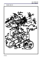
Страница 136: ...Parts 4 960 FRONTLINE PARTS MANUAL 2 ENGINE GROUP ...

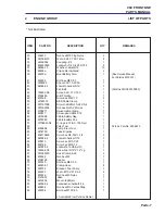
Страница 137: ...Nut hex M10 Verbus Ripp 6 10 2212073 Brckt cassapa Pump 1 11 450214 Scrw hex M10 X 25 9 12 2208174 Oil Filter 1 13 4125234 Wldmnt pump brckt 1 14 450754 Capscrw sckt M12 X 30 2 15 MBF0365 Wshr 10 5 X 25 2 X 3 2 16 001191160 Scrw hexM14 1 5X30 16 17 4125553 Mount RHMotor 1 18 4125552 Mount LHMotor 1 19 4128058 Mount Eng LhHRear 1 20 4128059 Mount Eng RHRear 1 21 450035 Bolt hex M10 X 65 2 22 450379...

Страница 138: ...Parts 6 960 FRONTLINE PARTS MANUAL 2 ENGINE GROUP ...

Страница 139: ...4Nyloc 1 53 2198211 Swivel cableClamp 1 54 450517 Screw pan Hd M4 X 12 1 55 2218088 Cable batteryNeg 1 56 2218089 Cable batteryPos 1 57 W158061 04 O ring 3 237 Id X 103 Sect 1 58 Filter Fuel 1 Perkins Part No 2656613 59 4126806 Pump Elect Fuel 1 60 2218100 Tube Dipstick 1 61 456110448 Scrw hex3 8 16X1 1 4 2 62 64006 06 Lckwshr helical7 16 3 63 450213 Scrw hex M10 X 20 1 64 450149 Scrw hex M5 X 12 ...

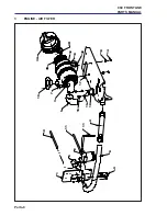
Страница 140: ...Parts 8 960 FRONTLINE PARTS MANUAL 3 ENGINE AIR FILTER 4 11 11 2 1 6 8 10 9 5 3 3C 3B 19 7 3D 3A 17 13 14 15 16 18 12 13 ...

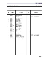
Страница 141: ...7 Elbow 90 deg 1 001925570 Hose Clamp Size 28 1 6 4124743 Sleeve TurboInlet 1 48383 Hose Clamp Size 32 2 7 4125078 Indicator 1 8 4124365 Turbo Air Inlet Pipe 1 9 001990357 Clamp 1 3 4 2 10 4127607 Hose 1 11 4128263 08 Hose 2 12 450015 M8x35 Hex Bolt 2 13 450390 M8 Plain Washer 6 14 450378 M8 Nut Nyloc 2 15 450014 M8x30 Hex Bolt 4 2 off for Fuel Filter Item 2 16 450411 M8 Spring Washer 4 2 off for ...

Страница 142: ...Parts 10 960 FRONTLINE PARTS MANUAL 4 FRAME FRONT ...

Страница 143: ... hex M12 Nyloc 14 18 450193 Scrw hex M8 X 30 3 19 001594010 Wshr 328 X 75 X 14 Ga 18 20 450378 Nut hex M8 Nyloc 17 21 W148034 01 Insul Grommet 1 I D 1 22 450214 Scrw hex M10 X 25 4 23 450391 Wshr m10 X 21 X 2 2 8 24 450379 Nut hex M10 Nyloc 4 25 64061 04 RollPin 1 8x3 4 2 26 W143036a Rod support 1 27 W138040 Clip hoodRod 1 28 001393400 Nut hex 6 32Keps 4 29 MBG3817 Brkt rodClip 1 30 64152 21 6 32x...

Страница 144: ...Parts 12 960 FRONTLINE PARTS MANUAL 5 FRAME REAR ...

Страница 145: ...083 Lanyard 2 19 450191 Scrw hex M8 X 20 4 21 452200176 Lockwshr 1 2 X 873 X 125 8 22 450214 Scrw hex M10 X 25 2 23 450391 Wshr m10 X 21 X 2 2 4 24 450379 Nut hex M10 Nyloc 2 25 113006 01 Bushing 5x 32x 19Lg 4 26 MBA5289A Wshr 8 5 X 25 5 X 3 4 27 450192 Scrw hex M8 X 25 4 28 450239 Scrw hex M12 X 20 3 29 450455 Nut hex M12 Verbus Ripp 3 30 MBG2637 Handle hood 1 31 4125539 Wldmt Rear Axle Support 1...

Страница 146: ...Parts 14 960 FRONTLINE PARTS MANUAL 5 FRAME REAR ...

Страница 147: ...48 450389 Wshr M6 X 12 5 X 1 8 2 49 001594080 Wshr 516 X 750 X 12ga 2 50 001594010 Wshr 328 X 75 X 14 Ga 8 51 450048 Bolt hex M12 X 40 1 52 MBG3000 Shim latch 2 53 64152 38 8 32x3 4 Mach Screw 4 54 001599052 Wshr 526 506X1 1 4X12ga 4 55 450390 Wshr M8 X 17 X 1 8 4 56 MBG6194 LatchHood 2 57 450866 HexM8x25Countersunk 4 5 FRAME REAR ...

Страница 148: ...Parts 16 960 FRONTLINE PARTS MANUAL 6 HOOD ...

Страница 149: ...2 2218113 Insulation hoodRear 1 3 2218118 Insulation interiorHood 1 4 2218119 Insulation hoodExterior 1 5 2218120 Insulation hoodTop 1 6 2218117 Insulation interiorLh 1 7 2218116 Insulation interiorRh 1 8 2218114 Insulation hoodLh 1 9 2218115 Insulation hoodRh 1 10 2218111 Insulation louver 5 11 009044350 Bonnet Sealing Strip 1 6 HOOD ...

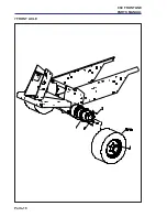
Страница 150: ...Parts 18 960 FRONTLINE PARTS MANUAL 7 FRONT AXLE ...

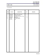
Страница 151: ...NE PARTS MANUAL Parts 19 Not illustrated 1 008007240 280cc Piston Wheel Motor 2 2 001594200 Spring Washer M14 8 3 00191160 Hex Screw M14x30 Fine Thread 8 4 008008460 Wheel Nut 10 5 4121791 Wheel Assembly 2 6 4128839 Tyre Block Pattern 1 4121792 Rim 1 7 FRONT AXLE ...

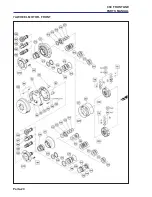
Страница 152: ...Parts 20 960 FRONTLINE PARTS MANUAL 7A WHEEL MOTOR FRONT ...

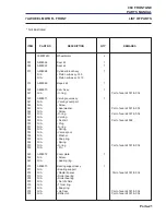
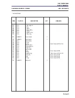
Страница 153: ...er Part of seal kit 001 002 044 N A Screw 045 N A O ring Part of seal kit 001 002 047 N A Valving 048 N A Seal kit Part of seal kit 002 050 N A Plug 051 N A O ring 052 N A Spring 053 N A Valve spool 054 N A Washer 055 N A Snap ring 056 N A Spring 057 N A O ring Part of seal kit 001 002 059 N A Pin 065 A808972 Coverplate 1 066 N A Screw 067 N A Sealing ring 070 A808973 Bearing support assy 1 071 N ...

Страница 154: ...Parts 22 960 FRONTLINE PARTS MANUAL 7A WHEEL MOTOR FRONT ...

Страница 155: ...t of studs 1 100 A808974 Brake assy 1 101 N A Brake body 102 N A Screw 106 N A O ring Part of seal kit 001 002 107 N A Brake piston 108 N A Springwasher 109 N A Snapring 110 N A Brake shaft 111 N A Seal Part of seal kit 002 112 N A Screw 113 N A Sealingring Part of seal kit 001 002 141 N A Protector Part of seal kit 002 142 N A Plug Part of seal kit 002 143 N A O ring Part of seal kit 002 135 A808...

Страница 156: ...Parts 24 960 FRONTLINE PARTS MANUAL 8 REAR AXLE ...

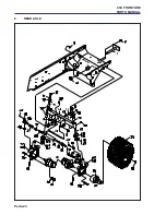
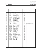
Страница 157: ...p s 1 Use Seal Kit 002300810 20 451110354 Bolt hex 1 2 13 X 3 8 21 W148141 03 Motor ME15 02 08 AAAA 2 22 450020516 Nut hex 3 4 16 Slotted 2 23 454000328 Split Pin 1 8 X 1 3 4 2 24 452200176 Lockwshr 1 2 X 873 X 125 8 25 450120055 Nut hex1 2 13 8 26 MBG0969A Wldmt Hub Wheel 2 27 008000640 Locknut1 20Unef 2 28 001341110 Nut whl1 2 2060d 8 29 842000044 Lubricator 1 4 Str 3 30 W143069 Stud cylinder 2 ...

Страница 158: ...Parts 26 960 FRONTLINE PARTS MANUAL 8A REAR WHEEL MOTOR ...

Страница 159: ...kit A820052 5 Commutator 1 6 CommutatorRing 1 7 Manifold 1 8 A800826 Rotor Set 1 9 Wear Plate 1 10 A800825 DriveLink 1 11 ThrustBearing 1 12 A800824 CouplingShaft 1 13 Bearing Bushing Inner 1 14 ThrustWasher 1 15 ThrustBearing 1 16 N A Seal 1 contained in seal kit A820052 17 N A Backup Washer 1 contained in seal kit A820052 18 Housing 1 19 Bearing Bushing Outer 1 20 N A Dirt Water Seal 1 contained...

Страница 160: ...Parts 28 960 FRONTLINE PARTS MANUAL 9 HYDRAULIC VALVES ...

Страница 161: ...et rhValveMtg 1 6 4125581 Screw Cap Head M8x100 3 7 450411 Washer Spring M8 3 10 450038 Bolt hex M10 X 80 4 11 450391 Wshr M10 X 21 X 2 2 12 12 450379 Nut hex M10 Nyloc 8 13 450213 Scrw hex M10 X 20 4 14 001090341 Bolt M10 X 160 1 15 2218225 Hyd Valve For Front Deck 1 16 450379 Nut hex M10 Nyloc 2 17 450040 Bolt hex M10 X 90 2 18 450454 Nut hex M10 Verbus Ripp 2 19 001090341 Bolt M10 X 160 1 9 HYD...

Страница 162: ...Parts 30 960 FRONTLINE PARTS MANUAL 10 HYDRALIC FILTERS ...

Страница 163: ... 1 2 X 873 X 125 8 7 64123 73 Blt hex1 2 13x1 4 8 456110090 Scrw hex1 2 13X1 1 4 4 9 178025 Filter spinOn 2 10 178024 FilterHeadModule 1 11 452200134 Lockwshr 3 8 X 683 X 094 4 12 456110066 Scrw hex 3 8 16 X 1 4 13 4124209 Manifold OilInlet 1 14 452701 Scrw hex M8 X 16 Taptite 6 15 450193 Scrw hex M8 X 30 7 16 001594010 Wshr 328 X 75 X 14 Ga 11 17 450378 Nut hex M8 Nyloc 4 18 W158061 05 O Ring 2 2...

Страница 164: ...Parts 32 960 FRONTLINE PARTS MANUAL 11 FLUID TANKS ...

Страница 165: ... 2 10 450412 Lockwshr M10 X 15 9 X 2 5 8 11 450391 Wshr M10 X 21 X 2 2 8 12 69051 01 Pipe Plug 3 8 1 13 W148027 BreatherVent 1 14 2690017 01 Ftg orb Plug 14 2 15 38471 08 Foam Closed Cell 7 8 16 09007 10 Hose 25x 8 5 1 17 2690017 03 Ftg oabPlug 1 18 2212076b Support hyd Reservoir 1 19 008296050 Switch Temp 175 F 1 20 450214 Scrw hex M10 X 25 6 21 09007 10 Hose 1 4 X 10 5 1 22 88042n HoseClamp 4 23...

Страница 166: ...Parts 34 960 FRONTLINE PARTS MANUAL 12 OPTIONAL AUXILIARY FUEL TANK ...

Страница 167: ... 10 32x1 2 R Mach Scr 5 16 64002 02 Lockwshr 10 1 17 2218046 Sender FuelLevel 1 18 148081 Gasket 1 19 2212087 Cover access 1 20 64205 041 Blt metricM10 1 5x15 2 21 64006 06 Lockwshr helical7 16 8 22 64251 004 Whsr M10 8 23 69051 01 Pipe Plug 3 8 1 24 148027 BreatherVent 1 25 2690017 01 Ftg orb Plug 14 2 26 38471 09 S foamX120 7 8 27 09007 08 S hose 5x 25x17 0 2 28 2690017 03 Ftg orb Plug 06 1 29 2...

Страница 168: ...Parts 36 960 FRONTLINE PARTS MANUAL 13 CONTROLS THROTTLE PUMP ...

Страница 169: ...901679 Sprg disc 13 X 28 X 1 4 7 172088 07 ThrottleArm 1 8 450392 Wshr m12 X 24 X 2 7 2 9 452436 Nut hex M8 Flng Nyloc 1 10 450195 Scrw hex M8 X 40 2 11 450324 Nut hexM8 4 18 148057 06 Cable throttle 1 20 128079 Rod End 1 4 Female 1 39 MBG2938A Plate Pump 1 40 2720158 Spacer6 35x15 88x9 52 1 41 2213035 Spacer Pump arm 1 42 64237 02 Locknut Nylon M6x1 00 1 43 64205 030 Blt Met M6x1 00x40 1 44 12808...

Страница 170: ...Parts 38 960 FRONTLINE PARTS MANUAL 14 CONTROL LIFT ...

Страница 171: ...Wldmnt liftLever 3 3 2218002 Valve 3SpoolLift 1 ServiceSealKit2218002 01 4 2216003 Wldmt leverSupport 1 5 450043 Bolt hex M10 X 120 1 6 450379 Nut hex M10 Nyloc 1 7 W148062 Master Link 50 Chain 3 8 450006 Bolt hex M6 X 55 2 9 450377 Nut hex M6 Nyloc 2 10 450391 Wshr M10 X 21 X 2 2 4 11 001594080 Wshr 516 X 750 X 12ga 2 14 CONTROL LIFT ...

Страница 172: ...Parts 40 960 FRONTLINE PARTS MANUAL 15 CONTROL BRAKES 10 15 20 6 7 18 18 3 16 19 9 20 17 19 13 17 20 1 1 2 3 15 18 5 20 11 4 7 18 12 8 19 21 14 ...

Страница 173: ... 6 MBG3284A Bracket M Switch 1 7 W38383 Switch Normally Closed 2 8 MBG4401 Cover Brake 1 9 MBG3883 Bracket EBV 1 10 450018 Bolt Hex M8x50 2 11 450022 Bolt Hex M8x70 2 12 450151 Screw Hex M5x16 4 13 450170 Screw Hex M6x16 2 14 450171 Screw Hex M6x20 2 15 450376 Nut Nyloc M5 4 16 450377 Nut Nyloc M6 2 17 450378 Nut Nyloc M8 4 18 450388 Washer Plain M5 8 19 450389 Washer Plain M6 4 20 450390 Washer P...

Страница 174: ...Parts 42 960 FRONTLINE PARTS MANUAL 16 CONTROLS STEERING ...

Страница 175: ...11 128079 Rod End 1 4 Female 1 12 450389 Wshr M6 x 12 5 x 1 8 2 14 450020 Bolt hex M8 x 60 1 15 450324 Nut hexM8 2 16 450379 Nut hex M10 Nyloc 5 17 38383 Switch n c 1 18 4124539 Wldmt SpeedGovenorLever 1 19 MBF1552 Spacer 2 20 4126241 Stud M10 1 21 001290379 Scrw set 1 4 20 x 1 4 2 22 W43067A Collar Set Plate 2 23 4124883 Block bearing 2 24 4124881 Wldmt Foot Pedal 1 25 450390 Washer Plain M8 3 26...

Страница 176: ...Parts 44 960 FRONTLINE PARTS MANUAL 16 CONTROLS STEERING ...

Страница 177: ...arness 1 53 450005 Bolt hex M6 x 50 4 54 001190042 Scrw rndHdNo10 24X1 2 4 55 001393298 Nut hexNo10 24Nyloc 4 56 450001 Bolt hex M6 X 30 1 57 450323 Nut hexM6 1 58 450377 Nut hex M6 Nyloc 1 59 001393298 Nut hexNo10 24Nyloc 8 60 001190042 Scrw rndHdNo10 24X1 2 8 61 008239720 Horn 1 62 450452 Nut hex M6 Verbus Ripp 1 63 469020633 Bracket forFlash 1 64 48408 Flasher 55212v 1 65 64018 2 Blt crg1 4 20x...

Страница 178: ...Parts 46 960 FRONTLINE PARTS MANUAL 17 COOLING EXHAUST 47 50 51 54 48 49 48 46 22 21 48 43 22 21 44 43 45 ...

Страница 179: ...0379 Nut Hex M10 Nyloc 2 For 13c 14 006911730 Cooler Hyd Oil 1 15 2208079 Bottle Coolant 1 16 4128625 Wldmt Coolant Bottle Bracket 1 17 2218044 Hose RadUpper 1 18 2218045 Hose RadLower 1 19 2218006 Screen 1 20 2218086 Seal Tube 1 21 450191 Scrw Hex M8 x 20 7 22 450390 Wshr M8 x 17 x 1 8 13 23 450369 Nutsert M8 A l x 17 5 4 Use Insert Tool 2196247 24 450213 Scrw Hex M10 x 20 6 25 450391 Wshr M10 x ...

Страница 180: ...Parts 48 960 FRONTLINE PARTS MANUAL 17 COOLING EXHAUST 47 50 51 54 48 49 48 46 22 21 48 43 22 21 44 43 45 ...

Страница 181: ... 1 45 172290 Brkt LowerHanger 1 46 2213009 Pipe Muffler 1 47 4122778 Wldmt Exhaust Pipe 1 48 W048319 04 Clamp Muffler2 1 8 3 49 4122798 Pipe Exhaust 1 50 Gasket ex Manifold 1 PerkinsNumber135997030 51 450411 Washer Spring M8 4 52 450192 Scrw Hex M8 x 4 53 A691139 Cap Radiatator 1 54 450727 Screw Cap Head M8 x 40 5 55 MBG5543 Battery Brace 2 Secures Battery 56 4128648 Bracket Bug Screen LH 1 57 MBG...

Страница 182: ...Parts 50 960 FRONTLINE PARTS MANUAL 18 SEAT BREAKDOWN GRAMMER S 85 90R ...

Страница 183: ...stance Plate 1 15 008173440 Bush 2 16 008199690 Back Plate 1 17 008173450 Tube 1 18 008173460 Spring 1 19 008173470 Washer 2 20 008173480 Screw 2 21 008173490 Tube 1 22 008173500 Edge Strip 1 23 008173510 Edge Strip 1 24 008173530 Distance Piece 1 25 008173540 Seat Plate 1 26 008199650 Pin 1 27 008199660 Detent 1 28 008173550 MountingLh 1 29 008199670 Rod 1 30 008173560 Bush 1 31 008173570 Distanc...

Страница 184: ...Parts 52 960 FRONTLINE PARTS MANUAL S 85 90R 18 SEAT BREAKDOWN GRAMMER ...

Страница 185: ...47 008199740 Washer 1 48 N A Plug 2 49 008199550 Arm Rest RH 1 50 N A Screw 2 51 N A SupportRH 1 52 N A Pin 2 53 008199850 Arm Rest Assy RH 1 54 008173630 Arm Rest LH 1 55 N A SupportLH 1 56 008199860 Arm Rest Assy LH 1 59 N A CoverAssy 1 60 N A Screw 1 61 N A Seat Belt Fixed 1 62 N A Seat Belt Reel 1 63 N A Screw 64 N A Washer 18 SEAT BREAKDOWN GRAMMER ...

Страница 186: ...Parts 54 960 FRONTLINE PARTS MANUAL 19 SEAT SUSPENSION GRAMMER DS85H ...

Страница 187: ...3760 Plate 1 20 008173770 Suspension Assy 1 22 008173780 Roller 4 23 008173790 Pin 1 24 008173800 Bush 4 25 008173810 Spring 2 26 008173820 Plate 1 27 008173830 Plate 2 28 008173840 Bolt 1 29 008173850 Pin 1 30 008199900 Hinge 1 31 008173860 Washer 1 32 008173870 Bearing 1 33 008173880 Nut 1 34 008173890 Handle 1 35 008173900 Lever Assy 1 36 008199920 Weight Adjuster 1 37 008199410 Spring 2 38 008...

Страница 188: ...Parts 56 960 FRONTLINE PARTS MANUAL 20 PUSHARM ASSEMBLY ...

Страница 189: ...002301110 7 MBF1929 Wldmt push Arm Pin 2 8 W038383 Switch n c 1 9 W172359 Plate push Arm Sw 1 10 2212109 Bracket switch Mtg 1 11 001190042 Scrw rndHdNo10 24X1 2 4 12 001393298 Nut hexNo10 24Nyloc 4 13 450191 Scrw hex M8 X 20 2 14 450378 Nut hex M8 Nyloc 2 15 001190377 Scrw wlf1 4 20X1 2 2 16 456110016 Scrw hex 1 4 20 X 3 4 2 17 001399121 Nut hex 1 4 20 Nyloc 2 18 001594080 Wshr 516 X 750 X 12ga 8 ...

Страница 190: ...Parts 58 960 FRONTLINE PARTS MANUAL 21 DECK MOUNTING ...

Страница 191: ...18 MBF1922 7 Wldmt armRearRh 1 IncludesItem83 19 456110503 Scrw hex 1 4 20 X 5 8 6 20 MBF2200 Wldmt pin 4 Fitted From Under Arm Not As Shown MBG5349 Clamp Ring Wshr 4 Used Item 20 450382 Nut hex M16 Nyloc 4 Used Item 20 002993013 Lubricator M6Str 4 Used Item 20 451488 Pin spirol 8 X 20 4 Used Item 20 21 W176061 7 Wldmt Swing Arm Rear 2 22 W176059 7 Wldmt Swing Arm LF 1 23 W176060 7 Wldmt Swing Arm...

Страница 192: ...Parts 60 960 FRONTLINE PARTS MANUAL 21 DECK MOUNTING ...

Страница 193: ...2110 Brckt RearRoller 2 58 48429 Spring Extension 2 59 450019 Bolt hex M8 X 55 4 60 450379 Nut hex M10 Nyloc 4 61 178097 01 Clamp Tube 7 62 64123 192 Blt hex 1 4 20 X 4 1 2 5 63 001393052 Nut hex 1 4 20 Whiz 5 65 148090 03 Clamp 2 66 450389 Wshr M6 X 12 5 X 1 8 11 MBG5502 Bracket tubeSupport 2 67 450377 Nut hex M6 Nyloc 2 68 450003 Bolt hex M6 X 40 2 69 2212116 Bracket Stop 2 70 456110016 Scrw hex...

Страница 194: ...Parts 62 960 FRONTLINE PARTS MANUAL 22 46CC M46 20788 SERVO TRANSMISSION PUMP ...

Страница 195: ... A800731 ChargeReliefValvePoppet 1 118 A800732 NeedleBearing 7 131 A800733 ShaftBearing 1 132 A800734 Circlip 2 133 A800735 Circlip 2 155 A800736 ChargePumpHousing 1 202 A800737 Swash Plate Housing 1 930 A800738 Adjuster Screw 1 1001 A800739 Bypass Valve 1 1102 A800740 ReliefValveCartridge 1 1103 A800741 ReliefValveCartridge 1 1210 A800742 Adjuster Screw 1 1401 A800743 Oriface 1 1402 A800744 Sleev...

Страница 196: ... MANUAL 23 TRANSMISSION VALVE Port B SAE 12 Ports C C1 E E1 SAE 10 Ports F T SAE 6 Maximum Input Flow 140 L M Maximum Divided Combined Flow 70 L M Maximum Working Pressure F 280 Bar B C E 230 Bar TORQUE SETTINGS REFER TO SECTION 1 ...

Страница 197: ...nifold 1 2 008089830 FlowDivider Combiner 1 3 008089850 Piloted Popet type logic element 2 4 008089860 PilotedDirectionalValve 1 5 008089870 SolenoidValve 1 6 4132063 1 4 UNF Jet Drilled 1 8mm Dia 1 7 008089880 ShuttleValve 1 8 008089940 CheckValve 2 9 008089960 Blanking Plug Viton 2 10 4115573 BlankingPlug Viton 1 23 TRANSMISSION VALVE ...

Страница 198: ...Parts 66 960 FRONTLINE PARTS MANUAL 24 WING DECK VALVE Ports P M1 M2 T SAE 10 Ports C C SAE 6 Ports G G SAE 4 Maximum Working Pressure 220 Bar TORQUE SETTINGS REFER TO SECTION 1 ...

Страница 199: ... 0 V 35 M210 1 178102 01 SK10 2V B 2 178102 13 RV10 22H 0 V006 3 0 1 178102 01 SK10 2V T 3 178102 31 CV10 20 O V 70 1 178102 01 SK10 2V T 4 178102 14 Pilot Piston 7013200S 1 5 178102 16 SV10 21W 0 V 00 1 178102 01 SK10 2V T 6 178102 17 Coil6351012 1 7 178102 19 SAE Plug 6 178102 09 Seal 8 178102 18 SAE Plug 1 178102 10 Seal 24 WING DECK VALVE ...

Страница 200: ...Parts 68 960 FRONTLINE PARTS MANUAL 25 DECK VALVE Port T SAE 12 Ports P M1 M2 SAE 10 Port R SAE 8 Port G SAE 4 TORQUE SETTINGS REFER TO SECTION 1 ...

Страница 201: ... SK08 2V T 2 178102 59 CV10 20T 0 V 300 1 178102 01 SK10 2V T 3 178102 79 RV10 22H 0 V 35 32 1 178102 02 SK10 2V B 4 178102 34 RV10 2005H Viton 1 178102 02 SK10 2V B 5 178102 16 SV10 21W 0 V 00 1 178102 01 SK10 2V T 6 178102 17 Coil6351012 1 7 178102 57 Pilot Piston 7013200S 1 8 178102 19 SAE Plug 1 178102 09 Seal 9 178102 18 SAE Plug 4 178102 10 Seal 25 DECK VALVE ...

Страница 202: ...Parts 70 960 FRONTLINE PARTS MANUAL 26 1 HYDRAULIC DIAGRAM TRANSMISSIOM ...

Страница 203: ... 05 90 M M 1 ORS x 7 8 SAE 6 F8 W158007 07 90 M M 1 3 16 ORS x 1 1 16 SAE 4 F9 158007 14 FITTING 90ORS ORB 2 F10 W158010 01 FITTING ORSRUNTREE 1 F11 W158058 04 90 M M 9 16 SAE x 38 BARB 3 F12 W158061 01 O RING 364 ID x 07 SECT 1 F13 W158061 05 O RING 2 234 ID x 139 SECT 2 F14 W158067 01 FTG BLKHD M M 11 16 ORS 4 F15 W158067 02 FTG BLKHD M M 1 ORS 3 F16 158067 04 FTG BLKHDORS ORS 1 F17 2690019 01 F...

Страница 204: ...Parts 72 960 FRONTLINE PARTS MANUAL 26 1 HYDRAULIC DIAGRAM TRANSMISSIOM ...

Страница 205: ... ORS x 7 8 SAE 6 F324 W158006 11 FTG M M 1 ORS x 1 1 16 SAE 3 F325 2498420 45 M M 1 ORS x 1 1 16 SAE 2 F326 W158011 01 TEE M M M 11 16 ORS 2 F327 2498400 TEE M F M 11 16 ORS 3 F328 2590710 90 M M 9 16 ORS x 3 8 BSPP 6 F329 2590480 TEE M F M 9 16 ORS 3 F330 2590910 TEE M M M1 3 16 2 ORSx1 5 16 1 F331 002498870 TEE M F M 1 3 16 ORS 1 F332 02498900 TEST POINT 1 4 BSPP x 1 3 16 2 F333 02449006 TESTPOI...

Страница 206: ...Parts 74 960 FRONTLINE PARTS MANUAL 26 2 HYDRAULIC DIAGRAM UNIT DRIVE ...

Страница 207: ...NG 90ORS ORB 2 F10 W158010 01 FITTING ORSRUNTREE 1 F11 W158058 04 90 M M 9 16 SAE x 38 BARB 3 F12 W158061 01 O RING 364 ID x 07 SECT 1 F13 W158061 05 O RING 2 234 ID x 139 SECT 2 F14 W158067 01 FTG BLKHD M M 11 16 ORS 4 F15 W158067 02 FTG BLKHD M M 1 ORS 3 F16 158067 04 FTG BLKHDORS ORS 1 F17 2690019 01 FITTING ORSSTR STEM 2 F19 58026 01 3 WAY CONNECTOR 3 8 3 F20 W69055 01 90 BLKHD M M 11 16 ORS 5...

Страница 208: ...Parts 76 960 FRONTLINE PARTS MANUAL 26 2 HYDRAULIC DIAGRAM UNIT DRIVE ...

Страница 209: ... 1925220 HOSE CLAMP 8 22 10 F318 158006 14 FITTING ORB ORS 2 F319 2218126 TUBE CHECKVALVEPORT2 2 F321 148090 03 HOSE SUPPORT5 8 2 F322 469021633 HOSE CLIP LARGE H980407 2 F323 002535040 45 M M 1 ORS x 7 8 SAE 6 F324 W158006 11 FTG M M 1 ORS x 1 1 16 SAE 3 F325 2498420 45 M M 1 ORS x 1 1 16 SAE 2 F326 W158011 01 TEE M M M 11 16 ORS 2 F327 2498400 TEE M F M 11 16 ORS 3 F328 2590710 90 M M 9 16 ORS x...

Страница 210: ...Parts 78 960 FRONTLINE PARTS MANUAL HYDRAULICDIAGRAM 26 3 HYDRAULIC DIAGRAM STEERING LIFT ...

Страница 211: ... 4 F9 158007 14 FITTING 90ORS ORB 2 F10 W158010 01 FITTING ORSRUNTREE 1 F11 W158058 04 90 M M 9 16 SAE x 38 BARB 3 F12 W158061 01 O RING 364 ID x 07 SECT 1 F13 W158061 05 O RING 2 234 ID x 139 SECT 2 F14 W158067 01 FTG BLKHD M M 11 16 ORS 4 F15 W158067 02 FTG BLKHD M M 1 ORS 3 F16 158067 04 FTG BLKHDORS ORS 1 F17 2690019 01 FITTING ORSSTR STEM 2 F19 58026 01 3 WAY CONNECTOR 3 8 3 F20 W69055 01 90 ...

Страница 212: ...Parts 80 960 FRONTLINE PARTS MANUAL 26 3 HYDRAULIC DIAGRAM STEERING LIFT ...

Страница 213: ...17 1925220 HOSE CLAMP 8 22 10 F318 158006 14 FITTING ORB ORS 2 F319 2218126 TUBE CHECKVALVEPORT2 2 F321 148090 03 HOSE SUPPORT5 8 2 F322 469021633 HOSE CLIP LARGE H980407 2 F323 002535040 45 M M 1 ORS x 7 8 SAE 6 F324 W158006 11 FTG M M 1 ORS x 1 1 16 SAE 3 F325 2498420 45 M M 1 ORS x 1 1 16 SAE 2 F326 W158011 01 TEE M M M 11 16 ORS 2 F327 2498400 TEE M F M 11 16 ORS 3 F328 2590710 90 M M 9 16 ORS...

Страница 214: ...ONTLINE PARTS MANUAL 27 MAIN WIRING DIAGRAM 10 AMP FUSE HOLDER 7 FUSE HOLDER 6 10 AMP 20 AMP 10 AMP 10 AMP 10 AMP 10 AMP 20 AMP 20 AMP 10 AMP 10 AMP 10 AMP 10 AMP 20 AMP FUSE HOLDER 5 8H 8G 8E 8D 8B 8A 8J 8K 8I 8C 8F ...

Страница 215: ...se 10 Amp Hazard Lights 1 7F 008233164 Fuse 10 Amp Indicators 1 8A 008244553 FlasherUnit 1 8B 008244700 Relay 1 2 Size R H Deck 1 8C 008244700 Relay 1 2 Size Cen Deck 1 8D 008244700 Relay 1 2 Size L H Deck 1 8E 008244700 Relay 1 2 Size Cutter Master 1 8F 008244690 Relay Starter 1 8G 008244700 Relay 1 2 Size Horn 1 8H 008244700 Relay 1 2 Size Alarm 1 8I 008244660 Relay Accessory 1 8J 008244700 Rela...

Страница 216: ...Parts 84 960 FRONTLINE PARTS MANUAL 27 MAIN WIRING DIAGRAM ...

Страница 217: ...S MANUAL Parts 85 Not illustrated 23 178100 Valve RHDeck 1 24 178100 Valve LHDeck 1 25 2218226 Valve FrontDeck 1 27 4126806 Pump Elect Fuel 1 28 008296040 Switch WaterTemp 1 PerkinsNo 385720231 29 W108208 Parking Brake Switch 1 30 W38382 Switch 2 27 MAIN WIRING DIAGRAM ...

Страница 218: ...Parts 86 960 FRONTLINE PARTS MANUAL 28 INSTRUMENT PANEL WIRING DIAGRAM ...

Страница 219: ...rness Introment 1 5 MBG5127a InstrumentPanel 1 6 Switch ignition 1 PerkinsNumber385201160 7 W178092 04 S FuelGauge 1 8 W178092 03 S WaterTempGauge 1 9 008231870 Pilot Lamp Twin 12 Volt 2 10 008295640 Lens Battery 1 11 008295630 Oil Pressure Lens 1 12 008295710 Lens HydraulicOil 1 13 008295650 Lens EngPre heatGreen 1 14 008295465 Pto Rocker Switch 1 16 008295870 Pto Lens 1 17 178092 22 Light For Ro...

Страница 220: ...Parts 88 960 FRONTLINE PARTS MANUAL 29a BADGES 4 3 17 6 7 ...

Страница 221: ... FRONTLINE PARTS MANUAL Parts 89 Not illustrated 29a BADGES PartofIDL124 3 4125618 Decal R H Swoosh 960 1 4 4125619 Decal L H Swoosh 960 1 6 4124185 Decal Ransomes Emblem 1 7 4124006 Decal Ransomes Steering Wheel 1 17 4125605 Decal 10 Ransomes Lettering 1 ...

Страница 222: ...Parts 90 960 FRONTLINE PARTS MANUAL 29b DECALS MACHINE ...

Страница 223: ...dB 1 2 2720293 Label UK Seat Plate 1 5 4118415 Decal Coolant hazard 1 8 009034880 Decal Fan 1 9 009034900 Decal Belt 1 10 009034890 Decal Bystander Warning 1 11 009034910 Decal Instructions 1 12 009034920 Decal Hot 1 13 009114100 Decal Battery 1 14 009239210 Decal Pressure 1 15 4125899 Decal Set HR960 1 16 4126319 Decal Air Cleaner end Cap 1 17 009036216 Coat of Arms 1 ...

Страница 224: ...Parts 92 960 FRONTLINE PARTS MANUAL 29c DECALS LH RH DECKS K K S 1 2 H 1 2 S 1 2 1 2 S H K K K 1 2 S H K 1 2 S S ...

Страница 225: ...Wash EC 1 3 009034890 Decal Bystander Warning 1 4 009034900 Decal Belt 1 5 009034910 Decal Instruction 1 6 009034960 Decal Rotating Blades 1 Decals Left Hand Deck IDL125 1 009239720 Decal Hieght of cut 1 2 2000643 Label Wing Deck Wash EC 1 3 009034890 Decal Bystander Warning 1 4 009034900 Decal Belt 1 5 009034910 Decal Instruction 1 6 009034960 Decal Rotating Blades 1 29c DECALS LH RH DECKS ...

Страница 226: ...Parts 94 960 FRONTLINE PARTS MANUAL 29d DECALS FRONT DECK 2 1 2 1 S H K K 1 2 S H K K S 1 2 S ...

Страница 227: ...strated Decals Centre Deck IDL126 1 009239270 Decal Hieght of cut 1 2 2000643 Label Wing Deck Wash EC 1 3 009034890 Decal Bystander Warning 1 4 009034900 Decal Belt 1 5 009034910 Decal Instruction 1 6 009034960 Decal Rotating Blades 1 7 4125553 Decal Ransomes Centre Deck 1 29d DECALS FRONT DECK ...

Страница 228: ...Parts 96 960 FRONTLINE PARTS MANUAL 30 FRONT CUTTING DECK ...

Страница 229: ...8195 Pulley Ja 1 19 450191 Blt M8 X 20 4 20 W178121 Belt CenterDeck 1 21 Mbg6038 Pulley 5 75Od 3 22 48450 16 Foam 5x4 0x 5 2 23 456110066 Scrw hex 3 8 16 X 1 2 24 64188 40 1 2 X 2 5 8 Clevis Pin 2 25 46335 ShaftAsm Roller 5 26 2198153 Roller 3 7 27 W146067 Wldmt RollerShaft 1 28 Mbf1931a 6 Wldmt FrontDeck Hr9510 1 29 2216071 6 Wldmt Support Arm RH 1 30 450222 Scrw hex M10 X 65 1 31 450325 Nut hexM...

Страница 230: ...Parts 98 960 FRONTLINE PARTS MANUAL 31 CASTER WHEELS ...

Страница 231: ... X0 75 2 3 002993013 Lubricator m6 Str 1 5 MBF1939a 6 Asm Yoke 11 00 Tyre 1 6 452438 Nut hex M12 Flng Nyloc 1 7 4118873 Bolt crg M12 X 170 1 11 469009601 Quick Pin 1 12 MBG5426 Collar 1 266X2X 250 1 13 MBG5427 Collar 1 266X2X 500 3 14 450239 Scrw hex M12 X 20 4 15 450424 Lockwshr M12 X 21 X 2 5 4 31 4127119 Wheel Tyre11x4 0 5 2 DeepGrooveBearings Bearings Spacer Seals 31 CASTER WHEELS ...

Страница 232: ...Parts 100 960 FRONTLINE PARTS MANUAL 32 WING DECK ...

Страница 233: ... M16 X 70 4 13 W176061 7 Swing Arm Assy rear 2 14 MBG5427 Collar 1 266X2X 500 10 15 002190200 Bush flng1 25 X1 50 X0 75 4 16 MBF2195 6 Wldmt CasterArm 2 17 450239 Scrw hex M12 X 20 16 18 450424 Lockwshr M12 X 21 X 2 5 16 19 MBF2196 6 Wldmt Yoke Caster 2 20 450380 Nut hex M12 Nyloc 2 21 452626 Bolt crg M12 X 150 1 24 MBF2194 6 Wldmt Caster Whl Brkt 2 25 64188 29 Pin Clevis 1 2 X 6 2 26 MBF1969 Wldm...

Страница 234: ...Parts 102 960 FRONTLINE PARTS MANUAL 32 WING DECK ...

Страница 235: ...50 MBG5653 6 Cover BeltInnerLH 1 On 10 7 Models MBG5654 6 Cover BeltInnerRH 1 On 10 7 Models 51 43065A Spacer Bushing 2 52 461901679 Sprg Disc 13 X 28 X 1 4 53 453005165 Key 1 4 X 1 4 X 1 1 8 4 54 168142 03 Strip rubber 2 55 4127120 Whl 9x3 5x4 0 Filled 2 002090600 ServiceKit 1 Bearings Spacer Seals 002989470 DeckCoverFoam Ar 0 95m 9 8 Deck 002989470 DeckCoverFoam Ar 1 25m 10 7 Deck W158007 05 90 ...

Страница 236: ...Parts 104 960 FRONTLINE PARTS MANUAL 33 SPINDLE ASSEMBLY ...

Страница 237: ... 1 7 143030 Spindle 1 8 143032 Spacer Bearing 1 9 001791189 Snap Ring 1 250 1 10 143031 Spacer Seal 1 11 148071 01 V RingV 60a 2 12 450944 Scrw set M4 X 10 Cup Pnt 2 13 142108 7 Cap Spindle 1 14 112243 03 Blade 1 Use 112243 02 On 9 8 Wing Decks Qty 4 15 450393 Wshr M16 X 30 X 3 3 1 16 001009770 Bolt hex 5 8 18 X 7 3 4 1 17 64209 03 Spring Washer 67 Id 1 18 450020176 Nut hex5 8 18 1 19 450479 Scrw ...

Страница 238: ...2 2208079 BOTTLE COOLANT 47 15 2208099 SWITCH 90043 CH 14 83 19 2208139 CLAMP 47 39 2208139 CLAMP TUBE 71 F116 2208139 CLAMP TUBE 75 F116 2208139 CLAMP TUBE 79 F116 2208174 OILFILTER 5 12 2208174 OILFILTER 7 12 2212043 BRACKET OILCOOLER 47 12 2212045 GUSSET RH 13 9 2212046 GUSSET LH 13 8 2212049 BRACKET VALVEMTG 29 4 2212064 COVER ACCESS 11 10 2212072 SCREEN HOOD 13 1 2212073 BRCKT CASSAPAPUMP 5 1...

Страница 239: ...539 SPEEDGOVENORLEVER 43 18 4124596 WLDMT AIRCLEANEROUTLET 9 18 4124654 HOSE AIRCLEANER 9 4 4124737 ELBOW 90 DEG 9 5 4124743 SLEEVE TURBOINLET 9 6 4124879 45DEGREEFITTING 73 F339 4124879 45DEGREEFITTING 77 F339 4124879 45DEGREEFITTING 81 F339 4124881 WLDMT FOOTPEDAL 43 24 4124883 BLOCK BEARING 43 23 4125078 INDICATOR 9 7 4125140 WLDMT TOWER 11 3 4125141 WLDMT LHFRAMERAIL 11 5 4125141 WLDMT LHFRAME...

Страница 240: ...ENT 79 F202 W158006 08 FTG M M 71 F104 W158006 08 FTG M M 75 F104 W158006 08 FTG M M1 79 F104 W158006 11 FTG M M 1 ORS X 1 1 16 SAE 73 F324 W158006 11 FTG M M 1 ORS X 1 1 16 SAE 77 F324 W158006 11 FTG M M 1 ORS X 1 1 16 SAE 81 F324 W158007 01 90 M M 11 16 ORS X 9 16 SAE 71 F1 W158007 01 90 M M 11 16 ORS X 9 16 SAE 75 F1 W158007 01 90 M M 11 16 ORS X 9 16 SAE 79 F1 W158007 05 90 M M 1 ORS X 7 8 SAE...

Страница 241: ... LUBRICATOR M6STR 103 45 002993160 LUBRICATOR M6X90DEG 105 6 006911730 COOLER HYD OIL 47 14 006911730 OILCOOLER 71 77 006911730 OILCOOLER 75 77 007997210 HOSE FUELTANKVENT 35 4 008000640 LOCKNUT1 20UNEF 25 27 008007120 46CCM46TRANSMISSIONPUMP5 5 008007120 46CCM46TRANSMISSIONPUMP7 5 008007120 TRANSMISSIONPUMP 63 008007120 TRANSMISSIONPUMP 71 2 008007240 280CCPISTONWHEELMOTOR 19 1 008007240 WHEELMOT...

Страница 242: ...08244700 RELAY 1 2 SIZE CUT MASTER 83 8E 008244700 RELAY 1 2 SIZE HORN 83 8G 008244700 RELAY 1 2 SIZE ALARM 83 8H 008244700 RELAY 1 2 SIZE ACC CTRL 83 8J 008244740 RELAY 70 AMP 83 9 008295211 BLANKINGPLUG 87 1 008295465 PTOROCKERSWITCH 87 14 008295630 OILPRESSURELENS 87 11 008295640 LENS BATTERY 87 10 008295650 LENS ENGPRE HEATGREEN 87 13 008295710 LENS HYDRAULICOIL 87 12 008295870 PTOLENS 87 16 0...

Страница 243: ...13200S 67 4 178102 16 SV10 21W 0 V 00 67 5 178102 16 SV10 21W 0 V 00 69 5 178102 17 COIL 6351012 67 6 178102 17 COIL 6351012 69 6 178102 18 SAEPLUG 67 8 178102 18 SAEPLUG 69 9 178102 19 SAEPLUG 67 7 178102 19 SAEPLUG 69 8 178102 31 CV10 20 O V 70 67 3 178102 34 RV10 2005H VITON 69 4 178102 42 RV10 22H 0 V 35 M210 67 1 178102 57 PILOTPISTON7013200S 69 7 178102 58 CV08 20 0 V 80 69 1 178102 59 CV10 ...

Страница 244: ... LOUVREPANEL 13 7A MBF1921 7 WLDMT ARMREARLH 59 17 MBF1922 7 WLDMT ARMREARRH 59 18 MBF1925 7 WLDMT PUSHARMLH 57 1 MBF1926 7 WLDMT PUSHARMRH 57 2 MBF1929 WLDMT PUSHARMPIN 57 7 MBF1931A 6 WLDMT FRONTDECK HR9510 97 28 MBF1932 6 WLDMT DECKCOVER 97 1 MBF1937 6 WLDMT CASTERSUPPORT 99 1 MBF1939A 6 ASM YOKE 11 00 TYRE 99 5 MBF1947 6 WLDMT WINGDECKLH 101 30 MBF1948 6 WLDMT WINGDECKRH 101 MBF1958 WLDMT ADJP...

Страница 245: ...X 07 SECT 75 F12 W158061 01 O RING 364 ID X 07 SECT 79 F12 W158061 04 O RING 3 237 ID X 103 SECT 7 57 W158061 04 O RING 3 237 ID X 103 SECT 73 F308 W158061 04 O RING 3 237 ID X 103 SECT 77 F308 W158061 04 O RING 3 237 ID X 103 SECT 81 F308 W158061 05 O RING 2 234 ID X 139 SECT 31 18 W158061 05 O RING 2 234 ID X 139 SECT 71 F13 W158061 05 O RING 2 234 ID X 139 SECT 75 F13 W158061 05 O RING 2 234 ID...

Страница 246: ......

Страница 247: ......

Страница 248: ...erzekerd door de ISO 9001 registratie die op al onze productielocaties van toepassing is Een wereldwijd dealernet en technici met een fabriekopleiding voorzien mede dankzij de back up van Ransomes Jacobsen Parts Xpress in een betrouwbare productondersteuning van hoge kwaliteit Kwaliteit prestatie en ondersteuning van wereldklasse Geräte der Firma Ransomes Jacobsen Limited werden nach höchst anspru...

Отзывы: