background image

B

en-5 

Safety, Operation, & Maintenance Manual

Lithium

SAFETY

SAFETY

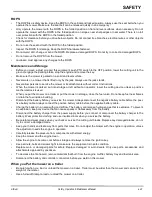
HOW TO OPERATE SAFELY

____________________________________________________________

Safe Operation

Read the Operator’s Manual and other training material. If the operator or technician can not read this manual, the

owner is responsible to describe this material to the operators and technicians. Manuals in additional languages may

be available on the Jacobsen or Ransomes Jacobsen website.

Read all of the instructions for this mower carefully. Know the controls and the correct operation of the equipment.

Children or persons who do not understand these instructions must not use the mower. The local regulations can

limit the age of the operator.

Never use a mower near persons, including children or animals.

Remember that the operator or owner is responsible for accidents or hazards that occur to other persons or their

property.

Never carry passengers.

Never allow persons to operate or service the mower or its attachments without correct instructions.

Do not operate equipment while tired, sick or after you use alcohol or drugs.

Preparation

When you operate the mower, wear correct clothing, slip resistant work shoes or boots, work gloves, hard hat, safety

glasses and hearing protection. Long hair, loose clothing or jewelry can be caught in moving parts.

Do not operate the equipment with the Interlock System disconnected or the system does not operate correctly. Do

not disconnect or prevent the operation of any switch.

Never operate equipment that is not in correct order or without decals, guards, shields, deflectors or other protective

devices fastened.

Inspect the mower before you operate the mower. Check the tire pressure, engine oil level, the radiator coolant level

and the air cleaner indicator. Fuel is flammable. Use caution when you add the fuel to the mower.

Operate  the  mower  in  daylight  or  in  good  artificial  light.  Use  caution  when  you  operate  the  mower  during  bad

weather. Never operate the mower with lightning in the area.

Inspect the area to select the accessories and attachments that are needed to correctly and safely do the job. Only

use parts, accessories and attachments approved by Jacobsen.

Be careful of holes in the terrain and other hazards that are not visible.

Inspect the area where the equipment is operated. Remove all objects you can find before you operate. Be careful of

obstructions above the ground (low tree limbs, electrical wires) and also underground obstacles (sprinklers, pipes,

tree roots). Enter a new area carefully. Look for possible hazards.

Inspect the cutting system before you start the mower. Make sure the blades are free to rotate. When you rotate one

blade, other blades can rotate.


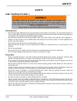
WARNING

EQUIPMENT OPERATED INCORRECTLY OR WITHOUT TRAINING CAN BE DANGEROUS.


Know the location and correct operation of controls. Operators without experience must 

receive instruction from another person that knows the correct operation of the equipment 

before you operate the mower.

Only use parts, accessories and attachments approved by Jacobsen.

!

Содержание 10029194

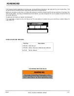
Страница 1: ...who use and maintain this machine should be trained in its proper use warned of its dangers and must read the entire manual before attempting to set up operate adjust or service the machine When Perfo...

Страница 2: ...reference during operation Before you operate your machine you and each operator you employ should read the manual carefully in its entirety By following the safety operating and maintenance instruct...

Страница 3: ...CTION 45 INTERLOCK SYSTEM 45 OPERATING PROCEDURES 46 STARTING 47 STOPPING PARKING 48 TO DRIVE TRANSPORT 49 CENTER REEL DELAY 49 OVERLOAD PROTECTION 49 MOWING 49 HILLSIDE OPERATION 51 LOADING MOWER ON...

Страница 4: ...HOOD STOPS 84 LIFT STOPS 84 HEADLIGHT ADJUSTMENT 85 STEERING SENSOR ADJUSTMENT 85 TORQUE SPECIFICATION 86 SPECIFIC TORQUE 87 LDU ERROR CODES GENERAL INFORMATION 89 SYSTEM ERROR CODES 89 REEL CONTROL U...

Страница 5: ...e correctly Do not disconnect or prevent the operation of any switch Never operate equipment that is not in correct order or without decals guards shields deflectors or other protective devices fasten...

Страница 6: ...hazards that are not visible When you drive in the reverse direction look behind you and down to make sure the path is clear Do not operate the cutting units when you drive in the reverse direction U...

Страница 7: ...the fuel valve Do not keep fuel near flames or drain the fuel inside a building Disconnect the battery before you service the mower Always disconnect the negative battery cable before the posi tive b...

Страница 8: ...ace By following all instructions in this manual you will prolong the life of your mower and maintain its maximum efficiency Adjustments and maintenance should always be performed by a qualified techn...

Страница 9: ...ade Options 7 9 11 or 15 blades Cutting Width 62 in 157 5 cm Cutting Frequency Variable See See Frequency of Cut on page 34 Height of Cut Range 1 16 to 7 16 in 0 16 to 1 11 cm MOWER Tires 18 x 10 5 8...

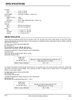
Страница 10: ...6 42 EC By compliance to The Lawnmower Standard BS EN ISO 5395 3 Referenced to Hand Arm BS EN ISO20643 2008 Information Supplied for Physical Agents Directive 2002 44 EC By reference to Hand Arm Stand...

Страница 11: ...Weights and Dimensions Dimensions Inches cm Length Grass Catchers On 101 256 5 Height Top of ROPS 79 3 201 4 Wheel Base 52 132 1 Width Mowing Position 67 7 172 0 Width Wheel 59 150 0 Turning Radius 1...

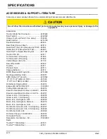
Страница 12: ...ROPS Mounted LED Light Kit 4214980 Discharger Battery Units 892857 ASM Catcher 22 w notch 4239562 25 X 5 X 22 GMR LH DRV 067995 5 X 5 X 22 GMR LH DRV 067996 Kit Deflector Clipping E322 062814 Eclipse...

Страница 13: ...68613 Grooved Front Roller Aluminum 68614 High Cut Roller 15 16 in 68634 Solid Tube Steel Roller with Scraper 68641 Grooved Segmented Roller 68673 Rear Roller Scraper 338735 Solid Tube Rear Roller 100...

Страница 14: ...en 14 Safety Operation Maintenance Manual Notes Lithium SPECIFICATIONS...

Страница 15: ...elds in place and hardware securely fastened Keep hands feet and clothing away from moving parts Before you clean adjust or repair this equipment disengage all drives engage parking brake and stop eng...

Страница 16: ...ing decals They are critical to the safe operation of the mower REPLACE DAMAGED DECALS IMMEDIATELY DANGER To prevent injury disengage all drives engage parking brake stop engine and remove key before...

Страница 17: ...IDS Use of starting assist fluids in the air intake system may be potentially explosive or cause a runaway engine condition This could result in serious engine damage Familiarize yourself with the fol...

Страница 18: ...en 18 Safety Operation Maintenance Manual DECALS Notes Lithium...

Страница 19: ...nd correct operation of controls Operators without experience must receive instruction from another person that knows the correct operation of the equipment before you operate the mower Only use parts...

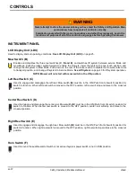
Страница 20: ...en left reel switch is moved to the OFF position left reel will stop and raise to the crosscut position Center Reel Switch D Used to engage and disengage the center reel Mow switch B must be in the ON...

Страница 21: ...tion controller does not activate until switch is moved to START position and returned to RUN START Position Used to activate the mow and traction system and start the hybrid engine if installed See S...

Страница 22: ...rse The further the pedal is pressed the faster the mower will travel Steering Wheel Tilt Lever M Push lever down to release steering column Tilt column up or down to position desired Release lever to...

Страница 23: ...ed to position armrest for operator comfort Armrest will also pivot out of the way for entering or exiting on the right side of the mower Armrest can also be adjusted to three different heights Center...

Страница 24: ...B en 24 Safety Operation Maintenance Manual CONTROLS Lithium Tie Down AD Used to secure mower to trailer for transport Fig 3 R S T U V X AA AB AC AD AD...

Страница 25: ...4 Indicator Lights The LDU has eight indicator lights to indicate system functions Power On Light Green Power On light located on left side of the LDU indicates the controller system has power A flas...

Страница 26: ...ed for each mode until a factory reset is selected The six modes are Mode 1 11 Blade Reel Use this mode when 11 blade reels are installed Reel motor operation is enabled number of reel blades are set...

Страница 27: ...Yes No Reel Motor Direction CCW CCW CCW CCW CCW CCW Maximum Mow Speed 4 mph 6 4 kph 4 mph 6 4 kph 4 mph 6 4 kph 4 mph 6 4 kph 4 mph 6 4 kph 4 mph 6 4 kph Maximum Transport Speed 9 mph 14 5 kph 9 mph 1...

Страница 28: ...he screen is for the left reel motor the number in the upper right corner of the screen is for the right reel motor and the number on the second row of the screen is for the center reel motor A fault...

Страница 29: ...me as for Operator Mode See Operator Mode on page 28 For actuator calibration screens See Lift Actuator Calibration on page 67 For backlap screens See Backlapping and Grinding on page 68 Fixed Reel Sp...

Страница 30: ...the MCU RCU and LDU CAN Network Status Displays the CAN Controller Area Network status for each of the controllers A steady non flashing controller name indicates CAN traffic has been detected from co...

Страница 31: ...ggles mower between 2WD and 3WD modes Do not set mower to 3WD if the 3WD system is not installed Fixed FOC Setting To set the fixed FOC press either of the orange buttons AM or AN on the LDU until the...

Страница 32: ...nter set mode Press the right orange button until the desired mode is on the screen then press the black button to select it See Mower Attachment Modes on page 26 for default values NOTICE If a mower...

Страница 33: ...RACTION 000 AMPS TCU HS 032F MOTOR 032F Display units Fixed FOC setting NO ALARMS DETECTED Fault Detection Screen ACTUATOR CALIBRATE Set actuator callibration CELL MAX 20C CELL MIN 19C Bettery cell te...

Страница 34: ...lue other than 0 will enable the fixed FOC mode and overrides the reel speed setting As mower travel speed increases or decreases reel speed will automatically adjust as required to maintain set FOC A...

Страница 35: ...703 1 663 1 626 2 25 0 088 0 086 0 083 0 081 0 079 0 077 0 075 0 074 0 072 3 62 2 235 2 175 2 118 2 063 2 012 1 963 1 916 1 871 1 829 2 50 0 098 0 095 0 093 0 090 0 088 0 086 0 084 0 082 0 080 4 02 2...

Страница 36: ...4 50 0 176 0 171 0 167 0 162 0 158 0 155 0 151 0 147 0 144 7 24 4 470 4 350 4 235 4 127 4 023 3 925 3 832 3 743 3 658 Mow Speed Reel RPM 1800 1850 1900 1950 2000 2050 2100 2150 2200 MPH KPH Inch cm In...

Страница 37: ...2 501 2 438 2 379 2 322 2 268 2 217 2 25 0 120 0 117 0 114 0 111 0 108 0 105 0 103 0 100 0 098 3 62 3 048 2 966 2 888 2 814 2 743 2 676 2 613 2 552 2 494 2 50 0 133 0 130 0 126 0 123 0 120 0 117 0 11...

Страница 38: ...6 84 5 757 5 602 5 454 5 314 5 182 5 055 4 935 4 820 4 711 4 50 0 240 0 234 0 227 0 222 0 216 0 211 0 206 0 201 0 196 7 24 6 096 5 931 5 775 5 627 5 486 5 353 5 225 5 104 4 988 Mow Speed Reel RPM 1800...

Страница 39: ...2 709 2 25 0 147 0 143 0 139 0 135 0 132 0 129 0 126 0 123 0 120 3 62 3 725 3 625 3 529 3 439 3 353 3 271 3 193 3 119 3 048 2 50 0 163 0 159 0 154 0 150 0 147 0 143 0 140 0 136 0 133 4 02 4 139 4 027...

Страница 40: ...333 6 179 6 031 5 891 5 757 4 50 0 293 0 285 0 278 0 271 0 264 0 258 0 251 0 246 0 240 7 24 7 451 7 249 7 059 6 878 6 706 6 542 6 386 6 238 6 096 Mow Speed Reel RPM 1800 1850 1900 1950 2000 2050 2100...

Страница 41: ...3 930 3 832 3 738 3 649 3 564 3 483 2 25 0 189 0 183 0 179 0 174 0 170 0 166 0 162 0 158 0 154 3 62 4 790 4 660 4 538 4 421 4 311 4 206 4 105 4 010 3 919 2 50 0 210 0 204 0 198 0 193 0 189 0 184 0 18...

Страница 42: ...power created by the regenerative action is sent through the resistor banks located on the right side of the machine System voltage over 60 VDC could cause damage to the controllers PARKING BRAKE____...

Страница 43: ...ow switch is turned ON Push forward and release joystick J to fully lower reels and activate reel motors Pull back on joystick and release to raise reels to crosscut position and deactivate reel motor...

Страница 44: ...en 44 Safety Operation Maintenance Manual CONTROLS Notes Lithium...

Страница 45: ...below lthe system does not start in test 1 lthe system does start in test 4 lthe traction function is not disabled in test 3 lthe mow traction and steering functions are not disabled during test 2 and...

Страница 46: ...tion of the surface Each condition will require certain adjust ments or precautions Never direct discharge of material toward bystanders nor allow anyone near the mower while in operation The owner op...

Страница 47: ...__________ 1 Sit in operator s seat make sure mow switch is OFF and traction pedal is in Neutral See INSTRUMENT PANEL on page 20 See OPERATOR CONTROLS on page 22 2 Turn system power switch to RUN Stee...

Страница 48: ...rmal conditions 1 Disengage the mow switch raise the implements and move away from the area of operation 2 Select a flat and level area to park Release traction pedal to bring the mower to a complete...

Страница 49: ...eel delay will default to a time of approximately 2 seconds There is no delay when lift system is in service mode Mow switch is OFF OVERLOAD PROTECTION ____________________________________________ The...

Страница 50: ...t pass until the center wheel is off the green this will eliminate the possibility of the tires tearing the turf during the turn 5 Each successive pass should overlap the previous one by a few inches...

Страница 51: ...e pressure is essential for maximum traction Front 16 psi 1 11 BAR Rear 20 psi 1 38 BAR WARNING To minimize the possibility of overturning the safest method for operating on hills and terraces is to t...

Страница 52: ...angle or the grade of the slope D Fig 2 Height C Result D Inches with 1 Yard Level A Millimeters with 1 Meter Level A Slope in Degrees Slope Grade 3 4 8 8 3 100 5 7 10 0 150 8 5 15 6 9 5 16 7 200 11...

Страница 53: ...OFF position and key removed If mower is unable to drive onto trailer on its own power follow this procedure 1 Follow procedure for disengaging parking brake See Towing Mower on page 54 2 Make sure r...

Страница 54: ...er end of tow bar to towing vehicle equipped with 1 7 8 in ball hitch and vehicle tow bar 10 15 in 25 4 38 1cm from ground 5 Before towing make sure reels are raised If they cannot be raised remove th...

Страница 55: ...or ZX and connect battery pack connector Fig 3 Fig 4 WARNING Do Not operate mower with parking brake manually disengaged Remove brake release harness and connect steer ing chain before returning mower...

Страница 56: ...ectly at instrument panel electrical connectors generator controllers motors or any other electrical components Do not spray water into the cooling air intake or the engine air intake Clean all plasti...

Страница 57: ...Inspect L Lubricate R Replace AR As Required Indicates initial service for new machines Not required unless engine problems occur Every 300 hours or Yearly whichever occurs first Every 500 hours or Ye...

Страница 58: ...aft and this will not be covered under war ranty after 1 year or 300 hours whichever occurs first Manual grease gun with NLGI Grade 2 Service Class LB Mobilfluid 424 or SAE 30 wt LUBRICATION CHART____...

Страница 59: ...pack is finished charging disconnect the charger cord from the vehicle If disconnecting before the charge cycle is complete it is recommended that the charger be disconnected from the wall receptacle...

Страница 60: ...elow 4 F 20 C DO NOT turn the vehicle key to the ON position drive the vehicle tow the vehicle charge the vehicle operate accessories turn the lights on if equipped Returning Vehicle to Service At the...

Страница 61: ...tdown If the battery pack temperature is within the safe to charge range the charger will operate Do not attempt to start the vehicle or charge the battery pack if the vehicle has been stored at or be...

Страница 62: ...en 62 Safety Operation Maintenance Manual BATTERIES Notes Lithium...

Страница 63: ..._____________________________________________________ Remove hex plug and check fluid level Fluid should be up to the bottom of the plug Add Mobilfluid 424 or SAE 30 wt as required to bring fluid to c...

Страница 64: ...medium to extreme wear is present hub must be replaced Do not operate mower until hub is replaced 6 Apply anti seize to axle shafts 7 Slide hubs D onto axle shafts 8 Assemble washers C and castle nuts...

Страница 65: ...ical connector G 5 Remove three screws and lock washers H securing parking brake to the motor Remove the parking brake Put the parking brake brake disk side up on a workbench 6 Extend the alignment ma...

Страница 66: ...Clean the parking brake mounting area of the front axle motor and clean the motor shaft 15 Apply a thin film of high temperature anti seize to the motor shaft 16 Assemble one o ring M into groove in c...

Страница 67: ...enter reel as required to match the crosscut position of the left reel Press the left orange button AN on the LDU to save the crosscut position for the center reel Repeat for the right reel c Lower al...

Страница 68: ...k button AL to start backlapping Selected motors will start rotating and horn will periodically chirp 6 Turn mow switch E and desired reel switches F G and H to ON position 7 Adjust reel speed between...

Страница 69: ...lbs 115 128 Nm CARE AND CLEANING _______________________________________________ Clean the mower and implements after each use Keep the equipment clean Whenever possible use compressed air to clean mo...

Страница 70: ...the load is off the tires If mower is not on jack stands check tires at regular intervals and re inflate as necessary 4 Keep the machine and all its accessories clean dry and protected from the eleme...

Страница 71: ...ht of the operator seat under the right cowling Traction controller is used to control the operation of the traction drive motor The traction controller has one green light for diagnostics Steering Co...

Страница 72: ...le green light on traction controller indicates power and faults A steady light indicates the controller is active A flash ing light indicates a traction system fault error has occurred Remove right s...

Страница 73: ...IN FUEL PULL SOLENOID FUEL HOLD SOLENOID ANTI FIRE SOLENOID GLOW PLUG RELAY START RELAY TRACTION CONTRACTOR HEAD LIGHT TCU FAN OUTPUT SPARE OUTPUT 2 SILENT MODE OUTPUT RCU Controller Diagnostic Light...

Страница 74: ...s inactive INPUTS OUTPUTS Lamp Circuit Lamp Circuit 1 CAN Low 3 Left Reel Clockwise Counter Clockwise 2 CAN High 4 Left Reel Forward Reverse 9 48 Volt DC 5 Left Reel Raise 6 Left Reel Lower 7 Right Re...

Страница 75: ...lenoid Anti Fire Solenoid 3 12 Volt DC Power In 6 Glow Plug Relay 13 Spare 12 Volt Digital Low In 7 Start Relay 14 Genset Status 8 Traction Contactor Output 15 Program Select 4 9 Head Light 16 Program...

Страница 76: ...ker Used to provide circuit protect for 48 volt contactor output except for RCU and SCU 30 Amp Circuit Breaker Used to provide circuit protec tion for SCU 50 Amp Circuit Breaker Used to provide circui...

Страница 77: ...e 86 Inspect the reel blades and bedknife to insure good sharp edges without bends or nicks The leading edge of the reel blades must be sharp free of burrs and show no signs of rounding off The bedkni...

Страница 78: ...s a closer gap near zero BEDKNIFE ADJUSTMENT _____________________________________________ See Bedknife To Reel on page 77 before making the adjustment Start adjustment at the leading end of the reel...

Страница 79: ..._____________________________ 1 Slide coupler onto reel motor shaft Check that reel motor shaft engages the coupler without excess play NOTE Loose fitting reel motor couplers will damage the motor sha...

Страница 80: ...ness clips AX onto back of connector assemblies and press clips into holes in lift arm brack etss 13 Place grass catchers AS in place on all three reels 14 Center Reel Only Connect centering spring AT...

Страница 81: ...ollar to achieve a dimension of 5 1 4 in 13 33 cm Tighten set screw 3 Measure distance from end of rod CA to face of nut CD Adjust position of nut as required to achieve a dimension of 1 8 in 0 32 cm...

Страница 82: ...ssembly 1 Remove cotter pin U slotted nut S belleville washer V shim washer W If required and half trunnion X 2 Press down on adjuster end of rod T to rotate other end of the adjuster out of the bedkn...

Страница 83: ...ess connectors for a tight connection to main harness ARMREST PIVOT ____________________________________________________ 1 Tighten or loosen pivot plunger W as required so plunger button stops the arm...

Страница 84: ...tem on page 43 1 Loosen left and right reel stop hardware AA 2 Start mower turn mow switch on and fully raise reels Shut off mower 3 Adjust left reel stop bracket AB so reel stop pin AC is resting in...

Страница 85: ...steering col umn 2 Raise or lower adjustment tab AN until headlight latches in desired detent position 3 Insert access plug STEERING SENSOR ADJUSTMENT 1 Open hood and remove controller cover 2 Loosen...

Страница 86: ...7 16 14 ft lb Nm 37 50 1 50 67 8 53 71 8 70 94 9 8 32 in lb Nm 24 2 7 30 3 4 7 16 20 ft lb Nm 42 56 9 55 74 6 59 80 0 78 105 10 24 in lb Nm 35 4 0 45 5 1 1 2 13 ft lb Nm 57 77 2 75 101 80 108 107 145...

Страница 87: ...ated Dry Lubri cated Dry M4 Nm in lb 3 83 34 5 11 45 2 0 18 M5 Nm in lb 1 80 16 2 40 21 4 63 41 6 18 54 6 63 59 8 84 78 7 75 68 10 3 910 4 0 35 M6 Nm in lb 3 05 27 4 07 36 7 87 69 10 5 93 11 3 102 15...

Страница 88: ...en 88 Safety Operation Maintenance Manual ADJUSTMENTS Notes Lithium...

Страница 89: ...top On Off Yes No Yes No Yes No Yes No Engine oil pressure low Return mower to maintenance shed Trans port speed will be limited to 3 mph 4 8 kph Diesel engine coolant above 230 vF 110 C Return mower...

Страница 90: ...t returns return mower to mainte nance shed Right Reel Motor Short Circuit Shut mower off and remove key Check reel for blockage Restart mower If fault returns return mower to mainte nance shed Left R...

Страница 91: ...of the set point Shut mower off and remove key Check reel for blockage Restart mower If fault returns return mower to mainte nance shed Excessive grass height being mowed Right Reel Motor RPM is not...

Страница 92: ...enance shed Right Actuator or wiring Short Circuit Shut off mower and remove key Check both actuator connectors for a tight connection Check visible portion of wire harness for damage Restart mower If...

Страница 93: ...urrent is 50 above the 2 min rating current Shut mower off then restart If fault returns mower must be towed back to maintenance shed Over Current Glitch The system detected that the current is over v...

Страница 94: ...short circuit in controller cabling to motor or in motor Shut mower off then restart If fault returns mower must be towed back to maintenance shed Short Circuit Glitch The system has detected a short...

Страница 95: ...C Unexpected Off The power stage was unexpectedly turned off The DC Bus charging is not finished within 10 seconds Shut mower off then restart If fault returns mower must be towed back to maintenance...

Страница 96: ...l 15V supply is out of range The valid range is 13 0V to 16 0V 5V Out of Range 3V3 Low Either the internal 5V supply is out of range or the internal 3 3V supply is too low The valid range is 4 5V to 5...

Страница 97: ...tor temp measurement may follow this event Motor temperature is above 356 F 180 C Shut mower off and wait ten minutes Restart mower If fault returns mower must be towed back to maintenance shed Not Co...

Страница 98: ...d or has short circuited The offset in the current measure ment is too high The offset is adjusted during power up of the drive Shut mower off then restart If fault returns mower must be towed back to...

Страница 99: ...dware short circuit is detected Disabling of the output is required to clear the fault Short Circuit Ch5 A hardware short circuit is detected Disabling of the output is required to clear the fault LDU...

Страница 100: ...ak over current or overload is detected High Current Ch5 The system has detected peak over current or overload is detected High Current Ch6 The system has detected peak over current or overload is det...

Страница 101: ...The measured current is below the not connected level Not Connected Ch6 The measured current is below the not connected level LDU Error Code Description Caution LED Alarm Sound ing Engine Stop Tractio...

Страница 102: ...n 200 mA of current is detected when the output should be off Curr Meas When Off Ch5 More than 200 mA of current is detected when the output should be off LDU Error Code Description Caution LED Alarm...

Страница 103: ...age drop is active across the load when OD is off This indicates that the open drain has a short circuit to B High Side Short Circuit A hardware short circuit is detected Disabling of the output is re...

Страница 104: ...nt The system has detected high peak current on high side out High Side Switch Short Circuit Supervision A short circuit of the high side controlled by the supervision CPU has been detected This indic...

Страница 105: ...Angle Offset The system has detected a checksum error on a sensor angle offset related EEPROM segment Checksum Error on Item Info The system has detected a checksum error on an item info related EEPRO...

Страница 106: ...e system detected that the voltage drop is active across the load when OD is off This indicates that the open drain has a short circuit to B Startup Sequence Error There was an error in the startup se...

Страница 107: ...ded the error limit Speed Steer Cross Error The difference between the main CPU and supervision CPU steer speed has exceeded the error limit Motor Speed Cross Error The difference between the main CPU...

Страница 108: ...s mower must be towed back to maintenance shed Dynamic Reference Ratio Error This indicates that a dynamic refer ence ratio below the allowable level has been detected Signal 1 Gain Out of Range The a...

Страница 109: ...short circuit SIN COS Sensor Not Connected Check that the unit circle is consis tent This will detect one broken sig nal even if the sensor is not rotating Sensor Supply SHC The sensor supply current...

Страница 110: ...on Plausibility Error The sensor and stator frequency have different signs Either the sensor sig nals need to be inverted or the motor phase cables are connected incor rectly The sensor speed is too h...

Страница 111: ...is too low The limit is 0 003A Sensor Supply 2 Reference Range Sensor Supply 1 Output Voltage Out of Range The sensor supply 2 reference volt age is out of of range The valid range is 4 60V to 8 30V A...

Страница 112: ...either side is invalid Loss of Ch A Loss of channel A signal or too noisy Loss of Ch B Loss of Ch B or too noisy Angle Error The difference reported by channel A and B is greater than 25 Speed Limit...

Страница 113: ...ates This indicates that one or more motor phase cables are not con nected properly or that there is a faulty current measurement sensor Frequency Above 599 Hz The electric frequency is evaluated to b...

Страница 114: ...ved within the timeout time on Rx PDO4 PDO5 Timeout Rx PDO1 has not been received within the timeout time on Rx PDO5 LDU Error Code Description Caution LED Alarm Sound ing Engine Stop Traction Stop Mo...

Страница 115: ...within the timeout time on Rx PDO9 PDO10 Timeout Rx PDO10 has not been received within the timeout time on Rx PDO10 PDO11 Timeout Rx PDO11 has not been received within the timeout time on Rx PDO11 LD...

Страница 116: ...O16 SDO1 Timeout No SDO message has been received within the timeout time on SDO1 PDO17 Timeout Rx PDO17 has not been received within the timeout time on Rx PDO17 SDO2 Timeout No SDO message has been...

Страница 117: ...ved within the timeout time on Rx PDO22 PDO23 Timeout Rx PDO23 has not been received within the timeout time on Rx PDO23 PDO24 Timeout Rx PDO24 has not been received within the timeout time on Rx PDO2...

Страница 118: ...O27 PDO28 Timeout Rx PDO28 has not been received within the timeout time on Rx PDO28 PDO29 Timeout Rx PDO29 has not been received within the timeout time on Rx PDO29 PDO30 Timeout Rx PDO30 has not bee...

Страница 119: ...eceived within the timeout time on SDO2 SDO1 Session Busy An SDO1 request is not finished and a new SDO1 request is receivedt SDO2 Session Busy An SDO2 request is not finished and a new SDO2 request i...

Страница 120: ...ed a short packet CAN Config Error CAN configuration conflict detected CRC Error The system received a message with a CRC error Sequence error The system received a message with an invalid sequence nu...

Страница 121: ...ceived CMD Busy A software failure in internal communication has occurred Supervisor Event Not Valid A supervisor event ID to replicate is not valid Independent Watchdog Timeout The MCU internal indep...

Страница 122: ...verage execution time is higher than 200U us Execution Time High 50Hz The average execution time is higher than 7000U us LDU Error Code Description Caution LED Alarm Sound ing Engine Stop Traction Sto...

Страница 123: ...cution time is higher than 400U us Execution Time Mod High Slow App The average execution time is higher than 300U us LDU Error Code Description Caution LED Alarm Sound ing Engine Stop Traction Stop M...

Страница 124: ...hat is not caught at compile time including the following Impossible configuration in flash memory Illegal error bit configured for an event Same event id on two different events Clock Failure CPU clo...

Страница 125: ...supervision CPU steer set and motor act speed has exceeded the error limit PWM Unexpected Off The power stage was unexpectedly turned off The most likely occurred as a result of a hardware detected s...

Страница 126: ...age failed due to no room in FIFO Unknown Rx Frame An internal communication message was received with unknown information CMD Busy An attempt was made to issue a new command before a previous command...

Страница 127: ...ge overlap each other Counter Unknown Bit Ranking The speed value in the received message for vehicle does not fit as configured Message Timeout Error The reception of the vehicle speed message timed...

Страница 128: ...ed within the timeout time Map Error Any PDO map has an invalid configuration SDO1 Timeout No SDO1 message was received within the timeout time SDO2 Timeout No SDO2 message was received within the tim...

Страница 129: ...te event Checksum Error There is a checksum error on any EEPROM segment with checksum Independent Watchdog Timeout The MCU internal independent watchdog was not reset in time causing the MCU to reset...

Страница 130: ...ystal or internal PLL failed to generate a stable clock The CPU will be clocked by the internal 8MHz RC oscillator 15V Out of Range The internal 15V supply is out of range The valid range is 10 56V to...

Страница 131: ...ncy failed Checkpoint2 The startup test of the checkpoint2 control flow failed Signal1 Amplitude Out of Range The adapted amplitude is too high or too low Signal2 Amplitude Out of Range The adapted am...

Страница 132: ...side output High Side Switch SHC Supervision A short circuit of the high side switch controlled by the supervision CPU was detected This indicates a hardware failure High Side Switch SHC Main A short...

Страница 133: ...lowed Positive Negative Limit The calculation of the negative start of the slow down position resulted in a positive value which is not allowed Dynamic Reference Ration Error The monitoring of the dyn...

Страница 134: ...full Ch B Signal Loss The sensor signal is suddenly lost Ch B Low Update Rate The sensor update rate is considered to be too low Ch B FIFO Overrun The first in first out buffer was full Wrong AB Diff...

Страница 135: ...ntactor coil power No Traction Movement Ensure Machine was started Check LDU Green Lightning Bolt for steady on If flashing initiate start sequence Fault Code on LDU Review any fault codes and take ap...

Страница 136: ...Mow switch is in ON position Reel enable switches are in OFF position Ensure to enable reels Machine not moving applicable if FOC is not zero Reel motors should come on when machine starts moving forw...

Страница 137: ...allow accurate evaluation of the mower s performance Another test cut should be performed after the completion of the repairs and or adjustments to verify the mower s per formance Before performing a...

Страница 138: ...s This condition is found mostly on mow ers with multiple suspended cutting units but other causes can produce the same result Washboarding may also be caused by variations in the turf Probable Cause...

Страница 139: ...pearance In most cases the wave tip to tip distance is 2 in 5 cm or less Probable Cause Remedy Mowing ground speed is too fast Reduce mowing ground speed HOC height of cut setting is too low for turf...

Страница 140: ...Cause Remedy HOC height of cut settings are different from one side of a reel to the other or from one cutting unit to another Check HOC adjustment of cutting units Worn front roller bearings Check re...

Страница 141: ...a light green or even brown patch This is usually caused by an excessively low height of cut HOC setting and or uneven turf Probable Cause Remedy HOC height of cut settings are lower than normal Chec...

Страница 142: ...rass Probable Cause Remedy Bedknife improperly adjusted Adjust reel to bedknife setting Dull reel or bedknife cutting edges Sharpen or replace reel blade and bedknife as necessary Mowing ground speed...

Страница 143: ...bedknife Damaged or unevenly worn reel Inspect reel Replace as needed Loose or missing bedknife fasteners Check bedknife screws Tighten loose screws replace missing screws Turning too aggressively Cu...

Страница 144: ...ndrowing is the deposit of clippings concentrated at one end of cutting unit s or between two cutting units forming a line in the direction of travel Probable Cause Remedy Grass is too tall Mow more o...

Страница 145: ...Inspect bedknife and reel Sharpen or replace reel and bedknife as necessary Missing loose or overtorqued bedknife screws Install replace or tighten bedknife screws to proper torque setting Mowing grou...

Страница 146: ...en 146 Safety Operation Maintenance Manual QUALITY OF CUT Notes Lithium...

Страница 147: ......

Страница 148: ...e 3 Chemin des Silos ZI du Chapitre 31100 Toulouse T 33 0 5 34 47 86 40 North South America Jacobsen 1451 Marvin Griffin Road Augusta Georgia 30906 3852 USA W www jacobsen com 1451 Marvin Griffin Road...

Отзывы: