Alarm system JA-65 MAESTRO
- 5 -
MFM53003
2. Configuration of the control panel
The metal case of the JA-65K control panel is
shipped from the factory with a built-in power
supply unit and the main board. To be able to
work as an alarm system, it should be equipped
with interface modules (R, H, X, GSM) in the
following way:
•
open the case and remove the cover
•
disconnect the power unit cable from the
main board connector K5
•
unscrew the module platform (screw on
the left side)
•
open the platform and remove it from the case
•
attach the desired modules to the positions shown in the
previous diagram
•
connect the modules' cables to the main board in the
following way:
o
60GSM or 65X = K1
o
65R = K2
o
65H = K3 (if two 65H modules are used, connect the
left module cable to the right 65H module and the
right module cable to the main board's K3 connector)
3. Control panel installation
The control panel’s case is designed to be attached to the wall,
or it can be partly installed into the wall. The rectangular hole on
the back side is for cable routing. The hole matches a KT-250
standard junction box. This allows easy specification on how to
prepare cables in a house before an alarm system installation.
•
If the
65R radio-communicating module
is used, keep in
mind that the
antenna will need about 20 cm of
clearance.
The 65R module comes with a rubber antenna,
but it can also be used with an external antenna, model AN-
01. The working range of the wireless accessories is about
100 meters under optimal conditions. However, building
materials can absorb or obstruct radio signals and
communication can also be effected by interference from
other radio signals. For these reasons, you should anticipate
a shorter working range for indoor installations.
•
Route all the cables
to the control panel (power, input
loops, outputs, telephone line etc.) before you attach the
case to the desired location.
Note: if you install the case in the wall, the hinges for both the
cover & module mounting platform should not be placed within
the wall.
3.1. Power cable wiring
The power cable should be connected only by a licensed
electrician.
The control panel is an electrical safety class II.
device with double insulation and power to its power unit must
be wired with double insulated two core power cord. No power
wire should be connected to the metal case.
Instructions:
•
use flexible 2 core (size from 0.75 to 1.5 mm
2
) double
insulated power cord. The system should not share a fuse
(10 A max) with any other household item. The fuse is used
as a circuit breaker too.
•
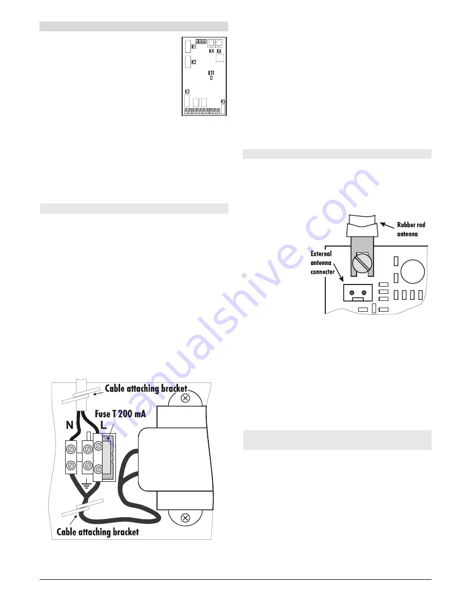
Attach the cable firmly to the board using the metal brackets.
Before you tighten the brackets, check that the wires are
tightly screwed in the terminals L and N and be sure that the
wires are not longer than shown in the diagram.
•
Check connection of the power unit cable to the connector
K5 on the main board.
4. Antenna of the JA-65R module
If the JA-65R module is installed, it will be possible to enroll wireless
detectors, controllers, a JA-60A siren, output modules and another
wireless subsystem if required. Enrollment is described in the part
11.1. The 65R module must be equipped with an antenna.
4.1 Rubber antenna use in the control panel
There is a hole on
the top of the control
panel case (remove
the plastic cap) for
the rubber antenna.
The rubber antenna
is supplied with the
65R module. Install
the antenna after
the module
mounting platform is
inserted and
screwed inside the
control panel case.
Attach the antenna to the 65R board using a screw as shown in
the diagram. The antenna must not be obstructed by any large
metal object.
4.2 External antenna use
An optional external antenna, model AN-01, can be used with
the 65R module. This antenna has a connector, which fits the
connector on the 65R module. If you use the external antenna,
the rubber antenna should not be installed. The AN-01 antenna
has a small plastic ring on its end, used to hang it from the wall.
Its active part (from the plastic ring to the coil) should be
installed vertically and should not be obstructed by any large
metal object. The antenna can be located behind furniture, etc.
5. Connectors and terminals of the main
board
In addition to the interface module connectors (K1, K2 and K3)
the main board has the following connectors:
K5 - power supply connector:
the cable from the power unit is
connected to this connector.
Do not manipulate with the
connector when it is powered.
K4, K6 - digital data jacks for the JA-60E keypad(s) and/or
for a PC interface cable.
Up to five JA-60E keypads can be
connected to a JA-65 and the maximum length of the cable can
be 500 meters. We recommend use of a CT-04 cable and RJ-44
(Jablotron) crimping connectors to make the keypad cables. The
digital data is also available on the terminals: see the following
description.
Содержание MAESTRO JA-65
Страница 1: ...JA 65 MAESTRO Alarm system installation manual...
Страница 2: ......


