


Anomalies indicator light
The ECU continuously monitors, with complex self-testing
routines, its own operating conditions as well as those of the
components connected to it and of the engine.
When anomalies are detected, the fault indicator light on the
instrument panel is lighted in manners that provide a first
indication on the severity of the problem.
Light off:
no anomaly detected or slight anomaly that
does not compromise operating safety
Light on:
significant anomaly, allowing to proceed to a
service center
Blinking light:
severe anomaly requiring immediate repairs.
If possible, shut the engine down.
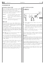
Blink code
The emission of the anomaly codes detected during self-
testing and stored in the ECU starts after pressing and
releasing the “CHECK” push-button on the relay box panel,
when the “BRIDGE - ENGINE ROOM” switch is in the
“ENGINE ROOM” position
The LED located at the side of the push-button and the
EDC indicator light on the indicator and control panel will
simultaneously signal, with two series of emissions at differ-
ent frequencies, the blink codes that indicate the anomaly
with decimal numbering.
Slow blinks
identify the area of the anomaly (engine, injec-
tors,...),
fast blinks
identify a specific anomaly.
Every time the push-button is pressed and released, only one
of the stored codes is emitted; therefore, the procedure
must be repeated until an error indication identical to the
first one is obtained, which means the entire error memory
has been analyzed.
If no anomalies are stored, the light comes on when the
push-button is pressed and comes off about 1 second after
its release, without any subsequent blinking.
NOTE
:The blink code diagnostic procedure provides indications
about current anomalies as well as past anomalies that are no
longer present when the diagnosis is carried out; therefore, it is
absolutely mandatory, at the end of every repair operation, to
erase the error memory to prevent anomalies whose cause has
already been removed from being signaled in the future.
Error deletion procedure
A.
Shut the engine down and keep the key switch in the
“OFF” position.
B.
Approach the relay box. Keeping the “CHECK” diagnos-
tic push-button (3) pressed, move the adjacent “BRIDGE
- ENGINE ROOM” switch (1) to the “ENGINE ROOM”
position, while keeping the diagnostic push-button
pressed for 8 more seconds.
C.
Release the push-button and move the “ENGINE
ROOM” switch to the “BRIDGE” position
The confirmation of the cancellation carried out will be pro-
vided by a following query of the blink code; the blink code
light (4) should not give out any code.
Recovery
The recognition of significant or severe anomalies causes the
adoption of strategies that allow to use the engine with com-
plete safety, guaranteed by limiting performance within pre-
set thresholds according to the severity of the case.
These strategies cause the reduction of the maximum values
of torque and power delivered by the engine.
In the case of intermittent anomalies, i.e. recognized by the
ECU and subsequently no longer present, performance
reduction will continue until the engine is shut down.
Normal operation will be restored only the next time the
engine is started, while the anomaly data will be “saved” in
the failure memory.
N60 ENT M37
DIAGNOSTICS
4.94
APRIL 2004
Figure 1
3
1
4
04_074_N
ECU BEHAVIOUR
Содержание N60 ENT M37
Страница 1: ...NEF ENGINE N60 ENT M37 TECHNICAL AND REPAIR MANUAL T E C H N O L O G I C A L E X C E L L E N C E ...
Страница 4: ...N60 ENT M37 IV APRIL 2004 ...
Страница 52: ...N60 ENT M37 OVERVIEW 1 52 APRIL 2004 ...
Страница 54: ...N60 ENT M37 TECHNICAL DATA 2 54 APRIL 2004 ...
Страница 60: ...N60 ENT M37 TECHNICAL DATA 2 60 APRIL 2004 ...
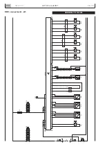
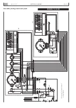
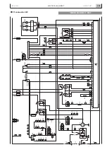
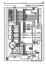
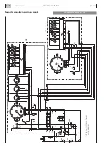
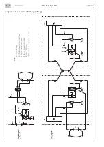
Страница 62: ...N60 ENT M37 ELECTRICAL EQUIPMENT 3 62 APRIL 2004 ...
Страница 92: ...N60 ENT M37 DIAGNOSTICS 4 92 APRIL 2004 ...
Страница 116: ...N60 ENT M37 DIAGNOSTICS 4 116 APRIL 2004 ...
Страница 118: ...N60 ENT M37 MAINTENANCE 5 118 APRIL 2004 ...
Страница 122: ...N60 ENT M37 MAINTENANCE 5 122 APRIL 2004 ...
Страница 124: ...N60 ENT M37 SERVICING OPERATIONS ON INSTALLED ENGINE 6 124 APRIL 2004 ...
Страница 139: ...SECTION 7 TOOLS Page TOOLS 141 N60 ENT M37 TOOLS 7 139 APRIL 2004 ...
Страница 140: ...N60 ENT M37 TOOLS 7 140 APRIL 2004 ...
Страница 146: ...N60 ENT M37 TOOLS 7 146 APRIL 2004 ...
Страница 156: ...APRIL 2004 OVERHAUL 8 156 N60 ENT M37 ...
Страница 164: ...APRIL 2004 OVERHAUL 8 164 N60 ENT M37 ...
Страница 181: ...OVERHAUL APRIL 2004 N60 ENT M37 8 181 ...
Страница 188: ...N60 ENT M37 OVERHAUL 8 188 APRIL 2004 ...
Страница 190: ...N60 ENT M37 SAFETY PRESCRIPTIONS 9 190 APRIL 2004 ...
Страница 193: ......