background image


9

2.2.1 Power Requirements 

Power 

The NP-600S can be powered by DC power only. The specified 
voltage range is +21 to 25 Volts DC.  This insures compatibility 
with most controller DC systems. The power conditioning circuitry 
inside the unit is accomplished by a switching power supply. The 
peak starting current can be as high as 700mA. 

Fusing 
Requirements 

If the display does not come on within 2 seconds of power up, 
remove power. An internal fuse will prevent damage if the polarity 
of the DC power is incorrect. Check wiring to insure proper 
connections and try to power up again. 

Caution 
High Voltage 

An Internal fuse will prevent damage for over voltage condition 
however it isn’t guaranteed. 

DC voltage sources should provide proper isolation from main AC 
power and similar hazards.


Caution 
Emergency 
Stop 

A Hard-wired EMERGENCY STOP should be fitted in any system 
using an NP-600S to comply with ICS Safety Recommendations. 

Caution 
Supply Voltage 
Condition 

Do not power the NP-600S and inductive DC loads, or input 
circuitry to the controller, with the same power supply. Note: The 24 
VDC output from some controllers may not have enough current to 
power the NP-600S. 

Caution 
Wire Routing 

Wire lengths should be minimized (Maximum 1600’ (500 m) 
shielded, 1000’ (300 m) unshielded). 

Wires should be run in pairs with a neutral or common paired with a 
hot or signal line. 

If wiring is to be exposed to lightning or surges, use appropriate 
surge suppression devices. 

Keep AC, high energy, and rapidly switching DC wiring separate 
from signal wires. 

Equip ungrounded DC supplies with a resistor and capacitor in 
parallel to earth ground. This provides a path for static and high 
frequency dissipation. Typical values to use are 1MOhm and 
4700pF. 

Connection 

To make a connection, strip about 3/8” of insulation off the end of 
the wire, turn the connector screw counterclockwise until the gap is 
wide open, insert the wire all the way in, and turn the screw 
clockwise until it’s tight. 

Connect positive DC line to the ‘+24V’ terminal and the DC ground 
to the ‘0V‘ terminal. 


Содержание NP-600S

Страница 1: ...NP 600S RISC based operator interface terminal with 5 7 flat panel display Users Manual ...

Страница 2: ...E Requirements 10 2 2 4 Safety Guidelines 10 2 3 Communications Connections 11 2 3 1 Connecter COM 1 RS232 11 2 3 2 Connecter COM1 RS485 COM2 RS232 13 2 3 4 Dip Switch 14 2 4 CE Requirements 14 2 5 Dimensions of NP 600S 15 Chapter 3 Windows CE NET 17 3 1 Introduction 17 3 2 Utilities 17 3 2 1 Soft Keyboard 17 3 2 2 System Settings 18 3 2 3 IPSM 20 3 2 4 Startup 20 3 2 5 Remote Desktop Connection 2...

Страница 3: ... thus subject to change without notice No part of this manual may be reproduced copied translated or transmitted in any form or by any means without the prior written permission of IVC Displays Inc Information provided in this manual is intended to be accurate and reliable However IVC Displays Inc assumes no responsibility for its use nor for any infringements upon the rights of third parties whic...

Страница 4: ...amage to equipment with the symbol shown to the left A Warning symbol indicates that the reader should pay special attention to the accompanying text Precautionary steps should be taken to insure that the installation is in compliance with warnings Warnings include hazardous conditions that could cause personal injury or equipment damage if care is not taken The text next to this symbol describes ...

Страница 5: ... IVC Displays Inc is offering this OI solution in the way that the NP 600S is bundled with Windows CE OS The built in Windows CE OS platform forms a bridge that lets NP 600S be an open HMI solution for system integration Features Built in flash memory and Windows CE OS inside All in one platform the CPU DRAM and Windows CE are integrated Low power consumption and Fan less NEMA 4 IP65 compliant fro...

Страница 6: ...h HxV mm 0 36 x 0 36 Viewing angle 100 Luminance cd m2 150 Storage temperature C 20 60 Operating temperature C 0 45 Backlight1 CCFL Contrast ratio 30 1 Touch screen Type 4 wire analog resistive Resolution continuous Light transmission above 80 Life 1 million activation minimal Environmental Specifications Operating temperature 0 45 C 32 113 F Relative humidity 10 90 40 C non condensing Shock opera...

Страница 7: ...els with a depth of 4 105mm It is recommended that the unit be mounted on the front panel of a steel enclosure through an appropriate opening Allow a clearance of 1 25mm around the sides of the unit for mounting hardware Allow clearance for cable connections to the back of the unit Unit depth may vary according to cable type used Typically plan a depth to accommodate at least 4 105mm behind the pa...

Страница 8: ...ion hazards due to flammable gases vapors or dusts The unit should not be installed where fast temperature variations and or high humidity are present This will cause condensation of water in the device Do not install these terminals in environments where have inflammable gases 2 2 Power Connections Make sure that all local and national electrical standards are met when the installing the unit Con...

Страница 9: ...ions Caution Supply Voltage Condition Do not power the NP 600S and inductive DC loads or input circuitry to the controller with the same power supply Note The 24 VDC output from some controllers may not have enough current to power the NP 600S Caution Wire Routing Wire lengths should be minimized Maximum 1600 500 m shielded 1000 300 m unshielded Wires should be run in pairs with a neutral or commo...

Страница 10: ...d be run directly to the central star earth connection point as recommended in most Installation Instructions 2 2 4 Safety Guidelines This section presents recommended installation practices and procedures Since no two applications are identical these recommendations should be considered as guidelines Hardware Considerations WARNING The system designer should be aware that devices in Controller sy...

Страница 11: ...ipment is in operation consideration should be given to the use of locks or other means of assuring that only authorized personnel can make such changes These recommendations are intended as safeguards against the failure of critical components and the effects of such failures or the inadvertent errors that might be introduced if programs are changed while the equipment is in operation The ICS 3 3...

Страница 12: ...secure Pin Designations COM1 RS 232 Pin assignment of the 9 Pin Female SUB D COM1 RS 232 Port This port is used for connecting the NP 600S to a controller Note This port is not used for programming the NP 600S or for printing functions Pin Symbol Function 1 Not used 2 TxD Transmitted Data 3 RxD Received Data 4 Not used 5 GND Signal Ground 6 Not used 7 CTS Clear to send input 8 RTS Ready to send ou...

Страница 13: ...9 Female cable provided with the unit P N MT5_PC Pin Designations COM1 RS 485 COM2 RS 232 Pin assignment of the 9 Pin Male SUB D COM1 RS 485 COM2 RS 232 Port Pin Symbol Function 1 Rx RS485 Receive 2 Rx RS485 Receive 3 Tx RS485 Transmit 4 Tx RS485 Transmit 5 GND Signal Ground 6 Not used 7 TxD RS232 Transmit 8 RxD RS232 Receive 9 Not used NP 600S RS485 RS232 COM 1 RS485 COM 2 RS232 1 2 3 4 5 6 7 8 9...

Страница 14: ...ge file If the NP 600S already load the CE image with boot loader Set the DIP SW2 ON then power ON into boot loader mode Refer the load Win CE image document 2 4 CE Requirements EU directives that apply to the NP 600S Series EMC Directive 89 336 EEC 92 31 EEC 93 68 EEC electromagnetic emissions and immunity Machinery Directive 89 392 EEC 91 368 EEC 93 44 EEC 93 68 EEC machine safety NP 600S produc...

Страница 15: ... Standards The NP 600S has been designed to meet electromagnetic compatibility for industrial environments CISPR EN 55011 Group 1 Class A Radiated Emissions levels EN50081 2 Generic emission standard industrial environment Also US FCC Class A EN50082 2 Generic immunity standard industrial environment 2 5 Dimensions of NP 600S 5 90 150 8 03 204 Front View Side View Panel mounting clamp 4 places onl...

Страница 16: ...16 Cutout dimensions NP 600S 7 56 192mm W x 5 43 138mm H Rear View Reset button Dip Switch Contrast Adjust VR COM1 RS485 COM2 RS232 COM1 RS232 MIC SPK USB Client Ethernet port 10Base T ...

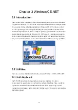
Страница 17: ...onment Windows CE NET contains everything you need to create a custom Windows CE based device that requires rich networking hard real time and a small footprint as well as rich multimedia and Web browsing capabilities 3 2 Utilities There are several useful utilities built in the standard Windows CE OS of NP 600S 3 2 1 Soft Keyboard The NP 600S is dedicated to the small sized operator interface It ...

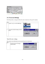
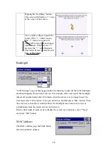
Страница 18: ...for users to make basic setting of the machine Step 1 Tap the cecp icon from Desktop 2 Launch the System Settings Control Panel Touch Screen settings The touch screen calibration can be executed from the Control Panel Step 1 Launch the System Settings Control Panel ...

Страница 19: ...n to turn off the LCD backlight and thus elongates the period of service For example if the user wants the backlight turned off automatically after 10 minutes when the device was no longer used The user must select 10 minutes in the put down box and then press OK button Then the screen save function is enabled Once the backlight was turned off events or perturbations from the touch screen can turn...

Страница 20: ...a as power failure When power is shutdown and cold boot the data in the Flash ROM area would be saved 3 2 4 Startup After the system boot up the startup execution function would automatically perform This function is useful for control system to do the initialization processes or some other programs Step1 Create startup directory in in IPSM Step2 Copy executable files or Shortcut to startup direct...

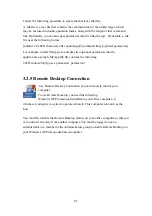
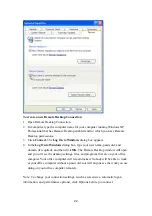
Страница 21: ...s into the application a sample MyApp lnk file contains the following 40 Windows MyApp exe parameter1 parameter2 3 2 5 Remote Desktop Connection Use Remote Desktop Connection you can remotely control your computer To use Remote Desktop you need the following Windows XP Professional installed on your office computer or whichever computer you plan to operate remotely This computer is known as the ho...

Страница 22: ...log box type your user name password and domain if required and then click OK The Remote Desktop window will open and you will see the desktop settings files and programs that are on your office computer Your office computer will remain locked Nobody will be able to work at your office computer without a password nor will anyone see the work you are doing on your office computer remotely Note To c...

Страница 23: ...p Connections 3 Find the default device name Change it to a unique one depending on the plan of individual LANs LAN90001 4 If the NP 600S is a node of a LAN with DHCP servers it is now available 5 If the NP 600S is a node of a LAN with fixed IP server please consult with MIS to get specific IP address Click Start Settings Control Panel Double click Network and Dial up Connections and update the IP...

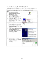
Страница 24: ...efore the Windows CE boot up don t connect the USB cable 3 Connect the USB client port of the NP 600S and the USB host port of the host PC by the USB client to USB host cable 4 When the Add New Hardware Wizard asks for the driver click Browse and select the file named wceusbsh inf under the USB driver directory 5 Follow the onscreen instructions to establish a partnership and synchronize your NP 6...

Страница 25: ...d with built in Windows CE operating system In real applications users need to execute various applications programs on it However unlike its other family the Windows CE is a hardware dependent operating system That is to say Windows CE application programs are only portable in the source code level Users must rebuild the runtime file for a different Windows CE platform even though the source code...

Отзывы: