


Page 15 of 48
Heatpipe Furnace Models 17702W, 17702P, 17702S (13
–
07/20)
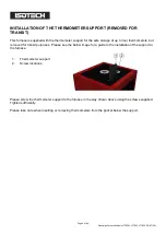
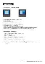
QUICK START
Locate the furnace in a suitable, level location. Leave a minimum of 150mm of space around and 500mm
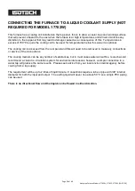
above the furnace for air circulation. Ensure there is a suitable water supply or circulation system for the
cooling of the furnace (see page 28) and power supply nearby.
Assemble the furnace as on page 29, ensure the coolant is connected as in on page 28 and the equipment
has a suitable electrical connection as on page 9. Connect the furnace to the electrical supply and power it
up.
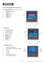
The Overtemperature controllers will power up and display the current temperature.
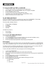
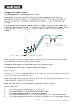
To power up the Heatpipe furnace you will need to enable the controller. To do this, press the SCROLL
button on the Overtemperature controller until Hi Alarm is displayed, using the up/down buttons enter a new
temperature for the overtemperature protection. Initially this can be quite a low value, say 500°C
*
, for test
purposes. Now press the SCROLL and PAGE buttons together, once to enter the new value and a second
time to reset the controller. On the second press the furnace will make a noise as the control circuit powers
up.
The furnace is now active and ready for use. On the controller, press the SCROLL button to highlight the
Setpoint box. Press again to adjust the value and select a suitable value, a value 20°C below the
overtemperature is suitable, using the up/down buttons. Enter the value by pressing the Scroll button. The
furnace will now rise in temperature to the selected value.
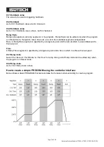
If the furnace has been in transit or not been used for several days then there may be an ingress of
moisture into the insulation and other ceramics, the furnace may need to be “dried out” by running at a low
value such as 400/450°C
**
for a period of several hours.
*
100°C for W version
**
150°C for W version


