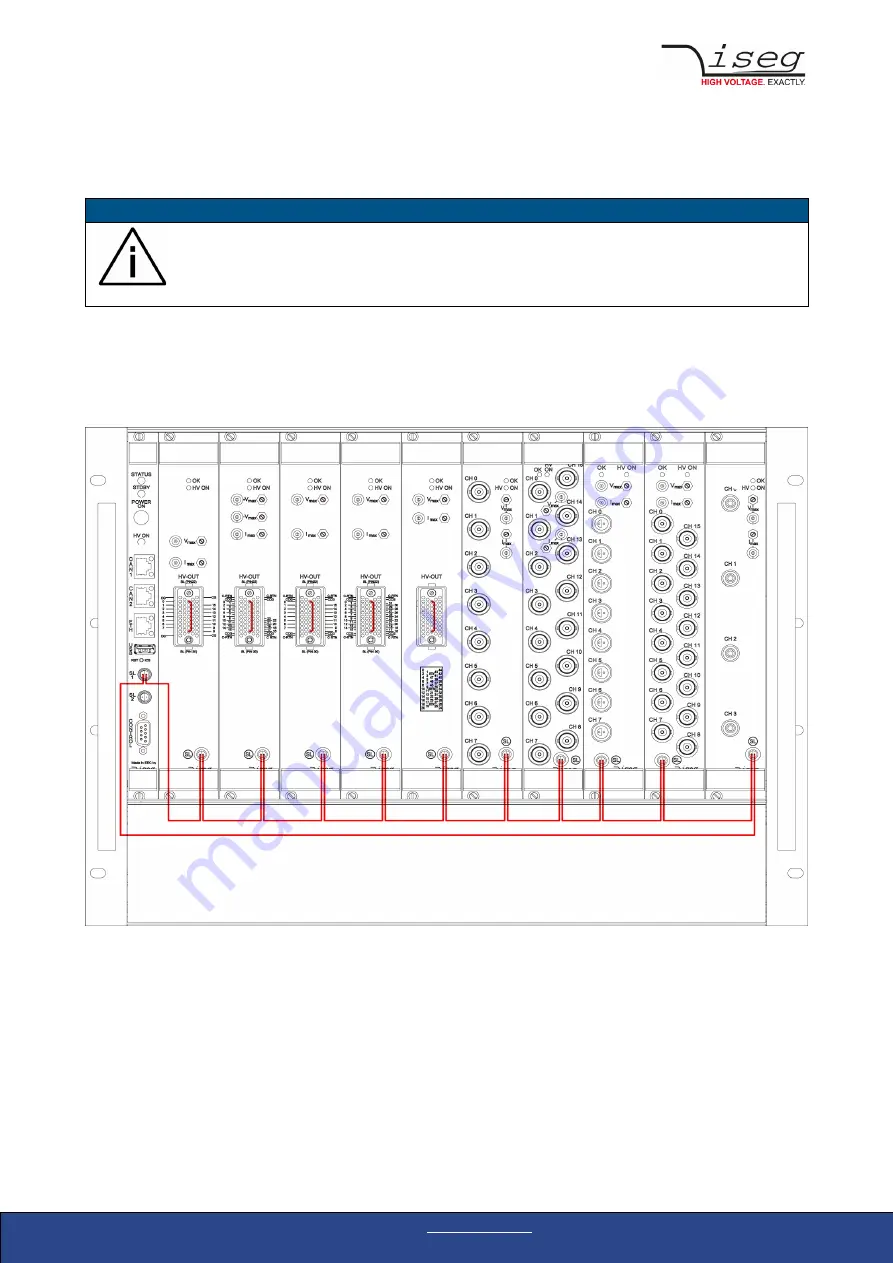
7.2. Safety-Loop connector
The SL1 and SL2 connectors serve as current source for the safety loop. The current flow through a safety loop enables the high
voltage generation within the modules. When the safety loop is interrupted, the high voltage generation stops immediately.
INFORMATION
INFORMATION
The safety loop feature has to be activated by removing a jumper on the backside of the high-voltage modules
also. See the specific module manual for more information. Check the compatibility with the devices used.
SL1
Potential-free current source (8 to 10 mA) to supply a safety loop for up to 10 modules. The safety loop is routed through the
modules SL connectors by a series connection. Start- and end point of the safety loop is SL1. For modules with a Redel connector,
the associated SL pins have to be bridged. Additional potential-free contacts to open the safety loop through external signals can
also be inserted.
Figure 4: Safety loop 1 - wiring example
SL2
A current source on crate GND potential for modules with option SLP (internal supplied safety loop). The SL2 connector pins can
be bridged by a short-circuit plug or an external potential-free switch. In this case the modules are supplied with the loop current
via the crate's backplane.
To enable a module its SL connector (and, if applicable, the SL pins on the Redel connector) must be bridged. All modules are
supplied with the loop current in parallel, i.e. opening the SL connector on a module will only deactivate this one module.
Crate Controller CC24/CC23 | Last change on: 14.04.2020 |
www.iseg-hv.com
16/44


