2.5.5.4 Status bar
Status bar includes cursor coordinate information in the drawing area (display rectangular and polar
coordinates simultaneously), and the color of the current editing area (protective field displays red, warning
field displays yellow).
When the cursor is moving in the drawing area, the coordinate information of status bar updates
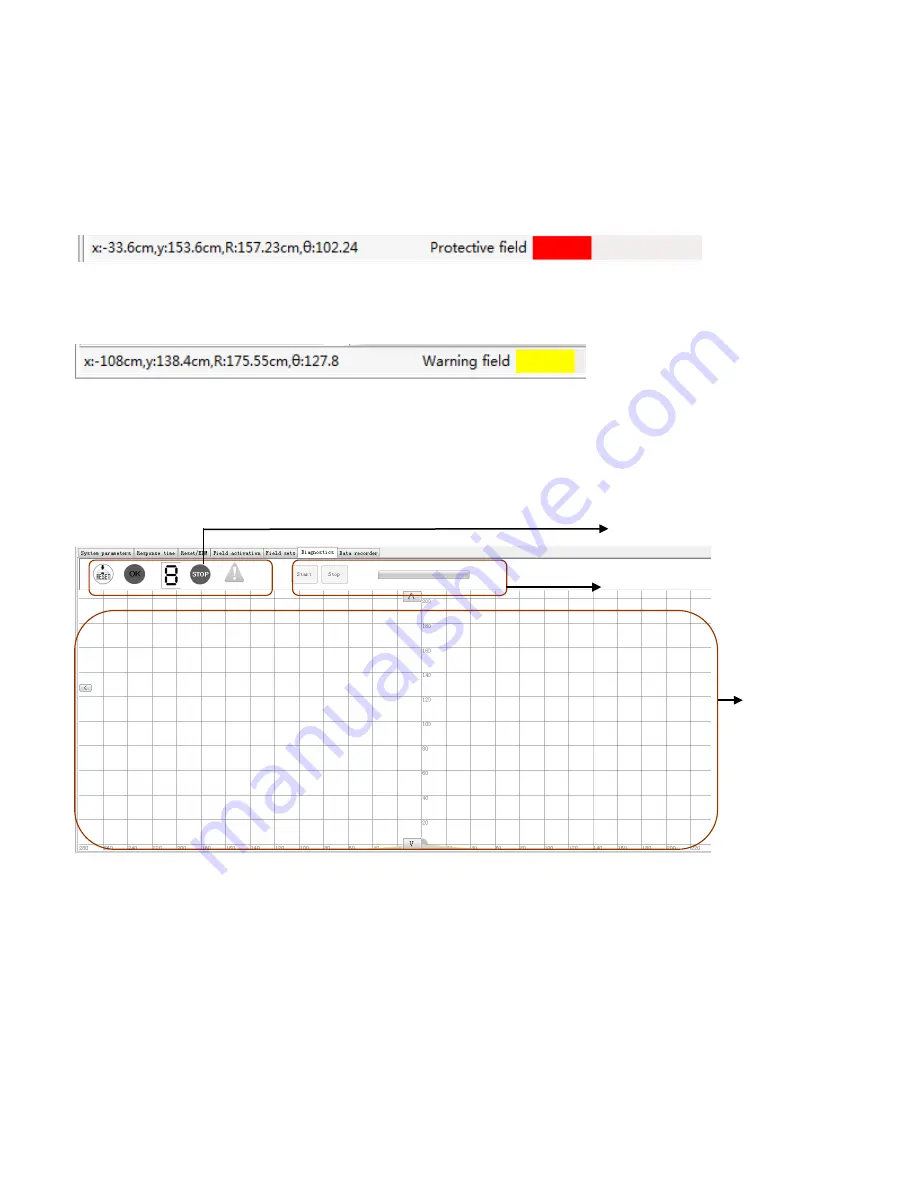
Click the icon to edit protective field, the status bar is displayed as shown in Fig.2.5.5.4.1.
Fig.2.5.5.4.1 Status display of protective field
Click the icon to edit warning field, the status bar is displayed as shown in Fig.2.5.5.4.2.
Fig.2.5.5.4.2 Status display of warning field
2.5.6 Diagnostics
The user can select the
[
Diagnostics
]
tab to monitor the scanner in real-time, displaying status of the
indicator window on the scanner, the outline of current field and the outline of the surrounding, as shown in
Fig.2.5.6.1.
Fig.2.5.6.1 Diagnostics tab
Canvas area: Showing the boundary outline, surrounding outline of the current protective field.
Start button: This will activate diagnosis function after the connection to a computer has been established.
The user can click the
[
Start ]
icon to read the configuration from the scanner and display the real-time
scanned floor plan on the canvas and the indicator status bar.
Stop button: Stop is available only after Start has been clicked. The user may click the
[
Stop
]
icon at any
time to halt the real time updating. Real-time updating can be restated at any time.
38
Display
zone
Start and stop button
Status indicator
Содержание LSPD
Страница 6: ...6 ...


