12
Ioline
Adjusting Blade Exposure and Force
Properly adjust blade exposure and force to achieve good cutting results.
Adjusting Blade Exposure:
1. Turn the Force knob clockwise to maximum. Set the Speed to 50% with
the keypad knob. The maximum force setting is adjustable in the Control
Center to 400 grams if required for thick materials. A maximum force of
200 grams is sufficient for most materials.
2. Check that the blade tip is barely visible when viewing the blade from the
side. This technique approaches the correct blade exposure from too little
with no chance of having too much (which could damage the blade).
3. Press the Start/Stop button on the front panel until the LED is red. Move
the carriage until the blade is near the right edge of the material.
4. Press the Test Cut key for one second. The signcutter will cut a test sign.
There will be no cutting if the initial foot adjustment was correct.
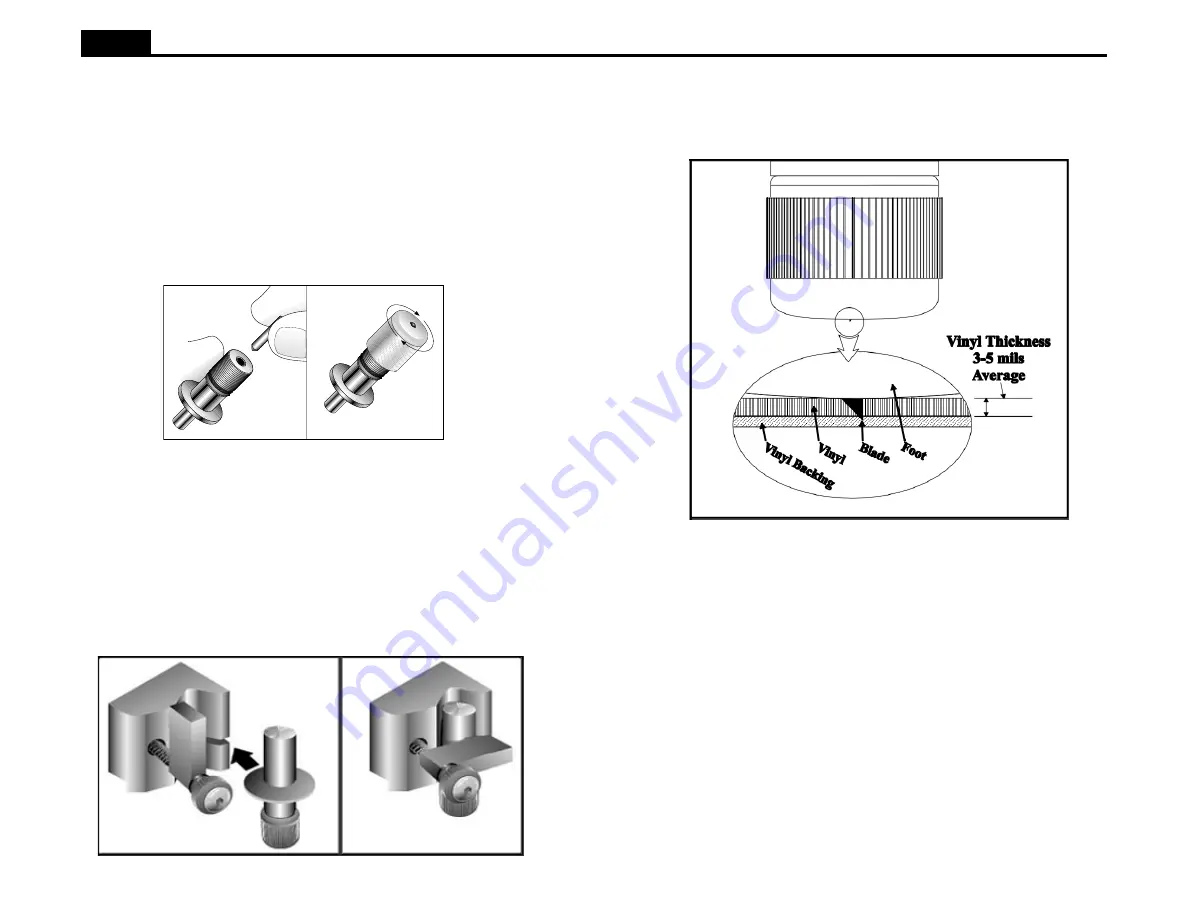
Figure 10. Proper blade exposure that lightly scores the backing.
Installing a Blade and the Blade Foot
Note: Using a hard surface to insert the blade may damage it.
A blade and a blade holder are included in the accessory kit. The blades are
sharp and brittle and the tips can chip or break. Be very careful when handling
the blades. To install the blade and blade foot in to the blade holder:
1. Remove the foot from the assembly by unscrewing it counterclockwise.
2. Slide the blade into the hole in the blade holder until it bottoms out. The
blade should spin freely.
3. Screw the foot onto the shank (clockwise). Stop before the blade emerges.
Installing a Blade Holder or Pen
1. Rotate the clamp screw until there is enough room to insert the blade
holder or pen. Make sure that the clamp is rotated up out of the way.
2. If using a blade holder or plotter pen, slip the flange into the slot in the
carriage jaw. If using a regular pen, position the tip 1/10 inch off of the
platen when the jaw is in the up position. The signcutter can hold any pen
with a maximum barrel diameter of 7/8” (22 mm).
3. Tighten the clamp screw until the blade or pen is secure.
Figure 9. Installing a Blade Holder in the Carriage Jaw.
Figures 8. Installing the Blade and the Blade Foot in the Holder.


