Note
: if the anti-masking function is active when the sensor is moving also, this could generate false alarms
since the environment change during movement could be detected as tampering.
l
Manual restart: the restart is triggered externally and only once the static object is removed from the
trajectory of the moving vehicle or moving part.
l
Application logic on PLC/control unit that permanently stops the moving part if multiple stops occur
immediately after the restart of the part. If the vehicle or the part stops very quickly after the restart, this
probably means that there is a static obstacle. Once the moving part is stopped, the sensor does not detect
the object anymore and therefore the part moves but it stops again as soon as it detects the object again.
5.6.5 Recommendations for positioning the sensor
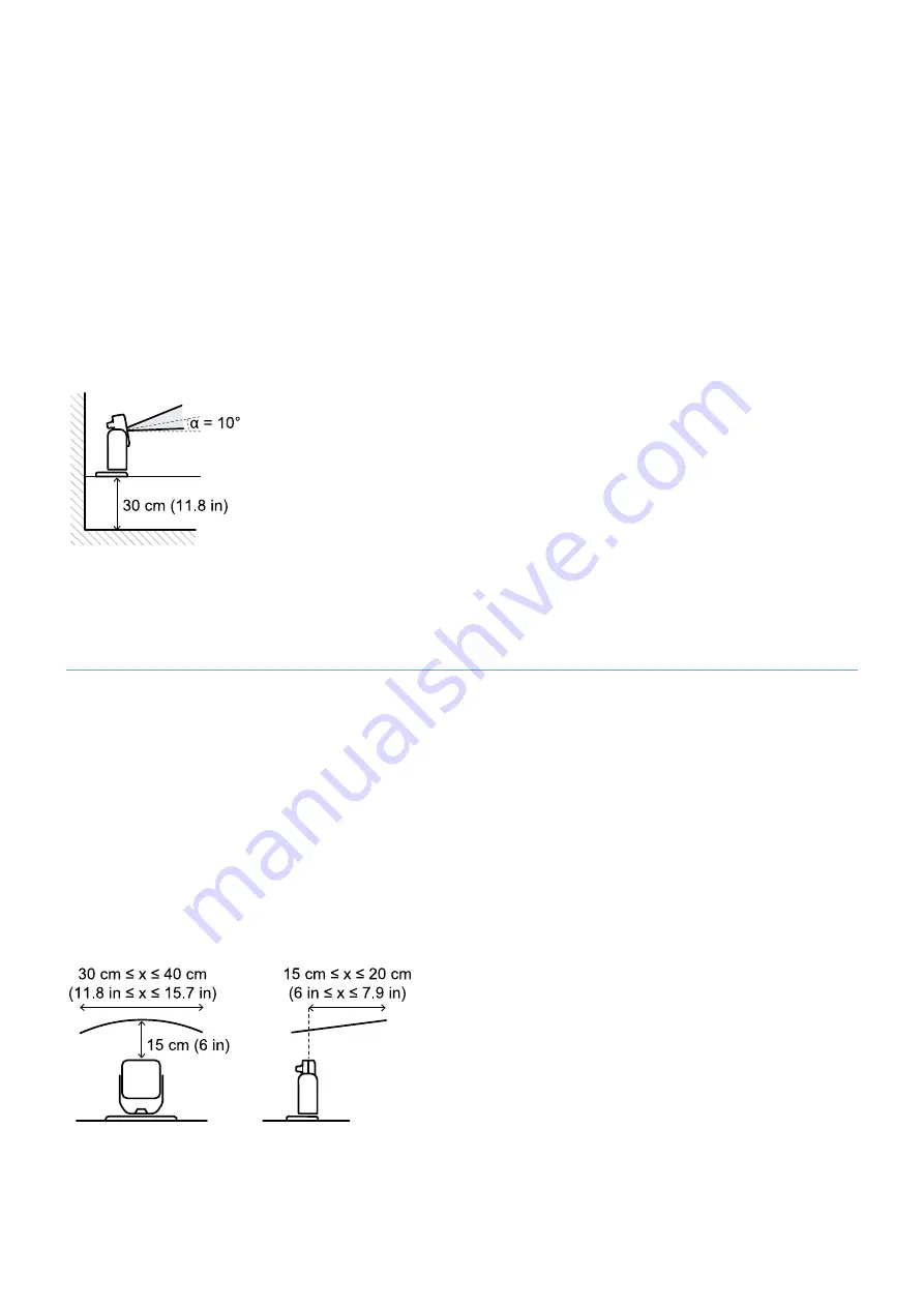
When the sensor is moving, the floor should be treated as a static object. The sensor must be positioned so that
the floor is excluded from the sensor's detection area.
Below are some recommendations for the sensor positioning:
l
as low as possible, but not below 30 cm (11.8 in) above the ground
l
with a suggested inclination of 10°
If the sensor is facing downwards, the detection distance and the inclination of the sensor needs to be adjusted
so that the floor is excluded from the detection field. Moreover, it is suggested that 30 cm (11.8 in) be left
between the end of the detection field and the floor, to avoid false alarms due to the tolerance area.
5.7 Outdoor installations
5.7.1 Position exposed to precipitation
If the sensor installation position might be exposed to precipitation that can cause undesired alarms, it is
recommended to take the following precautions:
l
make a cover to protect the sensor from rain, hail or snow
l
position the sensor so that it does not frame the ground where puddles might form
5.7.2 Recommendations for covering the sensor
Below are some recommendations for creating and installing a sensor cover:
l
height from sensor: 15 cm (6 in)
l
width: minimum 30 cm (11.8 in), maximum 40 cm (15.7 in)
l
protrusion from the sensor: minimum 15 cm (6 in), maximum 20 cm (7.9 in)
l
water outflow: at the sides or behind but not in front of the sensor (the cover should be arched and/or tilted
backwards)
5. Sensor position
SBV System Series | Instruction manual v1.2 DEC 2021| SAF-UM-SBVBus-en-v1.2 | © 2021 Inxpect SpA
49
Содержание SBV System Series
Страница 101: ......


