Inverter Drive CFW-08 Скачать руководство пользователя страница 14

Easy Start Guide

Page 13

This guide has been produced by The Inverter Drive Supermarket Ltd.
All content, including but not limited to graphics, text and procedures copyright

The Inverter

Drive Supermarket and must not be reproduced or altered without prior written permission.

©

13. How to configure “3-Wire” control with Run/Stop
pushbuttons and Forward/Reverse selection

The parameters described in Section 5 enable
Run/Stop operation via the red and green
buttons on the Inverter.

If this is unsuitable for the application, remote
switches can be used instead.

This section explains how to enable 3-wire
control with Run and Stop via pushbuttons and
Forward/Reverse via a selector switch.

Ensure the Inverter is in “Remote” mode
before continuing.

Parameter

Description

How to set

P000

Parameter Access

Set to

to allow parameters to be changed

5

P230

Remote Command Selection

Set to

to use the Inverter terminals (as opposed to keypad)

1

P263

Digital input 1 (T1) function

Set to

for 3-wire control “Start” on T1 (ignore E24 error, will clear when P264 is set)

14

P264

Digital input 2 (T2) function

Set to

for 3-wire control “Stop” on T2

14

P265

Digital input 3 (T3) function

Set to 1 for reset on T3 (or set to 1, 3, 6, 11, 12, 13 or 15 as required but no other values)

0

P266

Digital input 4 (T4) function

Set to

for forward/reverse selection on T4

0

13.1 Parameters to change for remote 3-wire control

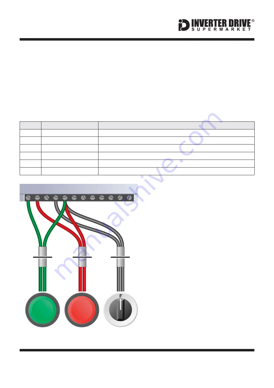
13.2 Connecting the Switches

A wiring diagram is shown in the illustration
opposite.

For “Run” and “Stop”, two suitable
pushbuttons should be installed. The “Run”
pushbutton should include a Normally Open
contact between terminals 5 (COM) and 1
(DI1) and the “Stop” a Normally Closed contact
between terminals 5 (COM) and 2 (DI2).
For “Forward/Reverse” a suitable 2 position
NO (

) switch should be installed

between terminals 5 (COM) and 4 (DI4).

A momentary connection between 5 (COM)
and 1 (DI1) will start the motor. It will continue
to run until the connection between 5 (COM)
and 2 (DI2) is broken.

Terminal 5 (COM) is a common

connection for terminals 1-4, 6 and 8 and has
no other function.

Normally Open

Note that the Forward/Reverse switch only
selects the direction of rotation - it will not start
or stop the motor. If the application only
requires the motor to turn in one direction, the
Forward/Reverse switch can be omitted.

1

2

1

4

Pushbutton

Normally Open

“Run”

R

Pushbutton

Normally Closed

“Stop”

Switch, 2 Position

Normally Open

“Forward / Reverse”

1

3

WEG CFW-08 Series Inverter

1 2 3 4 5 6 7 8 9 10 11 12

COM

DI1 DI2

DI4

1

4

3

2

Содержание CFW-08

Страница 1: ...It should not be used as a replacement for the manual issued by the manufacturer Issue 2 20140223 This product is not a safety device All safety considerations including but not limited to Emergency S...

Страница 2: ...otor Connections Star and Delta Parameters Overview Parameters to set before use How to Operate the Inverter from the keypad How to switch from Local keypad control to Remote terminal control and back...

Страница 3: ...rame size 2 rating 1 5kW The terminal layout for other sizes and the Wash model is similar The order of the three phases determines the direction the motor turns Important Use screened SY cable betwee...

Страница 4: ...odel is similar The order of the three motor phases determines the direction the motor turns The order of the three power phases is unimportant Important Use screened SY cable between the Inverter and...

Страница 5: ...sometimes known as two at one side Only two links are required for Star Double up the links if changing from Delta to allow the motor to be changed back in future The order of the three phases determ...

Страница 6: ...Hz 50 00 P404 Rated Motor Power Refer to P404 table in manual and set to match motor nameplate eg for 1 5 kW 6 P407 Rated Motor Power Factor Set to match motor if known eg look for cos 0 74 The Invert...

Страница 7: ...tter P followed by a three digit number Typically this is P000 as shown in the illustration opposite 6 2 Find the Parameter to change Use the up and down keys to find the required parameter In this ex...

Страница 8: ...ed for a standard 50Hz Induction Motor Leave the display showing the speed in Hz See section 6 to learn how to set a parameter value 7 3 Start the motor and change direction Press the green button to...

Страница 9: ...pad control When the green indicator lamp next to the Loc Rem button is illuminated the Inverter is in Local mode When in Local mode the motor can be controlled using the integrated keypad The default...

Страница 10: ...or builds a model of the motor it is controlling This is achieved by a tuning run during which the Inverter operates for approx 2 minutes to gather the necessary motor data Note Sensorless Vector is n...

Страница 11: ...ter can be used instead This provides the benefit of allowing motor speed to be controlled from a more convenient location such as a cabinet door if the CFW 08 is cabinet mounted or on the machine its...

Страница 12: ...een terminals 1 DI1 and 5 COM the motor will run forward When terminals 2 DI2 and 5 COM are connected the motor will run in reverse Care should be taken to ensure that terminals 1 DI1 and 2 DI2 cannot...

Страница 13: ...eneral Enable link is required between terminals 1 and 5 Note that the Forward Reverse switch only selects the direction of rotation it will not start or stop the motor If the application only require...

Страница 14: ...nput 3 T3 function Set to 1 for reset on T3 or set to 1 3 6 11 12 13 or 15 as required but no other values 0 P266 Digital input 4 T4 function Set to for forward reverse selection on T4 0 13 1 Paramete...

Страница 15: ...Connect the brake resistor to the BR and UD Terminals on the Inverter The order of the connections is unimportant The braking resistor may get hot during operation Ensure that it is mounted in a suit...

Страница 16: ...00 to 5 Press the PROG button again to select the parameter value Use the up and down keys to set this value to 5 Press PROG again to save The display will return to P000 Note setting P000 to 5 allows...

Отзывы: