


38
| Optidrive ODP-2 Solar Pump User Guide |
Version 2.04
www.invertekdrives.com
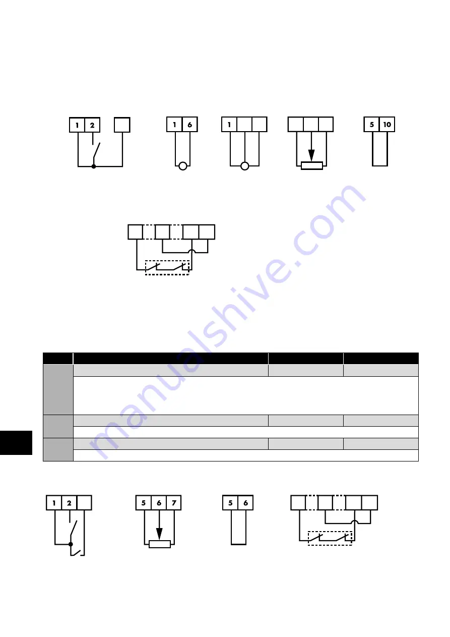
6.2.9. Minimum control wiring requirements when using an irradiance sensor
The P2 Solar Pump Drive is a very flexible product which can be controlled in a number of ways. In order to operate the drive as
detailed in section
, the drive will need the STO circuit to be closed (see section
and a drive enable provided to Digital Input 1 as shown below. Please note that if the STO function is not going to be used in the
application, the wiring is still required and a link will be needed between terminals T1-T12 and T9-T13.
Minimum Control wiring required for using an irradiance sensor
Start/Stop
Irradiance Sensor
Speed Reference
4
Or
6
7
5 10 9
Or
Link T1 to T2 to start and open to stop.
Link T1 to T4 to change the speed
source from AI1 to AI2
Loop-powered
transducer
3-wire
transducer
Potentiometer
Maximum
possible
Mandatory Hardware Enable
1
9
12 13
The STO inputs can be used as a high integrity means of preventing torque
being applied on the motor – section
. If this function
is not required, the terminals must be linked as illustrated.
6.2.10. Operation with a Float-switch
Some applications require the start/stop of the pump to be controlled by a float switch. In some instances, waves on the water surface
can cause unwanted start/stop commands to the drive. To overcome the potential issue caused by these waves, a mode has been
created in the drive where a delay can be applied to the start and to the stop command. This can be configured as shown below:
Par.
Description
Default
Typical
P1-13
Digital Input Function Select
1
-
For use with a float switch, set this parameter to the required value:
15: Float switch with normally open contact (close to run)
16: Float switch with normally closed contact (open to run)
The delay start and delay stop are configured in P6-06 and P6-07.
P6-06
Delay Start Time
0s
10s
This delay will be applied to all RUN commands for the drive.
P6-07
Low Power Standby Restart delay
0s
10s
This delay will be applied to all STOP commands for the drive with the exception of the STO.
Minimum Control wiring required for use with a float switch
Start/Stop
Speed Reference
Mandatory Hardware Enable
3
Or
1
9
12 13
T1 - T2 – Drive Enable
T1 - T3 – Run command
from Float Switch
Potentiometer
Maximum
possible
The STO inputs can be used as a high
integrity means of preventing torque being
applied on the motor – section
. If this function is not required, the
terminals must be linked as illustrated.
6
Quick Star
t Pr
ocedure