29
OPERATION AND SET-UP ON THE CONTROLLER
inVENTer Connect controller platform | Operating instructions
3.4 Selecting ventilation zones / Showing the status of ventilation zones
After component pairing, all paired components are assigned to ventilation zone 1. The controller
automatically starts with the factory settings (default profile) and displays the status of ventilation
zone 1.
If additional ventilation zones (max. 4) have been set up (
4: Operation and set-up with the app)
and each newly set up ventilation zone is assigned a corresponding profile, the status information
can also be displayed on the display screen.
After a defined period (approx. 3 minutes), the controller switches the view so that the status of
ventilation zone 1 is displayed again.
Requirements:
• Up to a maximum of 4 zones are set up using the
app.
►
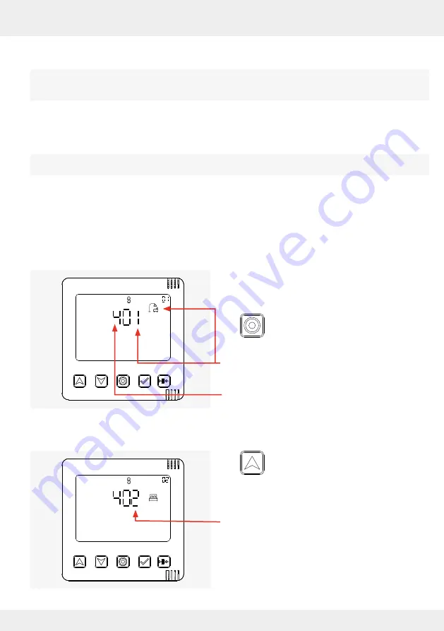
Press the mode key. The first defined
ventilation zone (ventilation zone 1)
appears with its profile icon.
Ventilation zone 1 and the corresponding profile
icon are displayed.
The display screen shows the total number of pos-
sible ventilation zones.
►
Use the up arrow key to navigate through
the ventilation zones until the desired
ventilation zone appears on the display
screen.
The next ventilation zone (ventilation zone 2) and
the corresponding profile icon are displayed.
The status of the ventilation zones is displayed directly by the controller (description below) or can
be viewed using the app (
4: Operation and set-up with the app).
Additional ventilation zones can only be set up via the "inVENTer-Mobile" app.


