background image


USER’S MANUAL

UG074

Rev.2.00

Nov 14, 2018

ISL9238EVAL1Z

Evaluation Board User Guide

UG074 Rev.2.00

Page 1 of 17

Nov 14, 2018

Description

The 

ISL9238

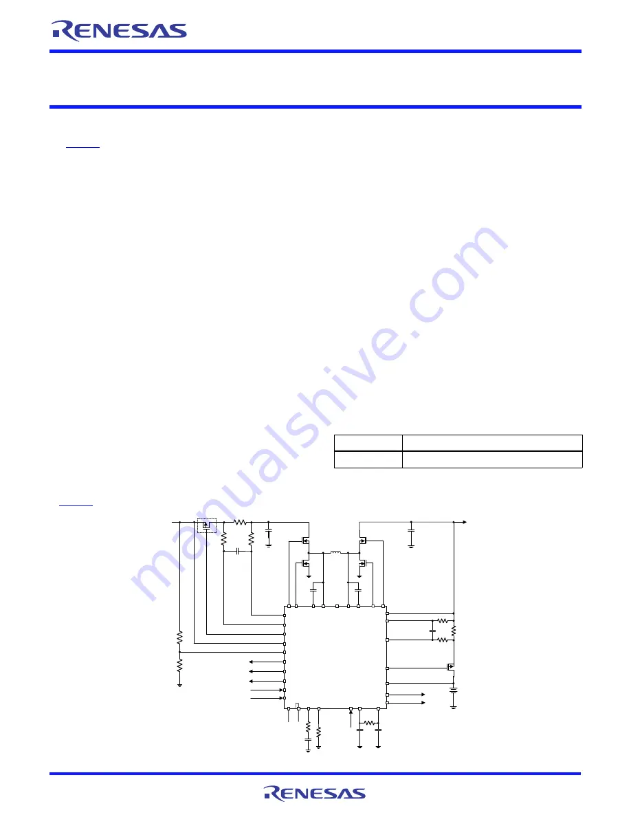
 is a buck-boost Narrow Output Voltage DC (NVDC) 

charger that uses the Renesas advanced R3™ Technology to 
provide high light-load efficiency, fast transient response, and 
seamless DCM/CCM transitions for a variety of mobile and 
industrial applications.

In Charge mode, the ISL9238 takes input power from a wide 
range (4V to 20V) of DC power sources (conventional AC/DC 
charger adapters, USB PD ports, travel adapters, etc.) and 
safely charges battery packs with up to four cells in a series 
configuration.

The ISL9238 has an On-the-Go (OTG) function for 2- and 4-cell 
battery applications. When the OTG function is enabled, the 
ISL9238 operates in Reverse Buck mode to provide 5V at the 
USB port.

The ISL9238 provides serial communication with SMBus/I

2

that allows programming of critical parameters to deliver a 
customized solution. The programmable parameters include, 
but are not limited to: adapter current limit, charger current 
limit, system voltage setting, and trickle charging current limit.

The ISL9238EVAL1Z evaluation board demonstrates the 
performance of the ISL9238. The default value numbers of the 
battery in series, switching frequency, and the adapter current 
limit charging function can be programmed by the resistor 
from the PROG pin to GND. The values also can be set by 
SMBus.

Related Literature

For a full list of related documents, refer to our website:

ISL9238

 datasheet

Key Features

• Buck-boost NVDC charger for 1-, 2-, 3-, 4-cell Li-ion batteries
• End of Charge (EOC) option
• System power monitor PSYS output, IMVP-8 compliant
• PROCHOT# open-drain output, IMVP-8 compliant
• Allows trickle charging of depleted battery
• Optional ASGATE FET control
• Ideal diode control in Turbo mode
• Reverse buck, boost, and buck-boost operation from battery
• Two-level adapter current limit available
• Battery Ship mode option
• SMBus and auto-increment I

2

C compatible

Specifications

• V

IN 

= 3.8V to 24V (no dead zone)

• V

OUT

 = 2.5V to 12.6V

• MAX  I

charge

 up to 6A

• f

SW 

= 1MHz maximum

Ordering Information

PART NUMBER

DESCRIPTION

ISL9238EVAL1Z

ISL9238 buck-boost charger evaluation board

FIGURE 1. BLOCK DIAGRAM

ISL9238

B

OOT

1

P

HAS

E

1

UG

AT

E

1

V

DDP

LG

A

T

E

1

LG

A

T

E

2

UG

AT

E

2

P

HAS

E

2

B

OOT

2

SC

L

SD

A

VBAT

CSOP

CSON

DC

IN

VD

D

CO

M

P

PSYS

BGATE

ASGATE

PROCHOT#

ACIN

ACOK

GND

CSIP

CSIN

AMON/BMON

BATGONE

VADP

VBAT

VSYS

PR

O

G

VSYS

OTGPG/CMOUT

ADP

OTGEN/CMIN

Q

1

Q

2

Q

4

Q

3

R

s1

Rs2

L1

Optional

Содержание ISL9238EVAL1Z

Страница 1: ...ISL9238EVAL1Z evaluation board demonstrates the performance of the ISL9238 The default value numbers of the battery in series switching frequency and the adapter current limit charging function can be programmed by the resistor from the PROG pin to GND The values also can be set by SMBus Related Literature For a full list of related documents refer to our website ISL9238 datasheet Key Features Buc...

Страница 2: ...ged through the SMBus control registers in the Renesas GUI shown in Figure 2 on page 3 The three LEDs indicate the ACOK PROCHOT and OTGPG CMOUT status respectively For more details about the functions of these three pins refer to the ISL9238 datasheet Complete the following steps to evaluate the ISL9238 key functions including system voltage regulation input current limit regulation Charging mode ...

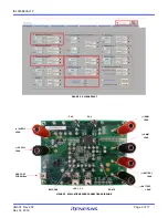
Страница 3: ...3 of 17 Nov 14 2018 ISL9238EVAL1Z FIGURE 2 GUI SNAPSHOT FIGURE 3 EVALUATION BOARD CONNECTION GUIDELINE SUPPLY SUPPLY USB PORT FOR SMBus PH1 PH2 DMM DMM BATTERY BATTERY BGATE LED 1 2 3 BATGONE LEAD LEAD LEAD LEAD LEAD LEAD ...

Страница 4: ...imit value especially for a small VIN input Trickle Charging Mode 1 Complete Steps 1 through 6 in Charging Mode without any changes 2 Decrease the battery emulator voltage and monitor the battery charging current As long as the battery emulator voltage is less than 5 2V lower than SystemMinVoltage the battery enters trickle Charging mode and the charge current decreases to 0 26A The trickle charge...

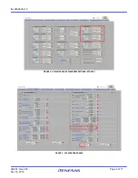
Страница 5: ...UG074 Rev 2 00 Page 5 of 17 Nov 14 2018 ISL9238EVAL1Z FIGURE 4 OTGVOLTAGE AND OTGCURRENT SETTINGS IN THE GUI FIGURE 5 OTG FUNCTION ENABLE ...

Страница 6: ...3 S 73 5 1 73 B B X 73 73 5 5 X X 5 5 X 4 6 6 1 6 6 6 5 5 5 73 56 8 6 1 1 9 27 1 0 1 6 6 352 27 2 7 21 352 27 3 0287 203 021 021 36 6 9 7 7 3 6 7 621 623 96 6 227 8 7 3 6 7 9 3 3 6 3 6 1 6 7 227 8 7 3 1 73 73 5 73 3 X 73 73 X X 73 73 73 3 X 73 6 73 5 5 73 73 73 X 73 X 73 1 73 X X 5 5 B B 73 5 X 73 X 73 1 4 1 X 4 6 1 6 6 6 73 X X 3 73 X 5 Q 73 4 6 1 6 6 6 4 1 73 X 5 73 B B X 73 5 4 6 6 1 6 6 6 1 1 ...

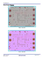
Страница 7: ...UG074 Rev 2 00 Page 7 of 17 Nov 14 2018 ISL9238EVAL1Z FIGURE 7 TOP OF BOARD FIGURE 8 BOTTOM OF BOARD ...

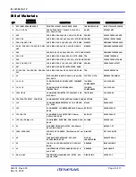
Страница 8: ...R ROHS TDK C2012X5R1E106K 1 L1 PWR CHOKE COIL SMD 6 95x6 6 2 2µH 10A 20 ROHS CYNTEC CO LTD PIMB063T 2R2MS 01 3 J1 J3 J5 CONN GEN BIND POST INSUL RED THMBNUT GND JOHNSON COMPONENTS 111 0702 001 3 J2 J4 J6 CONN GEN BIND POST INSUL BLK THMBNUT GND JOHNSON COMPONENTS 111 0703 001 2 TP13 TP14 CONN SCOPE PROBE TEST PT COMPACT PCB MNT ROHS TEKTRONIX 131 4353 00 51 TP1 TP12 TP15 TP37 TP43 TP58 CONN MINI T...

Страница 9: ...603 5 62k 1 10W 1 TF ROHS PANASONIC ERJ 3EKF5621V 1 R25 RES SMD 0603 6 04k 1 10W 1 TF ROHS VENKEL CR0603 10W 6041FT 1 R27 RES SMD 0603 698Ω 1 10W 1 TF ROHS PANASONIC ERJ 3EKF6980V 1 RS2 RES CURR SENSE SMD 1206 0 01Ω 1W 1 75ppm ROHS VISHAY DALE WSLP1206R0100FEA 1 RS1 RES CURR SENSE SMD 1206 0 02Ω 1W 1 75ppm ROHS VISHAY DALE WSLP1206R0200FEA 2 SW1 SW2 SWITCH TOGGLE SMD 6PIN SPDT 2POS ON NONE ON ROHS...

Страница 10: ...ficient width Do not allow any sensitive analog signal traces to cross over or get close to this pin Renesas recommends routing the PHASE2 trace to the high side MOSFET source pin instead of general copper Place the IC close to the switching MOSFET s gate terminals and keep the gate drive signal traces short for a clean MOSFET drive The IC can be placed on the opposite side of the switching MOSFET...

Страница 11: ...area the two terminals of the adapter current sensing resistor to the IC Place the differential mode and common mode RC filter components in the general proximity of the controller Route the current sensing traces through vias to connect the center of the pads or route the traces into the pads from the inside of the current sensing resistor The following drawings show the two preferred ways of rou...

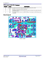
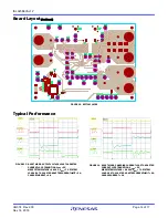
Страница 12: ...ecial consideration 31 VBAT Place the optional RC filter in the general proximity of the controller Run a dedicated trace from the battery positive connection point to the IC 32 BGATE Use a sufficiently wide trace from the IC to the BGATE MOSFET gate Place the capacitor from BGATE to ground close to the MOSFET PCB Layout Guidelines Continued PIN NUMBER PIN NAME LAYOUT GUIDELINES Board Layout FIGUR...

Страница 13: ...UG074 Rev 2 00 Page 13 of 17 Nov 14 2018 ISL9238EVAL1Z FIGURE 10 INNER LAYER 1 FIGURE 11 INNER LAYER 2 Board Layout Continued ...

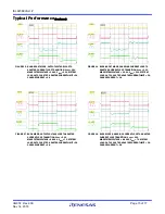
Страница 14: ...PUT VOLTAGE LOOP TO ADAPTER CURRENT LOOP TRANSITION VADP 5V MAXSYSTEMVOLTAGE 8 496V VBAT 7V SYSTEM LOAD 0 5A TO 10A STEP ADAPTERCURRENTLIMIT 3A CHARGECURRENT 0A FIGURE 14 BOOST MODE CHARGING CURRENT LOOP TO ADAPTER CURRENT LOOP TRANSITION VADP 5V MAXSYSTEMVOLTAGE 8 496V VBAT 7V SYSTEM LOAD 0 5A TO 10A STEP ADAPTERCURRENTLIMIT 3A CHARGECURRENT 1A ...

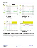
Страница 15: ... TRANSITION VADP 12V MAXSYSTEMVOLTAGE 12 6V VBAT 11V SYSTEM LOAD 1A TO 10A STEP ADAPTERCURRENTLIMIT 3A CHARGECURRENT 1A FIGURE 17 BUCK MODE OUTPUT VOLTAGE LOOP TO ADAPTER CURRENT LOOP TRANSITION VADP 20V MAXSYSTEMVOLTAGE 8 496V VBAT 7V SYSTEM LOAD 2A TO 10A STEP ADAPTERCURRENTLIMIT 3A CHARGECURRENT 0A FIGURE 18 BUCK MODE CHARGING CURRENT LOOP TO ADAPTER CURRENT LOOP TRANSITION VADP 20V MAXSYSTEMVO...

Страница 16: ...SYSTEMVOLTAGE 8 496V VBAT 7V VINDAC 4 5V SYSTEM LOAD 0 5A TO 10A STEP CHARGECURRENT 1A FIGURE 21 OTG MODE ENABLE OTG ENABLE 150ms DEBOUNCE TIME FIGURE 22 OTG MODE 0 5A TO 2A TRANSIENT LOAD OTG VOLTAGE 5 12V Typical Performance Continued Revision History The revision history provided is for informational purposes only and is believed to be accurate but not warranted Please visit our website to make...

Страница 17: ...ment Renesas Electronics products are not intended or authorized for use in products or systems that may pose a direct threat to human life or bodily injury artificial life support devices or systems surgical implantations etc or may cause serious property damage space system undersea repeaters nuclear power control systems aircraft control systems key plant systems military equipment etc Renesas ...

Страница 18: ...Mouser Electronics Authorized Distributor Click to View Pricing Inventory Delivery Lifecycle Information Renesas Electronics ISL9238EVAL1Z ...

Отзывы: