Important Safeguards
Warning
•
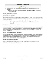
To Reduce The Risk Associated With Mechanical, Pneumatic, and Electrical
Hazards:
a. Allow Only Properly Trained And Qualified Personnel To Operate And Service
This Equipment.
Operator Skill Level Descriptions
Skill “A”: Machine Operator
This Operator Is Trained To Use The Machine With The Machine Controls, To Feed Cases Into The
Machine, Make Adjustment For Different Case Sizes, To Change The Tape And To Start, Stop, And
To Re-Start Production
Important: The Area Supervisor Must Ensure That The Operator Has Been
Properly Trained On All Machine Functions Before Operating The
Machine.
Skill “B” Mechanical Maintenance Technician
This Technician Is Trained To Use The Machine As The Machine Operator And In Addition Is Able To
Work With The Safety Protection Disconnected, To Check And Adjust Mechanical Components, To
Perform Maintenance Operations And Repair The Machine. He Is Not Allowed To Work On Live
Electrical Components
Skill “C” Electrical Maintenance Technician
This Technician Is Trained To Use The Machine As The Machine Operator And In Addition Is Able To
Work With The Safety Protection Disconnected, To Check And Adjust Mechanical Components, To
Perform Maintenance Operations And Repair The Machine. He Is Allowed To Work On Live
Electrical Panels, Terminal Blocks And Control Equipment.
Skill “D” Manufacturers Technician
Skilled Technician Sent By The Manufacturer Or Its Agent To Perform Complex Repairs Or
Modifications, When Agreed With The Customer
16
UDM10008
UDM780-04
UA262024 SB Manual
UM095TW / UM595TW
Содержание IPG UA 262024 SB
Страница 31: ...31 Figure 18 Ski adjustment UDM10008 UDM780 04 UA262024 SB Manual UM095TW UM595TW SET UP PROCEDURES...
Страница 35: ...35 Figure 22 Install new belt UDM10008 UDM780 04 UA262024 SB Manual UM095TW UM595TW OPERATING INSTRUCTIONS...
Страница 40: ...4 7 2 3 5 10 9 11 12 13 15 14 8 6 19 17 16 18 1 BASE ASSEMBLY USM6104 A 1...
Страница 42: ...4 19 13 5 10 12 18 3 8 9 1 6 22 7 2 17 16 15 14 20 BASE SUB ASSEMBLY UAM0352 A 3...
Страница 46: ...A 7 LEG ASSEMBLY UAM0275 7 3 4 5 8 9 10 2 1 6 7 8 9 10...
Страница 48: ...A 9 GATE ASSEMBLY USM6110 2 4 3 1 8 6 7 5...
Страница 54: ...2 8 16 3 19 14 5 6 10 7 17 4 11 12 13 1 9 11 12 15 USM6100 A 15...
Страница 56: ...2 10 4 3 5 9 13 12 17 8 7 14 15 16 1 11 14 15 18 6 USM6101 A 17...
Страница 60: ...A 21 LOCKING MECANSM USM0391 6 1 5 7 2 3 4 8...
Страница 62: ...A 23 COMPRESSION GUIDE USM6109 2 5 1 4 3 6 7...
Страница 64: ...A 25 KNOB CW 5mm PIN UAM0288 4 5 3 2 1...
Страница 66: ...1 9 22 24 10 11 20 21 29 32 20 6 28 4 27 2 13 14 3 8 5 16 17 7 23 12 26 15 33 18 25 31 30 19 A 27 USM7077...
Страница 75: ...A 36 ELECTRIC CONTROLS 2 1 4 8 3 6 5 7...
Страница 79: ...A 40 AIR TO COLUMN ASSEMBLY 3 4 5 1 1 7 6 1 2...
Страница 81: ...A 42 STOP START BOX UAM1084 STOP START BOX 5 4 7 1 10 8 2 9 3 6...
Страница 83: ...A 44 ELECTRIC BOX INSTALLED USM0808 DRIVE SECTION MOTORS 3 2 1 4 8 7 6 9 6 7 10 13 11 12 4 5 13...
Страница 87: ...A 48 SECOND E STOP INSTALLED OPTIONAL UM9003 1 3 4 7 5 6 2...
Страница 89: ...A 50 SECOND E STOP BOX ASSEMBLY OPTIONAL USM8075 2 3 1 5 4...
Страница 92: ...A 53 5 60 psi 3 5 PILOT 4mm TUBE AIR 8mm TUBE 3 KICKER GATE PNEUMATIC DIAGRAM...

