background image

Operation

Exhaust Diesel Particulate Filter Regeneration

This vehicle is equipped with a Diesel Particulate Filter
(DPF) to meet 2010 emissions requirements. The DPF traps
exhaust particulate matter generated by normal engine usage.
Periodically, the engine control system will perform a “cleaning”
of the filter, known as Normal Regeneration. This process is
transparent to the operator and occurs during normal vehicle
operation.

In some cases the engine control system is unable to manage
soot levels in the DPF through Normal Regeneration. When
this occurs the DPF indicator will illuminate solid YELLOW on
the instrument panel gauge cluster advising that action must be
taken. At this time the vehicle should then be driven at highway
speeds, or pulled over to perform a Parked Regeneration (See
Parked Regeneration Procedure).

If no action is taken the

DPF indicator will begin to flash indicating that the filter is full.
The vehicle should then be pulled safely off the roadway and
a Parked Regeneration should be performed. If the vehicle is
driven beyond the initial two warning stages, a loss of engine
performance (de-rate) will occur.

Ignoring the need for a

Parked Regeneration, when required, can result in a warning for
excessive exhaust temperatures, and a requirement to shut the
engine off and not restart it until the DPF has been serviced by
a technician. It is important to perform a Parked Regeneration
when required. Failure to do so could be mission disabling and
result in the vehicle being towed.

See the following information for a detailed explanation of DPF
indicators and the corresponding procedures that must be
followed.

WARNING

Failure to perform a Parked Regeneration when
exhaust filter indicator is ON will cause the engine
to lose power and eventually shutdown.

When performing Parked Regeneration, make
certain vehicle is safely off of the roadway
and exhaust pipe is away from people, or any
flammable materials or structures.

Failure to follow these instructions may result in
a loss of engine power, vehicle speed, increased
exhaust

temperatures,

and

may

cause

an

accident or fire resulting in property damage,
personal injury, or death.

There will be three levels of indication that the vehicle’s exhaust
filter is accumulating soot and needs to be cleaned, each with
an increasing urgency for action.

NOTE: A Level 1 indication may disappear or a Level 2 may
revert to a Level 1, if the vehicle is driven on highway at
highway speeds for an extended period. This process of auto
regeneration of the exhaust filter is activated when the engine
load is increased as a result of highway driving at highway
speeds.

If the DPF indicator does not reduce in level or

disappear, a Parked Regeneration must be performed.

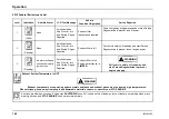
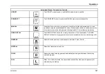
NOTE: The following table is a typical representation of 2010
DPF emissions procedures (See visor for vehicle federal
emissions label).

3878859R2

139

Содержание ProStar+ Eagle Series.

Страница 1: ... may subject that person or entity to criminal penalties Proposition 65 Warning Diesel engine exhaust and some of its constituents are known to the State of California to cause cancer birth defects and other reproductive harm Battery posts terminals and related accessories contain lead and lead compounds chemicals known to the State of California to cause cancer and reproductive harm Wash hands af...

Страница 2: ...1488 Warrenville Illinois 60555 630 753 5900 NORTHEAST Navistar Inc Cherry Tree Corporate Center 535 Route 38 East Suite 300 Cherry Hill New Jersey 08002 856 486 2300 SOUTHEAST Navistar Inc 2400 Commerce Avenue Building 1100 Suite 100 Duluth Georgia 30096 678 584 2700 SOUTHWEST Navistar Inc 2595 Dallas Parkway Suite 203 Frisco Texas 75034 972 377 1200 WEST Navistar Inc 3017 Douglas Boulevard Suite...

Страница 3: ...or by contacting your local International dealer It is the policy of Navistar Inc to improve its products whenever it is possible and practical to do so We reserve the right to make changes or add improvements at any time without incurring any obligation to make such changes on products sold previously Operator s Manual ProStar Series Operator s Manual Form No 3878859R2 2010 Navistar Inc All right...

Страница 4: ...Operator s Manual ProStar Series Printed in the United States of America 3878859R2 ...

Страница 5: ...ailable Models 9 Vehicle Identification 12 Vehicle Identification Number VIN 12 Feature Codes 12 Engine Serial Number 13 Line Set Ticket 13 Exterior Components 14 Cab Entry and Exit 18 Hood 18 Raising the Hood 18 Lowering the Hood 19 Tilt Away Bumper 19 Lowering the Tilt Away Bumper 20 Raising the Tilt Away Bumper 20 Luggage Box Access 21 Driver and Passenger Side 21 Chassis Skirts 21 Removal 21 I...

Страница 6: ...Lights On With Wipers 75 Park Lights 75 Panel Lighting 75 Dome Lighting 76 Courtesy Lights 76 Steering Wheel Controls 77 Cruise Control 78 Steering Column and Switches 78 Center Dash Panel Wing Panel 81 Gauges 82 Switches 82 Climate Control 86 Air Conditioning 88 Dehumidification 89 Electronic Vehicle Monitoring 89 Base Display 89 Premium Display 89 SmartWave Display 89 Door and Window Controls 90...

Страница 7: ...Information 106 Entering The Upper Bunk 107 Exiting The Upper Bunk 108 Cabinets Storage 109 General Information 109 Cabinets 110 Refrigerator Cabinet 110 Horizontal Refrigerator 111 Dresser Cabinet 111 Tower Wardrobe Cabinet 112 Rear Wardrobe Cabinet 113 Airline Cabinets 114 Convenience Features 115 General Information 115 Sleeper Curtain 115 Television Mount 115 Power Inverter 115 Power Sockets 1...

Страница 8: ...ooling System 135 Engine Oil 136 Engine Performance Problems 136 Fuel 137 Ultra Low Sulfur Diesel Fuel Requirements 137 Unacceptable Fuel Blends 137 Hazards of Diesel Fuel Gasoline Blends 137 Additional Unsafe Practices 137 Fuel and Lubricant Additives 137 Fueling Procedures 137 Fueling Precautions 138 Reserve Fuel 138 Exhaust Diesel Particulate Filter Regeneration 139 Parked Regeneration Procedur...

Страница 9: ...ability Control Systems Bendix RSP WABCO RSC Bendix ESP 160 Towing Instructions 162 Tow Hooks 163 Towing Vehicle With Front Wheels Suspended 164 Towing Vehicles With Driver Controlled Differential Lock 164 Removing Axle Shafts Before Towing 164 Installing Axle Shafts 165 Towing Vehicle With Rear Wheels Suspended 165 Tractor Trailer Connections 166 Connecting Disconnecting a Trailer to a Vehicle wi...

Страница 10: ...Accessory Feed Connections 186 Fuses and Relays 186 Engine 186 General Information 186 Engine fluids and contaminated material 187 Scheduled Maintenance 187 Air Induction System 187 Air Restriction Gauge 188 Air Cleaner Element Service 189 Troubleshooting 191 Charge Air Cooler And Radiator Core Inspection And Cleaning 192 Inspection and Cleaning 192 Cooling System 192 Coolant Level Check 192 Filli...

Страница 11: ...loted Wheel Installation Procedures 206 Transmission 208 Section 8 Maintenance Intervals and Specifications Lubrication and Maintenance Intervals 209 Maintenance Intervals 209 Lubrication and Fluids Charts 217 Components Requiring Lubrication 218 Components Requiring Fluid Check and Fill 219 Unit Refill Capacities 220 Cooling System Refill Capacities 220 Crankcase and Oil Filters 220 Hydraulic Clu...

Страница 12: ...Table of Contents Section 10 Index Index 235 viii 3878859R2 ...

Страница 13: ...e contents of this manual Always retain this manual in your vehicle for reference If you sell the vehicle make sure the manual goes with it Assistance Guide When parts are required always provide the unit code number vehicle model and vehicle serial number Request the salesperson to assist you in obtaining this information upon delivery For information not given in this manual or if you require se...

Страница 14: ...cle specification card or code sheet Line Set Ticket Each vehicle is provided with a Line Set Ticket code sheet which lists identification code numbers of component units used to build the vehicle One copy of the Line Set Ticket is included in the literature provided with the vehicle When replacement parts are required take this copy with you to positively identify vehicle components to be sure of...

Страница 15: ... standard for medium duty models and bus chassis 40 F 40 C is standard for heavy duty models 5 Cover open ends of vertical exhaust stack s 6 Drain air brake reservoirs and close the drain cocks 7 Lubricate all exposed transmission auxiliary transmission and PTO shift rails 8 Check state of charge eye in batteries and re charge if open circuit voltage is below 12 6 volts Disconnect battery ground c...

Страница 16: ...onmental Protection Agency Noise Control Regulations This warranty covers this vehicle as designed built and equipped by Navistar Inc and is not limited to any particular part component or system of the vehicle manufactured by Navistar Inc Defects in design assembly or in any part component or system of the vehicle as manufactured by Navistar Inc which at the time it left Navistar Inc control that...

Страница 17: ...s in a group of vehicles it may order a recall and remedy campaign However NHTSA cannot become involved in individual problems between you your dealer or Navistar Inc To contact NHTSA you may either call the Auto Safety Hotline toll free at 1 800 424 9393 or 202 366 0123 in Washington D C area or write to NHTSA U S Department of Transportation Washington D C 20590 You can also obtain other informa...

Страница 18: ...de some tips that you or your drivers can use to reduce the risk of theft If you suspect vehicle theft activity take a minute to tell the National Insurance Crime Bureau NICB at 1 800 TEL NICB You can make the free call anonymously and you might be eligible for a reward To learn more about vehicle theft and how you can protect yourself visit the NICB s Web site www nicb org Add Layers of Protectio...

Страница 19: ... wheel locks Steering column collars Theft deterrent decals Wheel locks Window etching Mechanical or electronic steering locks that restrict the steering shaft U joint are easy to use and provide a very high level of affordable theft protection Layer 3 Vehicle Immobilizer A Fuse cutoffs B Kill switches C Starter ignition and fuel disablers D Fuel cutoff switch Layer 4 Tracking System The final lay...

Страница 20: ... electronic application specific options not described in this Operator s Manual Many of these features are supplied with rocker switches that have custom labels applied The presence of these options as factory installed can be verified from the Line Set Ticket included with the vehicle A truck equipment manufacturer TEM however may have installed some of these options after production In that cas...

Страница 21: ... Series This operator s manual covers all versions Illustrations in this manual are used for reference only and may differ slightly from the actual vehicle However key components addressed in the manual are represented as accurately as possible Models covered are shown on the following pages Available Models 4 x 2 Day Cab 4 x 2 Day Cab with Full Aero Package 6 x 4 Day Cab 3878859R2 9 ...

Страница 22: ...Model Description 6 x 4 Day Cab with Full Aero Package 4 x 2 Short Sleeper 56 Inch 4 x 2 Short Sleeper 56 Inch with Full Aero Package 6 x 4 Short Sleeper 56 Inch 10 3878859R2 ...

Страница 23: ...Model Description 6 x 4 Short Sleeper 56 Inch with Full Aero Package 4 x 2 Long Sleeper 73 Inch 4 x 2 Long Sleeper 73 Inch with Full Aero Package 6 x 4 Long Sleeper 73 Inch 3878859R2 11 ...

Страница 24: ...nuals Feature Codes Feature Codes are the basis for identifying the components used on International Trucks They are used by sales personnel to order the truck by manufacturing to build that truck and by parts personnel to service the truck Many items in this manual are identified by codes Feature Codes are a combination of numbers and or letters These codes are listed on the Vehicle Line Set Tick...

Страница 25: ...anual Line Set Ticket NOTE Be sure to return Line Set Ticket to vehicle after obtaining parts Each vehicle is provided with a Line Set Ticket code sheet which lists identification code numbers of component units used to build the vehicle One copy of the line set ticket is included in the literature provided with the vehicle When replacement parts are required take this copy with you to positively ...

Страница 26: ...Model Description Exterior Components 14 3878859R2 ...

Страница 27: ...and TV 3 External Electrical Hook Up Shore Power 4 Removable Skirt Option Battery Access 5 Chassis Skirt Aero 6 Fuel Cap 7 External Hook Up for Block Heater 8 Side Marker Turn Light 9 Fog Light 10 Tilt Away Bumper 11 Headlight 12 VORAD optional 13 Sunshade 3878859R2 15 ...

Страница 28: ...Model Description 16 3878859R2 ...

Страница 29: ...Model Description 1 Work Lights 2 Luggage Door 3 Fuel Cap 4 VORAD optional 5 In Transit Heat optional 6 Gladhand Storage Bracket 7 Grab Handle 3878859R2 17 ...

Страница 30: ...imbing system at all times Face inward towards the cab when entering and exiting Always keep steps and handholds in continuous good repair Make sure all attaching bolts and hardware are tight thus eliminating any movement of steps and handholds Keep steps grab handles and shoes free of grease mud dirt fuel ice and snow Use extra care during inclement weather Failure to follow this warning could ca...

Страница 31: ...ut pinning or pinching yourself between the hood and any other structures 2 Release the latches on both sides of the cowl 3 With both feet firmly on the ground grasp the hood handle and pull the hood forward over center and allow it to settle into the raised position 4 Make certain that the hood restraining shock is fully extended before releasing hood Lowering the Hood 1 Make sure that the hood h...

Страница 32: ...Away bumper 4 Support the Tilt Away bumper with the right hand and release the bumper support latch with the left hand 5 Grasp and slowly lower the Tilt Away bumper until it is supported by the support cables Raising the Tilt Away Bumper 1 While standing on the passenger side of the Tilt Away bumper lift the bumper with the right hand and secure the bumper using the support latch with the left han...

Страница 33: ...e door will remain in a fully opened position To close the door firmly push the door down and to the locked position The door will automatically lock when shut Chassis Skirts The optional chassis skirts on the International ProStar Series trucks are available to provide improved aerodynamics The rear driver side chassis skirt on sleeper models can be conveniently removed without tools to gain acce...

Страница 34: ...skirt onto the mounting bar and align the chassis skirt on the front chassis skirt and engage the two hooks 3 Rotate the locking handle 90 upward to lock the chassis skirt in position 4 Secure the locking handle in the keeper bracket NOTE If vehicle is ordered with the optional No Idle Solution the rear passenger side chassis skirt that covers additional batteries will remove and install the same ...

Страница 35: ... death To be sure your vehicle is ready to operate conduct a pre trip inspection at the beginning of each work period This section gives the operator suggested guidelines to be used in performing tractor and trailer pre trip inspections Safety is the most important and obvious reason for doing a pre trip inspection Depending on the optional features of the vehicle being used and any possible after...

Страница 36: ...will activate this feature 3 The exterior light check will now cycle all vehicle lights except the back up light s The test flashes the exterior lights on and off in three two second cycles The first two second period illuminates park lights clearance identification side marker and license plate lights turn signal lights low beam headlights fog lights The second two second period illuminates park ...

Страница 37: ...wiper arms for proper spring tension and wiper blades for damage 3 Windshield Check for damage to windshield and clean if dirty 4 Battery Box Inspect for damage and secure mounting of battery box Remove battery box cover 5 Batteries and Cables Check that batteries are secured and cases are not broken or leaking Ensure cables are free from damage Tops of batteries and terminals must be clean and fr...

Страница 38: ...drain into cup periodically Inspect for presence of water and drain water as necessary Check for leaks 4 Power Steering Fluid Verify that the fluid level is between the Cold or Hot as applicable MIN and MAX marks 5 Radiator and Charge Air Cooler Check for loose mounting and damage Inspect condition of all hoses for damage cracks and leaks Inspect for foreign material on face of cooling package Car...

Страница 39: ...operty damage personal injury or death NOTE Retread tires are not recommended for use on steering axles of trucks 1 Steering Linkage Inspect connecting links arms rods and steering intermediate shaft for worn damaged loose or missing components 2 Steering Gear Look for missing or loose fasteners power steering fluid leaks and damage to power steering hoses 3 Frame Check for cracks or bends in fram...

Страница 40: ...gle between push rod and adjuster arm should be approximately 90 degrees when brakes are applied 9 Brake Lining and Drum With brakes released check to see that brake linings where visible are not worn excessively thin less than 1 4 inch 6mm or contaminated by lubricant 10 Wheel and Lug Nuts Check for damaged or bent wheel Check to see that all lug nuts are present and not loose look for rust trail...

Страница 41: ...ld be clean If equipped check daytime running lights 3 Eaton VORAD Front Sensor if equipped Check for damage and proper mounting Ensure sensor s view is clear of mud dirt ice or any material or objects 4 Bumper Inspect for damage and security 5 Grille Inspect for damage and security Check bug screen for damage and cleanliness 6 Hood and Fenders Check hood panels and fenders for signs of breaks or ...

Страница 42: ...steering or suspension could cause loss of vehicle control and result in property damage personal injury or death NOTE Retread tires are not recommended for use on steering axles of trucks 1 Spring Suspension Check condition of spring for cracks breaks or shifting Inspect spring hanger fasteners shackles U bolts and nuts for wear damage and tightness 2 Shock Absorber Check for cracks leaks and mis...

Страница 43: ...amaged loose or missing components 8 Brake Chamber and Hoses Check to see that the brake chambers are not cracked or damaged and are securely mounted Check for broken loose or missing parts Check for cracked worn or frayed hoses and for secure couplings 9 Slack Adjuster Check slack adjuster and chamber push rod travel When pulled by hand push rod should not move more than approximately one inch An...

Страница 44: ...nd leaks Inspect for foreign material on face of cooling package Carefully brush away collected materials without bending cooling fins to maintain proper airflow through cooling package 3 Windshield Washer Fluid Level Inspect the reservoir and verify that the fluid level is not empty and has enough fluid to accomplish the upcoming mission If additional fluid is required see Lubricant and Sealer Sp...

Страница 45: ...y cause vehicle malfunction that could result in property damage personal injury or death 1 Cab Structure Check body panels such as doors fairings air shield and cab extenders for signs of breaks or damage Check condition of cab mounting brackets and tilt hood latches 2 Fuel Tank Check to see that the fuel tank and cap are secured and make sure there is no damage or leaks at the tank or fuel lines...

Страница 46: ... 2 Exhaust System Check to see that all component parts are securely mounted and no cracks holes or severe dents are visible Evidence of soot build up around clamps or connections is a clear indicator of a leak being present Ensure that all hoses wires and air lines are secured away from exhaust components 3 Transmission Inspect for leaks 4 Frame Check for cracks or bends in frame Make sure there ...

Страница 47: ...urely mounted Check for broken loose or missing parts 2 Slack Adjuster Check slack adjuster and chamber push rod travel When pulled by hand push rod should not move more than approximately one inch Angle between push rod and adjuster arm should be approximately 90 degrees when brakes are applied 3 Brake Lining and Drum With brakes released check to see that brake linings where visible are not worn...

Страница 48: ...ension Check condition of spring for cracks breaks or shifting Inspect spring hanger fasteners shackles U bolts and nuts for wear damage and tightness 8 Torque Rods and Shock Absorbers Check to see that torque rods are not cracked broken or missing Check shock absorbers for cracks or leaks There should be no missing or broken mounting bolts or worn bushings 9 Air Suspension if equipped Check for a...

Страница 49: ...ken and red in color 2 Frame Check for cracks or bends in frame Make sure there are no loose cracked bent broken or missing crossmembers or crossmember fasteners 3 Mud flaps Inspect rear mud flaps and mountings for damage and proper security Air Lines and Wiring Check air Lines and electrical wiring for proper security and for damage and chafing Listen for audible air leaks 3878859R2 37 ...

Страница 50: ...d or dented and that they are securely mounted Check for broken loose or missing parts 2 Slack Adjuster Check slack adjuster and chamber push rod travel When pulled by hand push rod should not move more than approximately one inch Angle between push rod and adjuster arm should be approximately 90 degrees when brakes are applied 3 Brake Lining and Drum With brakes released check to see that brake l...

Страница 51: ...outside or inside of wheel Inspect axle flanges and wheel seals for leaks and loose mounting hardware or broken items Check lube level if equipped with sight glass 8 Spring Suspension Check condition of spring for cracks breaks or shifting Inspect spring hanger fasteners shackles U bolts and nuts for wear damage and tightness 9 Torque Rods and Shock Absorbers Check to see that torque rods are not ...

Страница 52: ...s and Release Handle Look for loose or missing mounting brackets clamps bolts or nuts All locking pins must be in place and free of damage Ensure that release handle is in the engaged position and the safety latch is functioning and free of damage 4 Deck Plate and Access Steps Check to ensure that the deck plate and steps are clean securely bolted in place and clear of loose objects 5 Trailer Coup...

Страница 53: ...s smoothly without any binding or irregular feel Remove foot from accelerator and make sure engine returns to idle immediately 7 Voltmeter Check the gauge to see if the alternator is charging between 12 5 and 14 5 volts 8 Steering Play Check for smooth operation Check for excessive looseness in the steering linkages The steering wheel should have less than 10 degrees free play approximately 2 inch...

Страница 54: ...N KEY BACK ON d Without brake pedal applied note air pressure drop for one minute It should be less than 2 psi 14 kPa e Depress and hold brake pedal and make sure there is no more than a 3 psi 21 kPa per minute pressure drop For combination vehicles there should be no more than 4 psi 28 kPa per minute pressure drop f Step on and off brake pedal and check that warning indicator and alarm come on at...

Страница 55: ...in this Operator s Manual Many of these features are supplied with rocker switches that have custom labels applied The presence of these options as factory installed can be verified from the Line Set Ticket included with the vehicle A truck equipment manufacturer TEM however may have installed some of these options after production In that case they will not appear on the Line Set Ticket If instal...

Страница 56: ...anel Cover 4 Control Switches 5 Transmission Gear Switch with Hi Lo Range Switch and Optional Hi Lo Splitter Switch 6 Tilt Telescoping Steering Column 7 Push Button Gear Selector for Optional Automated Manual Transmission 8 City Horn Pad 9 Ignition Switch 10 Vehicle Information Display optional 44 3878859R2 ...

Страница 57: ...head Console The overhead console contains storage area for the operator and other items for driver comfort 1 Overhead Storage 2 CB Radio Mount 3 Storage Compartment 4 Sun Visors 5 Map Lights 6 Cab Dome Lighting 3878859R2 45 ...

Страница 58: ...al Digital Display that provide odometer transmission gear indication and compass heading and outside temperature displays This instrument panel gauge cluster displays the crucial operational functions of the vehicle The following are descriptions and illustrations of the gauges warning indicators and integral digital display options 46 3878859R2 ...

Страница 59: ...Controls Features 3878859R2 47 ...

Страница 60: ...eral Text and Warning Messages and may be accompanied by an audible alarm to indicate an Alert condition to the operator 4 Illuminates Yellow Used in conjunction with other Warning Indicators or General Text and Warning Messages to indicate an Alert condition to the operator 5 Illuminates Red Used in conjunction with other Warning Indicators or General Text and Warning Messages to indicate a red S...

Страница 61: ...ion Indicator Lamp MIL Illuminates Yellow when an emissions problem has occurred 16 Illuminates Red when a parking brake system malfunction has been detected If the Service Parking Brake indicator stays illuminated have the system serviced immediately 17 Optional indicator illuminates Red immediately after ignition is turned on to remind operator to fasten seat belt Optional Seat Belt Reminder wit...

Страница 62: ...rting engine stop engine and determine cause of the gauge indication that is out of acceptable range Metric versions of the gauges and speedometer are available as an option 26 Indicates the transmission lubricant temperature in degrees Fahrenheit F optional 27 Indicates the engine lubricant temperature in degrees Fahrenheit F optional 28 Indicates engine coolant temperature in degrees Fahrenheit ...

Страница 63: ...e ignition switch is in the ON position 34 Provides indication of air pressure available for the primary air brakes in pounds per square inch PSI 35 Provides indication of air pressure available for the secondary air brakes in pounds per square inch PSI 3878859R2 51 ...

Страница 64: ...auge low only alarms on each ignition turn on 5 BEEPS Instrument panel gauge cluster warning indicator illuminates Voltmeter gauge out of range reading 5 BEEPS Instrument panel gauge cluster warning indicator illuminates Engine oil pressure gauge out of range reading 5 BEEPS Instrument panel gauge cluster warning indicator illuminates Engine oil temperature gauge out of range reading 5 BEEPS Instr...

Страница 65: ...TING SINGLE BEEP Indicates what module is requesting the red stop indicator Electrical system fault 10 BEEPS Electrical system fault illuminates Turn Signal Alarm Optional CONTINUOUS TONE Alarm sounds if either turn signal is on for more than one mile Will not activate when hazard flashers are on 5 BEEPS Sounds one time immediately after ignition switch is turned to OFF position when headlight swi...

Страница 66: ... in four quadrants that display vehicle information The four quadrants can be individually selected by using the display control button Display Control The Display control is used to scroll to a quadrant and to select the various modes within a quadrant To navigate between quadrants turn and release the control either clockwise or counterclockwise To select the screens within a quadrant press and ...

Страница 67: ...PTO Fuel Used A or B Machine PTO Trip Fuel Used A or B Engine PTO Fuel Used Engine PTO Trip Fuel Used Trip Idle Fuel Used Axle Load Indication Front and or Rear Diesel Particulate Filter Level 46 Quadrant 2 General Text and Warning Messages Displays a variety of messages ranging in priority necessary for vehicle monitoring and operation and vehicle malfunction warnings Some messages are used in co...

Страница 68: ... when pressed and released General Text and Warning Messages The operator of the vehicle can make adjustments to the sleeper temperature and or sleeper blower speeds by using the SLPR TEMP and or SLPR FAN dash switches that are located on the center dash panel wing panel When the operator makes a change with either of these two switches the appropriate graphic for the sleeper temperature or sleepe...

Страница 69: ...Compass Declination Declination Zone and End Calibration NOTE The Declination Zone for the location where the Compass Calibration procedure is being performed must be set first and thereafter the Compass Directional Calibration procedure can be performed Both procedures are listed on the following pages and must be followed exactly to ensure proper calibration of the compass Compass Declination Zo...

Страница 70: ...Controls Features Declination Zone Map 58 3878859R2 ...

Страница 71: ...umber is displayed Refer to Declination Zone Map to determine the proper number for the current geographic location NOTE If no Declination Zone number is selected within 15 seconds the display will return to the Compass Declination message NOTE If the compass is being calibrated recalibrated the Declination Zone must be set to the Zone number for the location where the compass calibration recalibr...

Страница 72: ...display control knob until this message appears 3 Press and hold the display control knob until the End Calibration command is displayed NOTE IF the End Calibration command will not show up turn OFF the vehicle restart it and return to Step 1 NOTE The following steps 4 through 6 must be completed within 3 minutes to lock in the new calibration Do not press the display control knob or turn the key ...

Страница 73: ... calibration Turn the vehicle ignition key OFF and then restart the vehicle Wait 10 seconds to for the compass to complete its self test Drive the vehicle in a circle and note the compass readings If the lower left quadrant of the Instrument Panel Gauge Cluster Display shows the correct compass vehicle heading the compass calibration is now complete If the compass readings are incorrect inspect fo...

Страница 74: ...isplay Format 100 000 0 TRIP MILES TRIP KM Trip Odometer The trip odometer displays a record of the elapsed distance traveled since the last reset NOTE The trip hours and trip miles are independently reset Display Format 100 000 0 TRIP MILES TRIP KM Total Engine Hours The Engine Hour display provides a record of accumulated engine hours and will not show any increase unless the engine is running N...

Страница 75: ...ovide a record of the total accumulated Machine PTO hours while PTO function A or B is engaged Display Format 100 000 0 PTO HOURS A PTO HOURS B Machine Trip PTO A or B Hours This display will provide a record of the total accumulated Machine Trip PTO hours while PTO function A or B is engaged Display Format 100 000 0 PTO TRP HOURS A PTO TRP HOURS B Engine PTO Hours This display will provide a reco...

Страница 76: ...rom the engine The display shall be in miles per gallon or liters per 100 kilometers corresponding to the units selected while in the odometer mode Display Format 30 0 INST MPG INST L 100KM Trip Average Fuel Economy The display value shall be the average fuel economy value since the last reset of the trip odometer The display shall be in miles per gallon or liters per 100 kilometers corresponding ...

Страница 77: ...00 000 0 PTO GAL A PTO GAL B PTO L A PTO L B Machine PTO Trip Fuel Used A and B The display value shall be the calculated Machine PTO Trip Fuel Used Display Format 100 000 0 PTO TRP GAL A PTO TRP GAL B PTO TRP L A PTO TRP L B Engine PTO Fuel Used The display value shall be the calculated Engine PTO Fuel Used Display Format 100 000 0 ENG PTO GAL PTO TRP L 3878859R2 65 ...

Страница 78: ...Used The display value shall be the calculated Trip Idle Fuel Used Display Format 100 000 0 TRP IDL GAL TRP IDL L Axle Load Indication The instrument panel gauge cluster shall display an approximate value of Axle Load for the front and or rear axles NOTE Axle load readings are most accurate on a level surface with parking brake released Display Format approx 45 0 FT LBSX1000 FT KGX1000 RR LBSX1000...

Страница 79: ...l the instrument panel gauge cluster detects that it has not received a response to the SPN request in which case it shall display the word data n a within the bar graph Quadrant 2 Text and Warning Messages These messages inform the driver of vehicle conditions If the message flashes it will flash for 3 5 seconds and then will be displayed for an additional 3 5 seconds If more than one message is ...

Страница 80: ...when there are active diagnostic codes Yes No Check A C Indicates a fault in the HVAC System Yes No Parkd Regen Inhibited Message is displayed when parked regeneration has been requested but is not performed due to a vehicle interlock or an engine fault No No Air Filter Restriction Message displayed indicates restricted air flow to the engine Yes No Exterior Lamp Check Active Message displayed ind...

Страница 81: ...No Engine Control Shutdown Yes No Check Trailer Lights Yes No Engine Control System Error Yes No Parkd Regen Required Indicates parked regeneration is necessary No No Parkd Regen Inhibited Eng Tmp Message is displayed when engine coolant temperature is below 170 F 76 6 C No No Regen Inhibit Switch Active Message is displayed when Regen Inhibt Switch is On and regeneration Is disabled No No Parkd R...

Страница 82: ...n Hybrid system turns on the Yellow warning indicator while conditions for HV Batt Off Line message are not met Yes Yellow warning indicator Low Engine Oil Level Message is displayed when engine oil level is less than or equal to 80 Yes No Change Engine Oil Message is displayed when engine oil change is detected as necessary Yes No Water in Fuel Message is displayed when water in fuel is present Y...

Страница 83: ...s Temp Trans Oil Life Trans Oil Filter or Trans Service Not available with all transmissions Yes Yes see description Trans Oil Life Message is displayed when transmission oil needs changed Not available with all transmissions Yes No Trans Oil Filter Message is displayed when transmission oil needs changed Not available with all transmissions Yes No Trans Service Message is displayed when transmiss...

Страница 84: ...SIC 1 PAM Hybrid Service Tool Global Message is displayed when a module other than the engine requests the Yellow warning indicator Yes Yellow warning indicator Retarder Temp Message is displayed when instrument panel gauge cluster receives signal from the Retarder Driveline requesting the Yellow warning indicator Yes Yellow warning indicator Gen Rtrd Flt Message is displayed when instrument panel...

Страница 85: ...km h and the operator has not requested Calibrate Compass in the current ignition cycle No No End Calibration Message is displayed when vehicle speed is less than 2 mph 3 km h and the operator has requested Calibrate Compass in the current ignition cycle No No Calibration Ended Message is displayed when vehicle speed is less than 2 mph 3 km h and the operator has requested Calibrate Compass in the...

Страница 86: ...Temperature and Compass Heading is displayed in Quadrant 3 Typical displays for Temperature and Compass Heading are listed in the following table The display provides both the outside ambient temperature and the relative direction of the vehicle within a particular geographical zone Vehicle must be moving to acquire an accurate temperature Quadrant 3 Display Messages Description Outside Temperatur...

Страница 87: ...d the drivers door is open The headlights are operated in a variety of modes Daytime Running Lights DRL The Daytime Running Lights feature provides for low beam headlights at 75 brightness whenever the Parking Brake is released and the ignition switch is in the ON position The lights will stay on until the Parking Brake is engaged Lights On With Wipers This feature allows the headlights low beam t...

Страница 88: ... pressed Courtesy Lights Either the driver or the passenger door activates the door mounted courtesy lights to add light when getting in or out of the truck Item No Item Description 49 Enables Auto Headlights in vehicles equipped with this feature 50 Used to turn work lights on and off 51 Headlight Park Lamp Switch Activates the headlight or parking lights and illuminates the instrument panel gaug...

Страница 89: ...CEL Used to resume the desired speed set on the cruise control or accelerate to a higher desired speed When parked used to increase idle RPM 4 OFF ON Used to turn the cruise control ON and OFF 5 HORN Used to activate the city horn 6 RADIO Optional Adjusts radio volume and station selection with the radio turned on 7 AIR HORN Used to activate the air horn 8 MARKER INT Used to toggle the park lights...

Страница 90: ...ting speed above 35 MPH and push the SET COAST position of the steering wheel control c Once in the cruise mode the RESUME ACCEL switch can be used to increase or decrease vehicle speed by pressing and holding the RESUME ACCEL to increase the speed or by pressing and holding the SET COAST to decrease vehicle speed d A slight tap on the brake or clutch pedal will deactivate the cruise but hold the ...

Страница 91: ...t locking the switch into the full turn position To use this feature move turn signal lever up or down to the point where resistance to movement is felt The turn signal lever will return to the off position when released 5 Windshield Wiper The electric wiper has two speeds hi low which can be operated by rotating the WASHER WIPER knob The optional intermittent control provides five wiper on off cy...

Страница 92: ... not lifted past the click or dimmer position When the Hi Beam headlights are ON the Lo Beam lights can be made to flash if the lever is not lifted past the click or dimmer position 7 Washer Wiper Control The windshield washer along with the windshield wipers is controlled by the WASHER WIPER knob on the turn signal switch lever To operate the windshield washer push in on the wiper knob to spray s...

Страница 93: ...Controls Features Center Dash Panel Wing Panel 3878859R2 81 ...

Страница 94: ...ds per square inch PSI Switches Up to 23 optional switches can be located in the center and lower right side of the center dash panel Location of these switches will vary depending on the options installed Blank cover plates will be used in spaces that do not have switches installed at those locations Item No Item Description 5 MIR HEAT ON A momentary switch that when pushed and released turns the...

Страница 95: ... is used to lock together the front and rear axle of a tandem for improved traction at low speeds on low traction surfaces 13 SUSP DUMP This switch allows the operator to release the air from the air bags in a rear air suspension system when the vehicle s speed is less than 5 mph 14 PTO OFF ON Used when vehicle has single PTO option PTO A OFF ON Used when vehicle has dual PTO option 15 PTO B OFF O...

Страница 96: ...ndent locking differentials for improved traction on poor surfaces at low speeds 19 DIFF RR AXLE LOCK Locks rear drive axle differential when vehicle has 6x4 independent locking differentials for improved traction on poor surfaces at low speeds 20 PARKD REGEN ON DPF regeneration activation when parked switch is used for engine after treatment Manually initiates DPF regeneration 21 INHIBT REGEN ON ...

Страница 97: ...operational parameter values into ECM memory The center dash panel also consists of console components for driver comfort and use as well as the transmission controls and Vehicle Information Display 26 Auxiliary Power Connectors 27 Cup Holder Ashtray 28 Ignition 29 Cigarette Lighter 30 Accessory Power Outlet 31 Manual Transmission Shift Lever 32 Dash Vehicle Information Display optional 33 Air Bra...

Страница 98: ...formance If the valves are shut off in cab temperature adjustment may become limited In addition when shut off valves are closed defrosters will only produce cold air Item No Item Description 36 Fan Speed Control Use this control to regulate the amount of air provided to the vents in any mode you select Turn the knob clockwise to increase fan speed Turning the control to the OFF position will shut...

Страница 99: ...s mode all airflow is directed to the panel air outlets Fresh outside air is used to cool the vehicle in this mode The A C compressor turns on and off automatically as needed when in this mode Bi Level Air Conditioning Mode In this mode 75 of the airflow is directed to the panel air outlets and 25 of the airflow is directed to the floor air outlets and fresh outside air is circulated inside the ve...

Страница 100: ...recommended service procedures and maintain adequate air flow through air exchange devices may result in component failure Cleaning should be performed by a qualified technician Keep radiator area free of bugs leaves etc Do not cover the condenser with a wire screen At least once or twice a month turn on the air conditioner for a few minutes while the engine is running This periodic operation keep...

Страница 101: ...for external cameras and a USB port for loading MP3 audio files that can be played through the radio This unit also provides an interface for the optional SmartWave tire pressure management system and a port that is compatible with the optional Qualcomm Omnivision system Refer to the Driver Information Display operator reference card or visit http www lectronix biz support html for additional info...

Страница 102: ...e key keyless entry fob or the inner door lock handle on either side Remote Keyless Entry Operation Optional NOTE This device complies with Part 15 of the FCC Rules and with RSS 210 of Industry Canada Operation is subject to the following two conditions 1 This device may not cause harmful interference 2 This device must accept any interference received including interference that may cause undesir...

Страница 103: ... 5 Window Lock Control Locking the Door To lock push the lock unlock button on the lock symbol in the door control panel located by the vent window Pressing the lock unlock button on the lock symbol once locks both cab doors Unlocking the Door To unlock push the lock unlock button on the unlock symbol in the door control panel located by the vent window Pressing the lock unlock button once on the ...

Страница 104: ...ion press and release the window control in the Down direction The window will then go to the full down position automatically Window Lockout Function The driver also has the ability to prevent passenger window up down operation by pressing the WINDOW LOCK control Mirror Controls 1 Mirror Select Switch 2 Mirror Direction Control Switch These controls provides the driver with the ability to operate...

Страница 105: ...stem may provide little or no warning for some hazards such as pedestrians animals oncoming vehicles and cross traffic Failure to heed this warning could result in property damage personal injury or death System Description The Eaton VORAD system uses forward looking radar and optional side looking radar to constantly monitor vehicles ahead and in the blind spot area respectively The Vorad Collisi...

Страница 106: ... indications appear in the form of text messages in the gauge cluster digital display Expected Reward indication which results in higher vehicle speed limits Good Reward indication which results in higher vehicle speed limits Excellent Reward indication which results in higher vehicle speed limits Penalty Penalty indication which results in lower vehicle speed limits Increasing Informs the driver ...

Страница 107: ...h 142 cm short sleepers and 73 inch 185 cm long sleepers Main Features The sleeper compartments are designed to accommodate different needs and your sleeper may or may not be equipped with all the features listed in this section 1 Duct Work Vents 2 Rear Wardrobe Cabinet 3 Airline Cabinets 4 Speakers 5 Control Panel 6 Cup Holders and Storage Trays 7 Lower Bunk 8 Under Bunk Storage Area Common featu...

Страница 108: ...ower Cabinet Common features on the International ProStar Series 73 inch 185 cm long sleeper model with lower and upper bunks 7 Lower Bunk 8 Under Bunk Storage Area 9 Refrigerator Cabinet or Dresser Cabinet 10 Upper Bunk NOTE Although not illustrated the long sleeper models are equipped with the same cup holders and storage trays both ends of lower bunk as illustrated for the short sleeper model 9...

Страница 109: ...ond reading light is provided at the head of the upper bunk Depressing the switch on the housing will turn the reading light on and off Floor Lights There are two red floor lights located under the lower bunk included with all sleeper cabs These floor lights are controlled by the same two switch arrangement as the sleeper dome light Accent Lights Convenient accent lights are located on the sleeper...

Страница 110: ...tions for up to six switches 2 Climate Controls Manual heater ventilation and air conditioning HVAC Controls 3 Power Receptacle Standard 12V power socket 4 Radio Remote Control Can be used to control the functions of the dash mounted radio from the sleeper 5 Inverter Control Panel The inverter control panel is used for controlling the power inverter that allows the use of items such as a TV VCR mi...

Страница 111: ... Press on the top of the switch to turn the dome light on or off Press on the bottom of the switch to turn the floor lights on or off Engine Control Switch WARNING Never start the engine unless you re sure the transmission selector is in neutral and the brake is applied otherwise accidental movement of the vehicle can occur which could result in property damage personal injury or death CAUTION DO ...

Страница 112: ... indicates cooler temperatures and the red area indicates warmer temperatures Electronic Climate Controller NOTE If sleeper air conditioning is desired and the main cab blower is not enabled the air conditioner will not function and the message Activate Front Blower will appear on the instrument panel gauge cluster The electronic climate controller provides easy adjustments of the sleepers heating...

Страница 113: ... AC current for running the electrical features in the sleeper compartment 1 ON OFF Buttons Press the System ON button to turn the power inverter on and press the System OFF button to turn the power inverter off 2 Power Indicator Light The power inverter light will be illuminated green when the power inverter is powered on A blinking green light indicates that the power inverter is in standby mode...

Страница 114: ...equipped with a window on each side that can be opened for ventilation Lift the handle to open the window Lower the handle to close and lock the window Optional privacy curtains are provided to cover the sleeper windows To install the curtains place the curtain over the window and secure the curtain loops to the window frame When not in use store the curtains in one of the storage compartments 102...

Страница 115: ...must not be used when the vehicle is being operated The description and recommended usage of the two available restraint systems for sleeper berth areas are as follows Adjustable Belts This two belt system is standard with the sleeper lower bunk To use the adjustable belt system the bunk occupant should place one belt across the lower body positioned above the occupants knees but below the hips an...

Страница 116: ...The restraint webbing system is designed to be held up away from the reclining bunk occupant by the adjustable side latch plates on each side of the restraint webbing system Insert two side latch plates that are sewn to the restraint webbing system into the side mating buckles located on the sleeper compartment side walls 5 To adjust the restraint webbing system pull the short straps at the side l...

Страница 117: ...osing and supporting the bunk in the opened position 3 Lights The lower bunk has two automatic lights that turn on as the bunk is raised and turn off when the bunk is lowered These lights also operate when the exterior luggage doors are opened 4 Storage Tray A removable storage tray is located under the center of the bunk and can easily be removed from its location once the bunk is opened 5 Lock B...

Страница 118: ...f the way Brackets are located on each side wall to hold the bunk in the down position and a latch is located on the passenger side to hold the bunk or release it from its stowed position Access to the upper bunk is provided by steps that are attached to the driver side tower cabinet 1 Release Latch 2 Upper Bunk Frame 3 Upper Bunk NOTE The sleeper compartment is equipped with a dome light to aid e...

Страница 119: ...ft foot on the top step while maintaining a firm grip on the front edge of the airline cabinet with your right hand and the front bunk rail with your left hand 3 Release your right hand from the front edge of the airline cabinets and grasp the front bunk rail 4 Step up on the top step with both feet and while keeping a firm grip with both hands on the front bunk rail swing your right hip over onto...

Страница 120: ...to the left swinging your left leg down and placing your left foot on the top step 4 Release the front bunk rail with your right hand and grasp the front edge of the airline cabinet 3 Grab the front bunk rail with your left hand and front edge of the airline cabinet with your right hand and place your weight on the top step Step down with your right foot to the bottom step 4 Keeping a firm grip on...

Страница 121: ...n personal injury or death NOTE The following will describe and illustrate the standard cabinets and their storage functions for the International ProStar Series long sleeper Your vehicle may not have all of these features The sleeper compartment is designed to accommodate several different types of cabinet configurations to fit all needs 1 Optional Dresser Cabinet or Optional Refrigerator Cabinet...

Страница 122: ...er is equipped with a lift release handle To open the drawer lift the handle from the bottom and slide the drawer open To close push the drawer shut until the lift release handle locks the drawer shut 4 Door Lock The door lock prevents the door from opening while in motion To unlock push the door lock to the left To lock the door push the door lock to the right 5 Door The optional 1 7 cubic ft ref...

Страница 123: ... Control Knob Thermostat 2 Power Indicator 3 Drawer 4 Refrigerator Cabinet 5 Lift Release Handle Dresser Cabinet 1 Dresser Top The top of the dresser cabinet serves as a desk top 2 Release Knob A release knob is used to open the work table To open depress the knob the knob will extend from the work table then pull the work table open To close the work table depress the tab along the left side of t...

Страница 124: ... for storage 8 Work Table Pull out work table Important A release latch is located on the right hand work table guide to allow the table to be stowed To close simply depress the release latch and slide the work table shut Tower Wardrobe Cabinet 1 Tower Wardrobe The tower wardrobe cabinet is available on select International ProStar Series long sleeper models and is located behind the driver s seat...

Страница 125: ... when the door is closed Rear Wardrobe Cabinet 1 Rear Wardrobe The rear wardrobe cabinet is mounted on the rear wall of International ProStar Series sleeper models and provides storage for hanging clothes When an upper bunk is installed in the sleeper compartment the rear wardrobe cabinet is not installed 2 Gas Shocks The rear wardrobe is fitted with two gas shocks to aid in opening closing and su...

Страница 126: ...y pressure to the bottom latch area and the door will lock shut Airline Cabinets 1 Airline Cabinets These airline style cabinets are mounted at the top of the side walls and can come in configurations of one two or three cabinets on each side of select International ProStar Series sleeper models 2 Door Each airline cabinet is provided with its own pull down door to secure stored items 3 Interior S...

Страница 127: ...ional ProStar Series sleeper models and is used for converting 12 Volt DC current to 120 Volt AC current so that devices such as a refrigerator TV VCR microwaves hair dryers etc can be used within the sleeper compartment Refer to the Power Inverter Manual for more information Power Sockets Several 120 volt AC power sockets for using electrical appliances within the sleeper are distributed througho...

Страница 128: ...Sleeper Features 116 3878859R2 ...

Страница 129: ...on etc are utilized The operator is responsible for using those processes and or equipment to ensure that the diesel engine and all other components on the truck can be operated safely under the specific conditions and hazards that may be encountered WARNING Do not exceed the truck s gross axle weight gross vehicle weight and gross combination weight ratings Exceeding these ratings by overloading ...

Страница 130: ...and understood before the vehicle is operated Cab Controls The cab controls and features are described in detail in the Controls Features section of this manual Read and understand the entire Controls Features section of this manual before operating this vehicle Seat Belts General Information WARNING To prevent personal injury or death do not ride in the vehicle cargo area or on the outside of the...

Страница 131: ...r a comfortable driving position In the event of a collision a correct driving position maximizes the effectiveness of the safety belt Tether straps are installed on all suspension type seats Tether straps help secure the seat to the floor and are intended to restrain the seat and safety belt in case of an accident or sudden stop The tethers are not adjustable and do not need any adjustment Operat...

Страница 132: ... its original position The retractor will retain moderate tension across the body in its operation mode 5 The seat belt is equipped with a clip to eliminate the moderate belt tension across the body It can be adjusted by pressing the button and sliding the clip along the seat belt 6 To release the seat belt push the button release latch on the buckle and give the seat belt a tug to assist the seat...

Страница 133: ...ts and seating systems may not compensate completely for severe road conditions Ensure that head clearance will be maintained during all road conditions as the seat may move up and decrease the available space There are several seat options that can be used in the International ProStar Series vehicle If a different seat assembly than the one listed below is installed in your vehicle see your autho...

Страница 134: ... NOTE This feature operates from the truck air supply and does not turn off automatically when the truck is shut down To avoid depleting the air tank s during shutdown periods make sure the Back Cycler is manually turned off prior to shutdown 8 Ride Height Push the switch up to inflate the air bag and increase the ride height Push the switch down to deflate the air bag and lower the ride height 9 ...

Страница 135: ...n position This switch is cab mounted or mounted on the battery box NOTE Automated manual transmissions must be in neutral and vehicles with a clutch pedal require the clutch pedal to be depressed before the starter will engage Engine Starting The ignition switch has four key positions as follows 1 ACC Accessory 2 OFF 3 ON 4 START 1 Apply the parking brake and place the transmission in the neutral...

Страница 136: ...dling period This will help avoid damage to turbocharger seals or like features of an engine which after shut down will no longer be cooled by the circulation of oil and coolant 1 Place the transmission in the neutral position 2 Apply the parking brake 3 Turn off the headlights and all accessories 4 Idle a hot engine for 2 to 5 minutes to allow the turbocharger to cool 5 Rotate the key countercloc...

Страница 137: ...ame of the vehicle with the discharged battery Do not attach the other end to the negative battery terminal of the discharged battery because a spark could occur and cause explosion of gases normally present around the battery 8 With the engine running on the booster vehicle allow the discharged batteries to charge for at least 5 minutes 9 Attempt to start the discharged vehicle 10 Reverse above p...

Страница 138: ...rnational Truck dealer for information about special cold weather equipment and precautions Engine Idling CAUTION Because diesel engines are highly efficient they use very little fuel while idling As a result idling in cold weather will not heat the engine to its normal operating temperature This in turn can cause a build up of heavy deposits of carbon and rust on valve stems causing them to stick...

Страница 139: ...tions exist the use of winter fronts or other air restrictive devices mounted in front of the radiator is not recommended on International ProStar Series vehicles which are equipped with engine charge air coolers Cooling air flow restriction affects emissions and can cause high exhaust temperatures power loss excessive fan usage and a reduction in fuel economy If you insist on using a winter front...

Страница 140: ...h Steering Be alert to any change feel in steering when driving This change or feel includes increased steering effort unusual sounds when turning excessive wheel play or pulling to either side If any of the above are detected have the vehicle inspected and repaired at once by a qualified mechanic WARNING Do not adjust the steering column while the vehicle is moving It could suddenly or unexpected...

Страница 141: ... position with your left hand Make certain the steering wheel is in the proper position and the column is locked General Information Start the vehicle in motion by utilizing the highest gear speed in the transmission that will enable the engine to easily pull the load without slipping the clutch Accelerate smoothly and evenly to engine rated speed Rapid acceleration will result in high fuel consum...

Страница 142: ...able and can ignite and or explode This is particularly true when jumper cables are being used Battery fires or explosions could cause personal injury including severe injury to the face eyes limbs and body In addition inhaling the hydrogen gas produced by the normal operation of the battery could result in partial or permanent damage to the respiratory system which may result in death WARNING Whe...

Страница 143: ...ering the vehicle Circuit Breakers Fuses and Fusible Links WARNING Electrical circuits are designed with a particular wire gauge to meet the fuse and circuit breaker current rating Do not increase size of fuse or circuit breaker or change type of breaker supplied with your truck To do so could cause wiring to overheat and possibly burn resulting in a fire which could cause property damage personal...

Страница 144: ... than 6 seconds in duration will coincide with the start of the visual alert The audible alert can be disabled by a vehicle maintainer if desired The sequence will then disable a predefined group of features electrical loads These will remain disabled until the vehicle s key switch transitions to the Accessory or ON positions and the measured voltage is above 12 1VDC Engine The engine for this veh...

Страница 145: ...ressing this switch again will deactivate the system The ENGINE BRAKE SELECTOR 1 2 3 switch is then used to adjust the amount of braking applied Using engine braking features can extend brake lining life The features also allow the driver to slow the vehicle down or maintain a constant speed on steep road grades that would otherwise result in prolonged use of the service brake that could cause bra...

Страница 146: ...ds for coolant temperature engine coolant level and or low engine oil pressure are exceeded Engine Shutdown System this system shuts down the engine after 30 seconds of operation beyond critical threshold values for coolant temperature and or oil pressure Throttle Control for PTO Operation Road Speed Limiting Governor programmable maximum speed Idle Shutdown Timer shuts down engine after 5 minutes...

Страница 147: ...nloaded cycle As the compressor reaches approximately 130 psi 896 kPa the air governor will through various methods stop the air compressor from pumping pressurized air to the air system When the air pressure reaches approximately 110 psi 758 kPa the governor signals the air compressor to resume pumping pressurized air to the air system During normal engine operation this cycle will be evident by ...

Страница 148: ... accurate reading When checking the oil level the dipstick must be withdrawn and wiped clean then inserted all the way and again withdrawn for a true check Use only recommended viscosity engine oil Refer to the Engine Operation and Maintenance Manual for engine oil specifications The lubricating oil in a diesel engine becomes dark in color after short periods of engine operation This discoloration...

Страница 149: ... engine performance As little as two percent volume gasoline mixed with diesel fuel will create a flammable explosive mixture in the fuel tank vapor space which will pose an extreme fire explosion hazard during refueling or engine operation Additional Unsafe Practices CAUTION To prevent engine damage do not mix propane with diesel fuel Warranty claims will not be honored against engines that have ...

Страница 150: ...otor vehicle with the engine running except when it is necessary to run the engine to fuel the vehicle 2 Do not smoke or expose any open flame in the vicinity of a vehicle being fueled 3 Do not fuel a motor vehicle unless the nozzle of the fuel hose is continuously in contact with the intake pipe of the fuel tank 4 Do not permit any other person to engage in such activities as would be likely to r...

Страница 151: ...erviced by a technician It is important to perform a Parked Regeneration when required Failure to do so could be mission disabling and result in the vehicle being towed See the following information for a detailed explanation of DPF indicators and the corresponding procedures that must be followed WARNING Failure to perform a Parked Regeneration when exhaust filter indicator is ON will cause the e...

Страница 152: ...r 3 Flashing An alarm will beep continuously while ignition is on Scrolls between See Visor for info and Parked Regen Required Exhaust filter is full Engine performance is LIMITED WARNING Pull vehicle safely off roadway and start Parked Regeneration to prevent engine stopping Exhaust System Temperature is HOT WARNING Exhaust components are operating under normal conditions and exhaust gases are at...

Страница 153: ...PARKD REGEN ACTIVE will be displayed in the information display and the switch indicator will illuminate when the cycle is started If the indicator is blinking check to be sure that all conditions in step 2 have been met Once started the regeneration cycle will last approximately 30 minutes NOTE If any of the above conditions are altered during the Parked Regeneration process regeneration will be ...

Страница 154: ...ansmission and rear wheels Depressing the clutch pedal releases the clutch permitting transmission gear changes Clutches will last many thousands of miles if properly used and maintained EXCESS HEAT IS A CLUTCH S WORST ENEMY Almost every early clutch failure can be traced to excessive friction heat Do not ride or slip the clutch Once a clutch is fully engaged there is no heat generated and little ...

Страница 155: ...ll upshifts and downshifts 8 After your shifting ability improves you may want to skip some of the ratios This may be done only when operating conditions permit depending on the load grade and road speed Transmissions with a greater number of speeds are optionally available They may include the use of a splitter selector switch in addition to the range selector switch Engaging the Clutch Always st...

Страница 156: ...ng the engine any fuel at idle 3 The driver should not try to slip the ceramic clutch by raising engine RPM s and riding or feathering clutch pedal since the vehicle will experience erratic engagement Erratic engagement can cause engine stalling and potential serious damage to your vehicle s drivetrain components i e clutch transmission driveshaft s rear axle Hydraulic Clutch Actuation System Clut...

Страница 157: ...on shift efforts may be increased Clutch brake application occurs in the last 2 inches 50 mm of pedal travel Double Clutch Procedures In order to properly upshift or downshift be sure to do the following Depress the clutch pedal to disengage the clutch Shift the transmission into neutral Release the clutch pedal If upshifting wait until the engine speed matches the transmission speed of the gear y...

Страница 158: ...le To shift the Eaton transmission into Reverse R or Drive D first place foot on the brake and clutch pedal When in Drive D the transmission selects the starting gear and automatically selects the proper gears for operating loads If low L is selected while the vehicle is stopped the transmission will remain in low gear until another gear is selected If selected while in motion the transmission wil...

Страница 159: ...he shifts instead of letting Autoshift select them automatically GEAR DISPLAY The GEAR DISPLAY shows the current gear position of the transmission The GEAR DISPLAY will flash the target gear position of the transmission when in neutral during a shift REVERSE Selects Reverse gear once vehicle speed is less than 2 mph 3 km h NEUTRAL Places the transmission in neutral DRIVE Selects the default starti...

Страница 160: ...clutch pedal while applying light pressure on the shift lever until the transmission goes into gear This will provide for a smooth shift into either first or reverse gear Power Take off Control If your vehicle is equipped with a power take off PTO refer to the PTO equipment manufacturer s instructions Rear Axles Locking or Limited Slip Differentials WARNING To prevent vehicle damage personal injur...

Страница 161: ...engaged at a low even speed Momentarily letting off the accelerator will engage the differential lock A warning indicator on the instrument panel indicates when the inter axle differential is locked When highway conditions improve good traction the PDL should be disengaged again at a low even speed Letting up on the accelerator momentarily will unlock the inter axle differential Tandem axle power ...

Страница 162: ...ith multiple drive axles the differential lock can be used in conjunction with the Power Divider Lock PDL to achieve maximum available traction in adverse road surface conditions To limit stress on the axle and tires during vehicle turning maneuvers and improve stability the use of the differential lock must be limited to low vehicle speeds under 25 mph 40 km h Also to maintain vehicle stability t...

Страница 163: ...ns will be inhibited by either a Traction Control or ABS event In either event for either SUSP or DUMP operation the ASD switch will have to be manually recycled after the event has passed in order to complete the operation NOTE The electrical system will automatically switch from DUMP to SUSP if the vehicle speed exceeds 5 mph 8 km h Once this occurs the only means to deflate the suspension will ...

Страница 164: ...ait for the brakes to cool After the brakes have cooled continue down grade in a lower gear range The common rule to follow in using the engine and transmission rear axle to control vehicle speed is to select a lower gear going down the hill than would be required to ascend the hill There are some exceptions such as going down a short hill with good visibility and no hazards The service brakes sho...

Страница 165: ...n both systems is sufficient approximately 55 to 76 psi 379 to 524 kPa to operate the vehicle Should the red indicator and beeper not shut off soon after start up the air pressure gauge gauges should also indicate at least one section of the split system has low air pressure If the red indicator beeper and gauge indicate a loss of pressure while driving the vehicle still has a portion of the braki...

Страница 166: ...matic application of the parking brake control valve at 20 to 45 psi 138 to 310 kPa To release the parking brake after a low pressure occurrence recharge system to at least 70 psi 483 kPa and push in the parking brake control If the system cannot be recharged and the vehicle must be moved the spring brake must be manually released caged WARNING Failure to comply with the following may result in pr...

Страница 167: ...es the air reservoirs This protects the air system components from malfunctioning including blockage corrosion and freezing For air tank draining requirements refer to the Maintenance Instructions section as well as local regulations The air dryer is installed in the discharge line between the air compressor and the air system reservoirs The air dryer includes a replaceable desiccant cartridge and...

Страница 168: ...ehicles equipped with the standard two valve system the operation of one valve together with the other permits the operator to select the desired functions described below Red Valve Trailer Air Supply Yellow Valve Parking Brake Function Mode Out Out System Park In Out Trailer Charge In In Normal Running Out In Bobtail Sliding Fifth Wheel Adjustment Sliding Trailer Tandems Adjustment The PARKING BR...

Страница 169: ...lluminate with the Parking brake set the indicator may be inoperative Bobtail Proportioning System Bobtail proportioning is available with tractor air brake systems for export only with code 04092 with or without ABS or ABS Traction Control Systems The proportioning valve senses when trailer brakes are not connected to the vehicle air brake system and automatically adjusts rear braking power when ...

Страница 170: ...m repaired immediately Take every precaution to prevent wheel lockup which could result in loss of vehicle control causing property damage personal injury or death ABS requires no changes in driving practices For the best stopping performance with or without ABS modulate do not pump the brake pedal until the vehicle slows to desired speed or stops Be aware that ABS on a towing vehicle does not con...

Страница 171: ...ke just the way you always have Apply brakes as normal to stop in time The ABS monitors the brake application electronically and automatically controls the brakes much faster than a driver could do by pumping the brake pedal Always remember that you are the most important factor to safe operation of your vehicle Steer clear of traffic pedestrians animals or other obstacles while you are in an emer...

Страница 172: ...han during initial start up when the TRAC CTRL indicator flashes and then goes out the ATC system should not be noticed until it s needed Routine operation of the brakes and accelerator are unchanged ATC System Check At ignition turn on the TRAC CTRL indicator will illuminate steadily for 2 5 seconds and then turn off If not the system is defective or inoperative ATC OFF ROAD or MUD SNOW Switch Th...

Страница 173: ...uch as at exit ramps lane changing cornering or obstacle avoidance It is most effective on dry high friction surfaces Advanced Stability Functions ESP This function enhances stability by sensing actual vehicle dynamics ESP equipped vehicles add yaw control to the basic roll stability feature Vehicle Stability Control Speed Reduction In the case of a potential roll event the stability system will r...

Страница 174: ...l For towing make sure the vehicle is securely connected to tow vehicle and tow vehicle parking brakes are applied before releasing the disabled vehicle s parking brakes To ensure release of parking brake always cage the spring in the brake chamber Under no circumstances should the spring brake chamber be disassembled for the purpose of releasing the parking brake CAUTION Remove tow hooks from the...

Страница 175: ...ProStar Series models The tow hooks are inserted directly into the front suspension bracket when in use and can be conveniently stored in the cab when not in use Tow hooks provide a convenient attachment point from which to recover the vehicle in emergency situations 1 Front Bumper 2 Tow Hooks 3 Receiver Portion of Front Suspension Bracket NOTE The optional tow hooks are stored in a bracket attach...

Страница 176: ...ants If axle shafts are not removed removal of propeller shafts at rear axle will be required Towing Vehicles With Driver Controlled Differential Lock Removing Axle Shafts Before Towing CAUTION To prevent differential and or transmission damage vehicles that must be towed to a service facility with the drive axle wheels on the ground it is necessary to remove the axle shafts before the vehicle is ...

Страница 177: ...aft reinsertion 3 Install right hand and left hand axle shafts as follows a Place gaskets on wheel hub studs b Push right hand axle shaft into wheel end and housing until shaft stops against differential shift collar c Push axle shaft further into housing until shaft stops against differential side gear d Push down on axle shaft flange and rotate shaft until splines of shaft and side gear are enga...

Страница 178: ...g or loading the trailer The vehicle speed must be below 5 mph 8 km h before the switch will operate the valve When connecting to a trailer switch the SUSP DUMP switch located on the instrument panel to the DUMP position and air will exhaust from the suspension system lowering the tractor This will permit backing under the trailer without undue loading of suspension system After making the connect...

Страница 179: ...if it has been unlocked and the vehicle speed exceeds the preset value To lock the fifth wheel once the desired position is reached press the lower portion of the switch The switch indicator will turn off when the fifth wheel is locked NOTE A fast flashing twice per second switch indicator signifies a problem in the fifth wheel lock system Hook Up 1 Fifth wheel jaws must be opened fully 2 Tilt fif...

Страница 180: ...nlock the fifth wheel jaw from inside the vehicle There are two available versions for the system with monitoring or without monitoring The version with monitoring capabilities includes additional indicators to show the driver fifth wheel jaw status NOTE Fifth Wheel Jaw Unlock is only operational when vehicle is stationary parking brake is set and ignition switch is in the RUN position NOTE Outsid...

Страница 181: ... red that illuminates when the trailer is not fully locked onto the fifth wheel If neither indicator is illuminated this indicates the jaw is unlocked and the tractor is not connected to a trailer and is in Bobtail mode If the JAW UNLOCK indicator is flashing this indicates the jaw is locked and the trailer is not connected to the fifth wheel If both indicators are flashing this indicates a system...

Страница 182: ...Operation 170 3878859R2 ...

Страница 183: ... are equivalent to International service parts As with any vehicle care should be taken to avoid being injured when performing maintenance or repairs or making any checks Improper or incomplete service could result in the vehicle not working properly which in turn may result in personal injury or damage to the vehicle or its equipment If you have any question about performing some service consult ...

Страница 184: ...N To prevent damage to electrical components during electric welding operations follow these cautions Prior to electric welding disconnect any negative and positive battery cables that connect the batteries to the vehicle Be sure the detached connectors are not touching the vehicle If welding close to an electronic component temporarily remove that component Attach the welder ground cable as close...

Страница 185: ... placed in operation regular lubrication and maintenance intervals based on the type of service and road conditions should be established The loads carried speed road and weather conditions all contribute to the frequency of lubrication intervals Thorough lubrication and maintenance at the specified intervals will insure Outstanding Life Cycle Value and will reduce overall operating expense In som...

Страница 186: ...lution and reused Be sure to wash and rinse both sides and be sure to keep the spray head at least six inches away from the filter to prevent damage Correct airflow may be restored by either replacing the filter s which can be done without tools or by cleaning the filters HVAC Filters NOTE There are three possible cab HVAC filter configurations top access side access and front access HVAC filter h...

Страница 187: ... intake housing 3 Install new filter into air intake housing 4 Close and secure filter access door by turning screws clockwise one quarter turn Recirculation Filters The recirculation filters are mounted on the left and right sides of the HVAC unit which is located in cab under the left side dash 1 Recirculation Filter 2 HVAC Unit Cab HVAC Filter Replacement 1 Remove by gently pulling filter away ...

Страница 188: ...t axles will affect vehicle alignment front tire wear and handling Re torque the U bolt nuts after the first 1 000 miles 1 600 km and every 36 000 miles 58 000 km thereafter Observe the following when checking the front axle for damaged binding or worn parts and adequate lubrication Kingpin wear inspection requires that no weight is on the tires Kingpin and kingpin bushing lubrication requires tha...

Страница 189: ...front axle alignment is very important to achieving maximum tire life and vehicle control Inspecting steer axle tires in the first 3 000 4828 km to 10 000 16 094 km service miles will generally show if tires are wearing normally Rapid outside shoulder wear on both tires indicates too much toe in Rapid inside shoulder wear on both tires indicates too much toe out Excessive wear on the inside or out...

Страница 190: ...ppliance MSA during all brake service procedures Wear the respirator from removal of the wheels through assembly Never use compressed air or dry brushing to clean brake parts or assemblies Clean brake parts and assemblies in the open air During disassembly carefully place all parts on the floor to avoid getting dust into the air Use an industrial vacuum cleaner with a HEPA filter system to clean d...

Страница 191: ...anual adjustment must be made although this should not be a common practice a service appointment and full foundation brake ASA and other brake system component inspection must be conducted as soon as possible to ensure the integrity of the overall brake system prior to returning the vehicle to service Failure to follow this warning may result in property damage personal injury or death A regular ...

Страница 192: ... brake system must be inspected by a trained mechanic Deteriorated components or components worn outside of specifications must be replaced Check 1 Rubber components for condition cracks tears wear missing components etc 2 Condition of drums brake chambers and slack adjusters for wear corrosion maladjustment cracks missing components etc 3 For air leaks No air leakage is permissible Also check for...

Страница 193: ... It should be warmer than other metallic items on the vehicle If some warmth cannot be felt it may indicate that the heater element or the wiring powering it should be serviced Air Reservoir Tanks Moisture Draining Moisture taken in with the air through the compressor inlet valves collects in the air tanks The wet tank is the first tank to receive air from the air dryer and therefore collects most...

Страница 194: ...water for cleaning Damage to these parts can occur if cleaning solutions having excessive acidity or alkalinity pH are used Also the higher the solution temperature ranges the more caustic the cleaner s chemical compounds become However if high pressure washing equipment and washing compounds are used satisfactory results can be achieved if the solution has a pH value between 4 and 8 and the tempe...

Страница 195: ...s well as between the release bearing and the clutch brake for proper operation Improper adjustment may cause improper clutch operation reduce clutch life and may void the clutch warranty Clutch cross shafts and throw out bearings must be lubricated each time the vehicle chassis is lubricated to ensure smooth clutch activation and long life All new International ProStar vehicles use non asbestos c...

Страница 196: ...ity starter etc To maximize battery life it is important to keep electrical components battery boxes and the engine in top condition and to minimize or eliminate electrical loads when the engine is not running Battery life can be extended by keeping the batteries fully charged at all times Periodically charging the batteries with a battery charger may be able to charge the batteries more completel...

Страница 197: ...t coat of lubricant sealing grease such as Fleetrite 472141 C1 or equivalent or a spray protectant and reassemble Be sure the terminals are clamped tightly Electrical Charging and Starting System Test At every PM fully charge the batteries using an automatic float charger Then have a qualified technician perform an electrical system test using an International Electronic System Tester Midtronics i...

Страница 198: ...riate and not overloaded No modification should be made to any vehicle control system without first contacting your International dealer Fuses and Relays Fuses and relays are located inside the cab within the fuse panel cover Refer to the schematic located on the fuse panel cover in the cab the schematic on the fuse cover in the luggage compartment or the Fuse Panel Schematic located in SECTION 8 ...

Страница 199: ...em WARNING To prevent personal injury or death when performing maintenance and repairs to any turbocharged engine with engine air inlet piping disconnected a turbocharger compressor air inlet protective shield should be installed over the turbocharger air inlet Once each year perform a complete inspection of the air induction system In areas where road salt is used the inspection consists of disas...

Страница 200: ...aner housing or optionally on the center dash panel wing panel It is recommended that the operator not reset the gauge until it has been determined if air cleaner service is required The initial restriction with a new air filter element will vary with air cleaner design and installation After servicing the filter element reset the yellow indicator by pushing the reset button and releasing it The y...

Страница 201: ...side of the piping to the turbocharger 1 Lift and hold the locking tab located at the 2 o clock position Rotate the cover counterclockwise in direction of unlock symbol on cover to release cover tabs and pull to remove the cover Remove the filter element s carefully and slowly then discard the old element s 2 Wipe the inside of the air cleaner housing with a clean damp cloth Be sure to clean the g...

Страница 202: ...b snaps into its locked position 7 When servicing is completed reset air restriction gauge by pushing and holding the reset button and releasing it The yellow indicator will drop below the window The air restriction gauge is now ready for the next operating cycle NOTE After starting engine the indicator may be seen in the lower part of the window This is normal and should not be mistaken as a sign...

Страница 203: ...auge Repeat above except close gauge connection airtight Engine airflow too low to generate a restriction reading Turbocharged engines must be full load to pull full engine airflow Air cleaner element split open Visually inspect element High Restriction Reading POSSIBLE CAUSES EXPLANATION Plugged outer element Particles in outer filter media restrict airflow Replace outer element Plugged inner ele...

Страница 204: ...pressure to release from under the cap After the pressure has been released the pressure cap may be removed WARNING Do not exceed the pressure rating on the de aeration tank cap Ensure that the pressure rating of the de aeration tank cap matches that listed on the side of the tank or the tank may burst causing property damage personal injury or death CAUTION If the coolant should get extremely low...

Страница 205: ...r distilled water into the de aeration tank A 50 50 coolant mixture will achieve a 34 F 37 C freeze point A 53 47 coolant mixture will achieve a 40 F 40 C freeze point The first pour should reach to the top of the reservoir fill neck 4 Because the radiator fills slowly it is important to continue to top off the system for two minutes following the initial fill 5 Close coolant system vent valve sta...

Страница 206: ... Supplemental Coolant Additive SCA levels Coolant Concentration Freeze Point Cooling systems should be checked twice a year to assure proper coolant water concentrations A 53 47 coolant water mixture from the factory provides freeze protection down to minus 40 F 40 C as well as excellent corrosion protection A 50 50 mixture can be easily created in the shop using undiluted coolant and water and wi...

Страница 207: ...uently if fuel quality or type of fuel dictates Since Ultra Low Sulfur Diesel ULSD fuel tends to absorb more water and engines are operating at higher temperatures microbe growth in the fuel tanks has become more prevalent Microbe growth results in more contaminants in the fuel and reduces fuel filter life Since fuel tank draining does not remove all microbes fuel tank draining alone will not elim...

Страница 208: ...ields Blankets Engine valve covers oil pans and block covers are made to damp out engine mechanical noise and if needed should be replaced with original equipment parts Exhaust System Inspect for leaks at various joint connections and tighten clamps Make visual inspection for cracks or holes in muffler and tailpipe Always replace with manufacturer s recommended parts Tailpipe elbow or offset tailp...

Страница 209: ...l change the driveline angle and may result in unwarrantable component damage such as transmission component damage Verify drive axle air suspension height at engine oil change intervals See the appropriate Service Manual NOTE Suspension alignment must be maintained at all times NOTE Refer to SECTION 8 MAINTENANCE INTERVALS AND SPECIFICATIONS for proper U bolt torque values Periodically Check cond...

Страница 210: ...duced steering ability resulting in property damage personal injury or death Have a technician examine the steering mechanism Minor adjustments could head off further problems Check tie rod ends drag link ends and king pins Joints and fasteners must be tight Articulating joints must be well lubricated Check for installation and spread of cotter pins and tightness of nuts at both ends of tie rod an...

Страница 211: ... Reverse the procedure to install the new filter With time the large square cut reservoir cap O ring seal may shrink slightly To assist in reinstallation of the cap the O ring may need to be stretched To stretch the O ring pull on it while pinching it between your thumb and finger It must be large enough to stay completely in the shallow groove in the top edge of the reservoir prior to cap install...

Страница 212: ...revent personal injury or death always follow these instructions when mounting tires on wheels Only personnel who have had proper training and experience should mount or remove tires from rims or wheels Use only heavy duty rims or approved rims for radial tires It may be necessary to contact your wheel and rim distributor to determine if your rims are approved for radial tires If a tube is to be u...

Страница 213: ...llow the tire manufacturer s recommended cold inflation pressure for the tire size type load range ply rating and axle loading typical for your operation Each steer axle tire load will equal 1 2 steer axle loading each drive tire load will be 1 4 the axle loading if fitted with four tires Checking Inflation Always check inflation pressure when tires are cold Never bleed air from hot tires to relie...

Страница 214: ... standard user interface is a round display located in the center dash panel If the vehicle is equipped with the optional Electronic Vehicle Monitoring Driver Information Display DID the DID will act as the user interface and the round SmartWave display is not provided Refer to the Driver Information Display operator reference card supplied in the vehicle for product information Inspection Check c...

Страница 215: ... 1 4 inch 6 mm in diameter or 3 4 inch 19 mm in circumference should not be mounted on the same dual wheel assembly Dual Tires Mixing NOTE Never mix bias and radial tires on this vehicle It is recommended for best overall performance that only radial tires be used on this vehicle Never mix different tire sizes or constructions on the same axle Rotation Steer tires that have developed some type of ...

Страница 216: ...ce wheels or tires can cause vehicle vibration and bounce and shimmy Replace damaged or out of round wheels Out of round tires and wheel assemblies can be corrected by rechecking the tire relative to the wheel The tire and wheel assembly should thereafter be dynamically balanced and reinspected while spinning for an out of round condition Wear Radial tires can exhibit three types of normal wear pa...

Страница 217: ...pension components Maintain proper wheel bearing adjustment Use of Tire Chains Refer to chain manufacturer s recommendation for correct tire chain usage installation and removal Wheels Wheel and Wheel Nut Maintenance and Installation WARNING To prevent personal injury or death always follow these instructions when mounting tires on wheels Only personnel that have had proper training and experience...

Страница 218: ...ance when necessary Failure to obtain proper clearance may result in rapid tire deflation and cause property damage personal injury or death Wheel Nut Torque Maintenance Tighten and maintain wheel and rim mounting nuts to the proper torque Loose nuts or overtightened nuts can lead to premature wear and possible failure of the wheel rim and or mounting hardware Hub Piloted Wheel Installation Proced...

Страница 219: ...ediately when the wheel is contacted resulting in a wheel nut torque well below the final specified torque 8 Use a calibrated torque wrench to apply the specified torque to each wheel nut in the sequence specified in the wheel nuts torque sequence diagram above Refer to SECTION 8 MAINTENANCE INTERVALS AND SPECIFICATIONS for proper torque values 1 Flange Nut Mount 8 Stud 2 Flange Nut Mount 10 Stud ...

Страница 220: ...of the transmission Check shifter for proper operation Check operation of transmission neutral safety switch Try to start the vehicle in all shift selector positions other than neutral The starter should ONLY operate when the shift selector is in Neutral Refer to SECTION 8 MAINTENANCE INTERVALS AND SPECIFICATIONS for information on transmission fluids and fluid change intervals 208 3878859R2 ...

Страница 221: ...e intervals provided in this manual are for normal highway and environmental service conditions These intervals may be expressed in miles kilometers hours of operation and or months of operation It is important to note that in high duty cycle types of operation and or where operating conditions are extremely severe such as in deep water mud or unusually dusty conditions the vehicle may require lub...

Страница 222: ...t Notes NOTE 1 A hand pumped grease gun should be used for optimal grease distribution within the component joint NOTE 2 Kingpin thrust bearings must be lubricated through the lower kingpin grease zerk with the vehicle weight on the tires Kingpin bushings must be lubricated through the upper and lower kingpin grease zerks with the vehicle weight off of the tires NOTE 3 Certain services are perform...

Страница 223: ... Components Check A B Tie Rod Ends Lubricate NOTE 1 A B Drag Link Ends Lubricate NOTE 1 A B King Pins and Bushings Lubricate NOTE 1 and NOTE 2 A B Shock Absorbers Inspect A B Wheel Bearings Check End play B Air Suspension if equipped Check Ride Height See Service Manual B Axle U bolts Retorque NOTE 3 At first 1 000 miles 1 600 km then every 36 000 miles 58 000 km thereafter Wheel Bearing Oil inclu...

Страница 224: ...k end play with dial indicator 100 000 160 000 12 Also at brake lining service If wheel end play is found to be outside the 0 001 in to 0 005 in specification or lube condition is contaminated or low then perform a full wheel end tear down Inspect bearings spindle and spindle nuts for excessive wear and replace as necessary Dana 250 000 400 000 km 36 Rear Axle with Synthetic Oil Change Meritor 500...

Страница 225: ...ower Steering Fluid Change 100 000 miles 160 000 km Steering Power Steering Filter Replace 500 000 miles 800 000 km Standard U Joints and Slip Joint identified by non booted slip joint Lubricate NOTE 3 15 000 miles 24 000 km 3 months Drive Shaft Optional SPL XL U Joint Lubricate 350 000 miles 560 000 km first lube 100 000 miles 160 000 km thereafter Service Brakes Operation Check A B Parking Brake...

Страница 226: ...t A B Coolant Additive See Engine Operation and Maintenance Manual Extended Life Coolant Replace See Engine Operation and Maintenance Manual Cooling Package External Cleaning NOTE 3 Annually Cooling System Coolant Filter if equipped Replace See Engine Operation and Maintenance Manual Engine Oil Level Check A B Engine Belts and Belt Tensioner Inspect Replace if significantly deteriorated A B Air In...

Страница 227: ... Inspect for Leakage Looseness Damaged Insulation A B Exhaust System Diesel Particulate Filter DPF Cleaning As required by dash warning indicator Release Bearing Shafts Fork Lubricate A B Hydraulic Clutch Hydraulic Clutch Fluid Drain and Refill 200 000 miles 322 000 km 2 years Transmission Fluid Check Level A B Shift Selector Linkage Check Function A B Neutral Start Switch Check Function A B Trans...

Страница 228: ...light engine oil Do Not use silicone lubricant A B Windshield Wipers Inspect A B Door Lock Cylinders Lubricate A B Windshield Wipers Replace 12 months or as required Cab Components Seat Adjuster Slides Lubricate NOTE 3 100 000 miles 160 000 km Cowl HVAC Filter Replace or Clean As required HVAC Filters Sleeper HVAC Filter Replace or Clean 50 000 miles 80 000 km Tire Pressure Check Tire Wear Check D...

Страница 229: ...s shafts These fittings reduce service time by providing convenient access to clutch cross shaft bushing grease zerks Grease may be applied through two remote mounted grease zerks mounted to the bottom of the transmission bell housing Fluid Check and Fill Notes CAUTION Use only recommended viscosity engine oil Refer to the Engine Operation and Maintenance Manual for engine oil specifications Wait ...

Страница 230: ...ntermediate Shaft 3 Front S Cams and Slack Adjusters 4 King Pin Bushings and Thrust Bearings 5 Tie Rod Ends 6 Steering Drag Link Ends 7 Clutch Cross Shafts and Release Bearing 8 Drive Shaft U joints and Slip Joint 9 Rear S Cams and Slack Adjusters 10 Fifth Wheel Pivot Points and Top Plate 218 3878859R2 ...

Страница 231: ...Check and Fill 1 Engine Oil Dipstick 2 Power Steering Fluid Reservoir 3 Engine Oil Fill Tube 4 Coolant Surge Tank 5 Windshield Washer Fluid Bottle 6 Front Axle Oil Filled Hubs 7 Transmission Oil Fill Level Check Plug 8 Drive Axle Oil Fill Level Check Plug 3878859R2 219 ...

Страница 232: ...in the system In this case refilling with a mixture with a higher percentage 60 to 66 of coolant concentrate is advised in order to achieve a final mixture closer to 50 50 Fill the system and run the vehicle until the thermostat opens Before adding any fluid check the coolant concentration and add additional water or concentrated undiluted coolant to adjust the concentration Run the vehicle and re...

Страница 233: ...GPW 26 12 Eaton Fuller 13 Speed standard transmission oil Manual 13GKJ 13GRE 28 13 Eaton Fuller 13 Speed synthetic transmission oil Manual 13GJS 28 13 Eaton Fuller 13 Speed synthetic transmission oil UltraShift 13GRX 28 13 Eaton Fuller 15 Speed standard transmission oil Manual 13GHY 28 13 Eaton Fuller 18 Speed standard transmission oil Manual 13GKK 13GKL 13GKM 13GNM 28 13 Eaton Fuller 18 Speed sta...

Страница 234: ...145P RT 40 145A 14GRB 14GRC 14GRN 14GSX 14GUR 14HRN 30 2 14 3 25 8 12 2 DS405P RS405 DS404 RS404 DS404P RS404 14GEP 14GER 14GGG 14GGJ 31 14 7 28 13 2 DST41 RST41 DST40 RST40 14GJD 14GJE 14GJP 31 14 7 36 17 MT 40 143 MA N MT 40 144 MA N 14GVB 14GVC 14GWG 14GWH 30 2 14 3 31 4 14 9 D46 170HP R46 170H D46 170P R46 170 D46 170P R46 170D D46 170 R46 170 14GJH 14GJL 14GJM 14GJR 39 18 5 37 17 5 RT 46 160 ...

Страница 235: ...xle wheel bearing oil Synthetic Emgard 2979 Synthetic Lubricant NOTE Do not mix conventional mineral based lubricants with synthetic lubricants 50W All Temperatures Front Axle Tie Rod Ends Drag Link King Pins and Bushings Eaton Dana axle Hendrickson Steertek International Multi Link axle and Meritor axle Fleetrite NLGI 2 Lithium Complex Based Moly grease P N 991044C2 or equivalent GC LB NLGI 2 Mul...

Страница 236: ...90625C2 or equivalent 15W 40 Engine Oil Steering Gear Lubricant Fleetrite NLGI 2 Lithium Complex Based Moly grease P N 991044C2 or equivalent GC LB NLGI 2 Multi purpose Lithium Complex grease Steering Intermediate Shaft U Joints Slip Joint Lubricant Fleetrite NLGI 2 Lithium Complex Based Moly grease P N 991044C2 or equivalent GC LB NLGI 2 Multi purpose Lithium Complex grease Drive Shaft U Joint Lu...

Страница 237: ... Extended Life Coolant ELC Type III See Engine Operation and Maintenance Manual Heavy Duty Fully Formulated Coolant Type II Purple Fleetrite P N ZJJSCA5550 See Engine Operation and Maintenance Manual Transmission Mineral Gear Oil API GL 1 Rust and Oxidation Inhibited Fleetrite P N 991061C1 Heavy Duty Engine Oil API CJ or CI SAE 90 SAE 80 SAE 50 SAE 40 Above 0 deg F 18 deg C Below 0 deg F 18 deg C ...

Страница 238: ... C 40 F to 80 F 40 C to 27 C 40 F to 100 F 40 C to 38 C 40 F and above 40 C and above 15 F to 100 F 26 C to 38 C 15 F and above 26 C and above 10 F and above 12 C and above Rear Drive Axle s Synthetic Emgard 2837 and Emgard FE Synthetic Lubricant NOTE Do not mix conventional mineral bases lube with synthetic oil 75W 90 All Temperatures Electrical Terminals Lubricant Sealing Grease Fleetrite 472141...

Страница 239: ...nd 14ATR 260 300 353 407 14TBJ 20 000 lb 9072 kg Capacity International Air Suspension IROS for all other axles 370 400 502 542 14UNL 14UNM 14UNN 14UNS 14UNT and 14UNU 40 000 lb 18 144 kg Capacity International Air Suspension IROS 370 400 502 542 NOTE For all other vendor supplied suspensions refer to vendor s website for proper torque specifications Torque Feature Code Front Suspension Capacity a...

Страница 240: ...que Lug Nut Size Lug Nut Type Socket Size lbf ft N m 22 mm 2 piece 33 mm 450 500 610 678 NOTE Do not use lubrication on dry threads Where excessive corrosion exists a light coat of lubricant on the first three threads of stud is permitted Keep lubricant away from nut and rim clamp contact surfaces Fuse Charts The following fuse illustrations represent typical fuse panel layouts The actual vehicle ...

Страница 241: ...Maintenance Intervals and Specifications Typical Interior Fuse Panel Layout 3878859R2 229 ...

Страница 242: ...Maintenance Intervals and Specifications Typical Luggage Compartment Fuse Panel Layout 230 3878859R2 ...

Страница 243: ...577 Accent Lamps 577 Under Bunk Lamp 577 Cab Floor Lamp W5W Sleeper Floor Lamp W5W Sleeper Reading Lamp 912 Wardrobe Cabinet Lamp 7575 Cab Map Lamp 912 Door Lamps W5W Clearance Marker Lamp LED 168 Stop Turn Tail Lamp LED International ProStar Series Truck Lite Super 40 Truck Lite Super 44 Optional Back Up Lamp LED Truck Lite Super 40 Work Light 4411 3878859R2 231 ...

Страница 244: ...descent 3156 Filter List Filter part numbers and or specifications may change during the life cycle of this vehicle Current information on the appropriate chassis and engine filters for your vehicle can be obtained by contacting your local International dealer Parts department If you need assistance finding a local International dealer use the Dealer Locator icon at internationaltrucks com 232 387...

Страница 245: ... local International dealer These service resources are also available via the Internet by an annual subscription to the Fleet ISIS Web site or via the iService DVD Information on the Fleet ISIS Web site s content availability and fee structure can be obtained by contacting your local International Truck dealer or in the case of a National Account an International Fleet Service Manager The iServic...

Страница 246: ... your specification your vocation International North America s leader in truck manufacturing is also North America s leader in warranty value Optional Service Contracts Custom Service Contracts and Performance PM Service designed to assure the lowest possible cost of ownership are also available Optional Service Contracts have been pre packaged to fit most common applications Custom Service Contr...

Страница 247: ...ers 175 Side Access HVAC Filter 174 Sleeper HVAC Filter 176 Air Dryer 155 180 Desiccant Filter 181 Heater 181 A CONT Air Dryer cont Purge Valve 181 Air Gauge Low Air Pressure Beeper and Warning Indicator 153 Air Induction System 187 Air Intake System 196 Air Reservoir Tanks Moisture Draining 181 Air Restriction Gauge 188 Air Suspension System Faults 151 Airline Cabinets 114 Alignment 177 Alternato...

Страница 248: ...81 Purge Valve 181 Air Reservoir Tanks Moisture Draining 181 B CONT Brakes cont Antilock Brake System ABS 158 ABS Operation 158 ABS Self Check 159 Antilock Driving Tips 159 Bobtail Proportioning System 157 Downhill Operation 152 Parking Brake 154 Parking Brake Alarm 155 Parking Brake Reset 155 Parking Brake Indicator 157 Trailer Air Supply and Parking Brake Modular Controls 156 Trailer Brake Hand ...

Страница 249: ... Extended Chassis Skirts 22 Installation 22 Removal 21 C CONT Checking Inflation 201 Circuit Breakers Fuses and Fusible Links 131 Cleaning 197 Climate Control 86 Air Conditioning 88 Dehumidification 89 Clutch 183 Hydraulic Clutch 183 Pedal Free Travel 183 Clutch Brake 148 Clutch Precautions 145 Cold Weather 125 Cold Weather Operation 126 Cold Weather Starting 125 Engine Idle Shutdown Timer Optiona...

Страница 250: ...ulate Filter DPF 196 Cleaning 197 Regeneration 196 Direct Drive Warning Indicators 54 D CONT Disc Wheel Nut Torque Chart 228 Dome Light 97 Dome Lighting 76 Door and Window Controls 90 Door Lock Unlock 90 Automatic Door Lock Function 91 Cab Doors and Locks 90 Lock Unlock From Interior 91 Remote Keyless Entry Operation Optional 90 Driver Passenger Windows 91 Manual Operation 91 Mirror Controls 92 Po...

Страница 251: ...al Load Control and Shedding ELCS 132 Electrical System 43 Electronic Climate Controller 100 Electronic Engine Controller 133 E CONT Electronic Vehicle Monitoring 89 Base Display 89 Premium Display 89 Emergency Starting 124 Emission Control Systems 5 Engaging the Clutch 143 Engine 132 186 Air Cleaner Element Service 189 Air Compressor Cycling 135 Air Induction System 187 Air Restriction Gauge 188 ...

Страница 252: ...o Position Regeneration Inhibit Switch 142 Exhaust System 196 Exiting The Upper Bunk 108 Exposed Rubber and Unpainted Plastic Parts 182 Extended Chassis Skirts 22 Exterior Components 14 Exterior Lights Check 24 E CONT Exterior Noise Emissions 4 F Fan Clutch 194 Feature Codes 12 Fifth Wheel and Coupling Area 40 Fifth Wheel Jaw Monitoring 169 Fifth Wheel Jaw Unlock Control 168 Fifth Wheel Operation ...

Страница 253: ...od 19 Raising the Hood 18 H CONT Hook Up 167 Horizontal Refrigerator 111 Hot Weather Operation 127 Hub Piloted Wheel Installation Procedures 206 HVAC Filters 174 Hydraulic Clutch 183 Hydraulic Clutch Actuation System 144 Hydraulic Clutch System 220 I Inspection 202 Inspection and Adjustment 179 Inspection and Cleaning 192 Inspection and Lubrication 176 177 Installation 22 Installing Axle Shafts 16...

Страница 254: ... Left Rear of Tractor 38 Left Side Cab Area 25 Lighting 97 L CONT Lighting cont Accent Lights 97 Dome Light 97 Floor Lights 97 Reading Lights 97 Lights On With Wipers 75 Line Set Ticket 2 13 Loads 203 Lock Unlock From Interior 91 Locking the Door 91 Unlocking the Door 91 Locking Differential 178 Locking or Limited Slip Differentials 148 Locking the Door 91 Lower Bunk 105 Lowering the Hood 19 Lower...

Страница 255: ...ing Instructions 128 Electrical 130 O CONT Operating Instructions cont Alternator 130 Battery 130 BATTERY ON Indicator 131 Circuit Breakers Fuses and Fusible Links 131 Electrical Load Control and Shedding ELCS 132 Engine 132 Air Compressor Cycling 135 Certified Clean Idle 134 Charge Air Cooler 132 Electronic Engine Controller 133 Engine Brake 133 Engine Oil 136 Engine Performance Problems 136 Maxx...

Страница 256: ... Safety 117 Cab Controls 118 Optional Diamond Logic Electronic Application Solutions 8 Optional Instrument panel gauge cluster Compass Calibration Procedure 57 Compass Declination Zone Set Procedure 57 Compass Directional Calibration Procedure 60 O CONT Outside Temperature and Compass Displays Optional 74 Outside Temperature Reading 74 Overhead Console 45 P Panel Lighting 75 Park Lights 75 Parked ...

Страница 257: ...6 Regeneration Inhibit Switch 141 Remote Keyless Entry Operation Optional 90 Remote Power Inverter Panel 101 Removal 21 Removing Axle Shafts Before Towing 164 R CONT Reporting Safety Defects 5 Canadian Registered Vehicles 5 U S Registered Vehicles 5 Reserve Fuel 138 Reservoir Moisture Draining 153 Restraint Webbing System 103 Right Engine Compartment 32 Right Front of Tractor 30 Right Rear of Trac...

Страница 258: ...e Steering Column 129 Lubrication Points 199 Power Steering 199 S CONT Steering cont Tightening Steering Intermediate Shaft Joint Bolts 198 Steering Column and Switches 78 Steering Wheel Controls 77 Cruise Control 78 Storage Duration One Month or Less 2 Storage Duration Over One Month 3 Storage Facilities 4 Supporting Your Vehicle for Service 173 Suspension Air and Steel Springs 197 Front Suspensi...

Страница 259: ... Wheels Suspended 164 Towing Vehicle With Rear Wheels Suspended 165 Towing Vehicles With Driver Controlled Differential Lock 164 Installing Axle Shafts 165 Removing Axle Shafts Before Towing 164 Towing Vehicle With Front Wheels Suspended 164 Towing Vehicle With Rear Wheels Suspended 165 Towing Vehicles With Driver Controlled Differential Lock 164 Installing Axle Shafts 165 Removing Axle Shafts Bef...

Страница 260: ...229 Typical Luggage Compartment Fuse Panel Layout 230 U U Bolt Nut Torque Chart 227 U S Registered Vehicles 5 Ultra Low Sulfur Diesel Fuel Requirements 137 Un Hook 168 Unacceptable Fuel Blends 137 U CONT Underinflation 201 Unit Refill Capacities 220 Cooling System Refill Capacities 220 Crankcase and Oil Filters 220 Hydraulic Clutch System 220 Power Steering Systems 220 Rear Axle Unit Refill Capaci...

Страница 261: ...tallation Procedures 206 Wheel Nut Torque Maintenance 206 Wheel Nut Torque Maintenance 206 Wheels 205 W CONT Wheels cont Transmission 208 Wheel and Wheel Nut Maintenance and Installation 205 Hub Piloted Wheel Installation Procedures 206 Wheel Nut Torque Maintenance 206 Window Lockout Function 92 Windows 102 Winter Front Usage 127 3878859R2 249 ...

Страница 262: ...Index 250 3878859R2 ...

Страница 263: ...CALIFORNIA Proposition 65 Warning Diesel engine exhaust and some of its constituents are known to the State of California to cause cancer birth defects and other reproductive harm ...

Отзывы: