


INSTALLATION INSTRUCTIONS
Gas Furnace: (F/G)9MVE
46
440 01 4400 03
Specifications subject to change without notice.
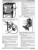
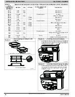
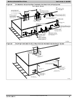
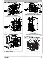
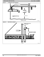
Horizontal Left Configurations (CONTINUED)
HORIZONTAL LEFT
−
LEFT VENT CONFIGURATION
Representative drawing only, some models may vary in appearance.
HORIZONTAL LEFT
−
RIGHT VENT CONFIGURATION*
* Requires accessory Internal Vent Kit
Representative drawing only, some models may vary in appearance.
* See NOTES following figures.
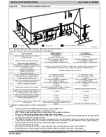
Figure 55
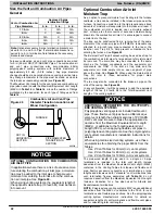
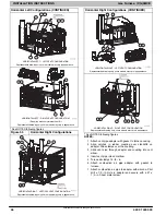
Horizontal Right Configurations
HORIZONTAL RIGHT
−
VERTICAL VENT CONFIGURATION
Representative drawing only, some models may vary in appearance.
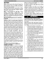
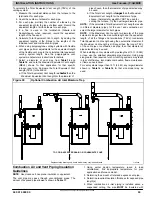
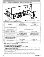
Horizontal Right Configurations (CONTINUED)
HORIZONTAL RIGHT
−
LEFT VENT CONFIGURATION
Representative drawing only, some models may vary in appearance.
HORIZONTAL RIGHT
−
RIGHT VENT CONFIGURATION
Representative drawing only, some models may vary in appearance.
* See NOTES following figures.
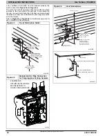
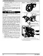
NOTES:
1. Attach vent pipe adapter with gasket to furnace casing.
2. Align notches in rubber coupling over standoffs on
adapter. Slide clamps over the coupling.
3. Slide vent pipe through adapter and coupling into vent
elbow.
4. Insert vent pipe into vent elbow.
5. Torque all clamps 15
−
lb.
−
in.
6. Attach combustion air pipe adapter with gasket to
furnace.
7. Attach combustion air pipe to adapter with silicone. Pilot
drill a
1/8
−
in. Hole in adapter and secure with a #7 x
1/2
−
in. Sheet metal screw.