Chapter 5 — Firmware Download
ED40 Decode Board Integration Guide
43
•
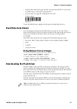
Send the Flash Memory Upgrade ISCP command (See the
ISCP Command Set
available from your Intermec representative).
•
Scan the firmware upgrade configuration bar code:
To exit download mode, simply turn the power off and then back on.
Baud Rate Auto-Detect
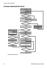
Once the imager is in firmware download mode, it waits for the auto-detect
character (0x00) from the host (no protocol used). When the imager receives this
character, it automatically detects the host baud rate and adapts itself
accordingly.
The UART of the host must be configured with the following parameters:
•
Baud rate: 9600, 19200, 38400, 57600, 115200, 128000, 230400, 256000
•
8 bits
•
no parity
•
no protocol used
Dialog Between Host and Imager
/*host initiates baud rate auto-detection*
host sends AUTO_DETECT (0x00)
/*imager detects host baud rate*/
imager replies BAUD_RATE_DETECTED (0x75)
/*imager now ready to receive flash driver*/
Downloading the Flash Driver
The flash driver is the tool used to communicate between the imager and the
host. It combines the different firmware download functions necessary to erase,
read from and write to the flash memory of the imager. This driver is downloaded
to the RAM memory of the imager (no protocol used).
The host opens the flash driver file (*.DRX) and determines the number of bytes
contained in the file.
The host calculates the number of blocks to send to the imager by dividing the
number of bytes in the file by 256. The host is now ready to initiate download.
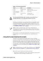
CCMD 30 01
Firmware upgrade
Note:
The flash driver file ( *.DRX) is provided by Intermec. Contact your
Intermec sales representative.
Содержание ED40
Страница 1: ...Decode Board Used with EA11 EA20X EA21 and EA30 Imagers ED40 Integration Guide EA11 EA20X EA21 EA30 ...
Страница 4: ...iv ED40 Decode Board Integration Guide ...
Страница 22: ...Chapter 2 Mechanical Integration 10 ED40 Decode Board Integration Guide ...
Страница 32: ...Chapter 3 Electrical Integration 20 ED40 Decode Board Integration Guide ...
Страница 41: ...Chapter 4 ED40 Setup ED40 Decode Board Integration Guide 29 UPC A SW 4B 40 01 UPC E SW 4B 41 01 ...
Страница 48: ...Chapter 4 ED40 Setup 36 ED40 Decode Board Integration Guide UPC A ...
Страница 50: ...Chapter 4 ED40 Setup 38 ED40 Decode Board Integration Guide ...
Страница 84: ...Appendix A EA11 Imager 72 ED40 Decode Board Integration Guide Scanning Current EA11 ED40 Scanning Current USB ...
Страница 92: ...Appendix A EA11 Imager 80 ED40 Decode Board Integration Guide ...
Страница 104: ...Appendix B EA20X Imager 92 ED40 Decode Board Integration Guide Scanning Current EA20X ED40 Scanning Current USB ...
Страница 122: ...Appendix C EA21 Imager 110 ED40 Decode Board Integration Guide Scanning Current EA21 ED40 Scanning Current USB ...
Страница 130: ...Appendix C EA21 Imager 118 ED40 Decode Board Integration Guide ...
Страница 142: ...Appendix D EA30 Imager 130 ED40 Decode Board Integration Guide Scanning Current EA30 ED40 Scanning Current USB ...
Страница 153: ...Appendix D EA30 Imager ED40 Decode Board Integration Guide 141 ...
Страница 154: ......


