


Appendix D — EA30 Imager
ED40 Decode Board Integration Guide
131
Motion Tolerance
One of the important features of the EA30 imager is it’s high level of motion
tolerance. Maximum motion tolerance for the EA30 is 500 inches per second.
In this section we provide 3 basic setup modes for motion tolerance:
•
Standard Motion Tolerance (default settings)
•
Improved Motion Tolerance
•
Maximum Motion Tolerance
Each setup mode uses 3 different setup parameters. The settings provided were
tested on code EAN, in typical office environment (250 lux) with the goal of
obtaining a high motion tolerance rate with an acceptable decode rate (not 100%).
Keep in mind that the settings may vary depending on your application and the
environment.
Note:
Setting up the imager for maximum motion tolerance will modify some
imager performances such as reading distances and peak current. This section
gives an idea of how different performances are affected.
Motion Tolerance Modes
Mode
Settings
Motion
Tolerance
Lighting Peak
Current
Imager Performance
Standard
(default)
Illumination level = 60
Lighting goal = 128
190 in/sec 500 mA
No degradation in imager performances.
Improved
Illumination level = 70
Lighting goal = 70
350 in/sec 700 mA
High contrast bar codes required.
Reading distances are decreased around 10%
compared to the standard mode.
Maximum
Illumination level = 100
Lighting goal = 46
500 in/sec 1200 mA
High contrast bar codes with a minimum
resolution of 0.125 mm/5 mils required.
Reading distances are decreased around 30%
compared to the standard mode.
Reading distances on DataMatrix 0.18 mm/7
mils can decrease up to 60%.
Содержание ED40
Страница 1: ...Decode Board Used with EA11 EA20X EA21 and EA30 Imagers ED40 Integration Guide EA11 EA20X EA21 EA30 ...
Страница 4: ...iv ED40 Decode Board Integration Guide ...
Страница 22: ...Chapter 2 Mechanical Integration 10 ED40 Decode Board Integration Guide ...
Страница 32: ...Chapter 3 Electrical Integration 20 ED40 Decode Board Integration Guide ...
Страница 41: ...Chapter 4 ED40 Setup ED40 Decode Board Integration Guide 29 UPC A SW 4B 40 01 UPC E SW 4B 41 01 ...
Страница 48: ...Chapter 4 ED40 Setup 36 ED40 Decode Board Integration Guide UPC A ...
Страница 50: ...Chapter 4 ED40 Setup 38 ED40 Decode Board Integration Guide ...
Страница 84: ...Appendix A EA11 Imager 72 ED40 Decode Board Integration Guide Scanning Current EA11 ED40 Scanning Current USB ...
Страница 92: ...Appendix A EA11 Imager 80 ED40 Decode Board Integration Guide ...
Страница 104: ...Appendix B EA20X Imager 92 ED40 Decode Board Integration Guide Scanning Current EA20X ED40 Scanning Current USB ...
Страница 122: ...Appendix C EA21 Imager 110 ED40 Decode Board Integration Guide Scanning Current EA21 ED40 Scanning Current USB ...
Страница 130: ...Appendix C EA21 Imager 118 ED40 Decode Board Integration Guide ...
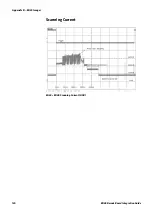
Страница 142: ...Appendix D EA30 Imager 130 ED40 Decode Board Integration Guide Scanning Current EA30 ED40 Scanning Current USB ...
Страница 153: ...Appendix D EA30 Imager ED40 Decode Board Integration Guide 141 ...
Страница 154: ......