Intel® Storage Server System JBOD 2000 Family Hardware Guide
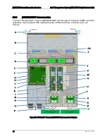
JBOD 2000 Internal Connection Overview
Revision 1.42
43
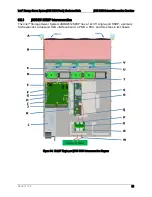
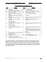
Table 26. 2U 24x2.5” Dual-port JBOD2000 Components
Label
Description
Label
Description
A
Front Panel
B
Front Panel Cable
C
HSBP Power Daisy Chain Cable
D
Three 60mm System Fans
E
2x15-pin Front Panel Connector on PDB
F
1x4-pin Expander Power Connector on PDB
G
Expander Power Cable
H
SMBus Connector on PDB
I
Four 2x4-pin HSBP Power Connectors on
PDB
J
2x25-pin PSU Connector on PDB
K
SMBus Connector on Primary and Second
Expander
L
Two PSUs
M
SFF-8087 Connector on Primary SAS
Converter
N
Primary SAS Interface Board (SFF-8087 to SFF-
8088)
O
SFF-8088 Connector on Primary SAS
Converter
Port 0 Label: A PRI
Port 1 Label: B PRI
P
External mini-SAS Cable (need to order
separately)
Q
SFF-8088 Connector on Second SAS
Converter
Port 0 Label: A SEC
Port 1 Label: B SEC
R
Second SAS Interface Board (SFF-8087 to SFF-
8088)
S
SFF-8087 Connector on Second SAS
Converter
T
Third SAS Interface Board (SFF-8087 to SFF-
8088)
Note
: It is under the second SAS converter, so it
is not shown in the diagram. Its external SFF-
8088 connector label is Port 0: C PRI, Port 1: C
SEC.
U
Expander Power Connector on Primary and
Second Expander
V
SMBus Cable
W
Primary SAS Expander
X
Second SAS Expander
Y
Fan Cable
Z
12 mini-SAS Connectors on HSBP
AA
Three 8x 2.5” Dual-port HSBPs
(each HSBP has four mini-SAS connectors)
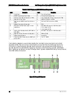
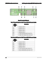
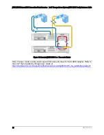
The following diagram is used to help identify the mini-SAS connectors found on the SAS
expander cards. Take care when connecting the connectors from the SAS expander to the
connectors on the backplane because each connector is pre-programmed at the factory to
provide specific drive identification mapping. Improper connections may provide undesirable
drive mappings. By default, the Intel
®
Storage System JBOD 2000 Family has all internal mini-
SAS cables connected.
Содержание JBOD 2000 Family
Страница 1: ...Intel Storage Server System JBOD 2000 Family Hardware Guide Revision 1 42 November 2015 ...
Страница 10: ......


