


Processor Thermal/Mechanical Information
R
18
Thermal/Mechanical Design Guide
2.1.2.3 Additional
Guidelines
In addition to the general guidelines given above, the heatsink attach mechanism for the Pentium
4 processor in the 775–land LGA package should be designed to the following guidelines:
•
Holds the heatsink in place under mechanical shock and vibration events and applies force to
the heatsink base to maintain desired pressure on the thermal interface material
. Note that
the load applied by the heatsink attach mechanism must comply with the package
specifications described in the processor datasheet. One of the key design parameters is the
height of the top surface of the processor IHS above the motherboard. The IHS height from
the top of board is expected to vary from 7.517 mm to 8.167 mm. This data is provided for
information only, and should be derived from:
⎯
The height of the socket seating plane above the motherboard after reflow, given in the
LGA775 Socket Mechanical Design Guide
with its tolerances
⎯
The height of the package, from the package seating plane to the top of the IHS, and
accounting for its nominal variation and tolerances that are given in the corresponding
processor datasheet.
•
Engages easily, and if possible, without the use of special tools
. In general, the heatsink is
assumed to be installed after the motherboard has been installed into the chassis.
•
Minimizes contact with the motherboard surface during installation
and actuation to avoid
scratching the motherboard.
2.2 Thermal
Requirements
Refer to the datasheet for the processor thermal specifications. The majority of processor power is
dissipated through the IHS. There are no additional components (e.g., BSRAMs) that generate
heat in this package. The amount of power that can be dissipated as heat through the processor
package substrate and into the socket is usually minimal.
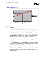
Intel has introduced a new method for specifying the thermal limits for the Pentium 4 Processor in
the 775–land LGA package. The new parameters are the Thermal Profile and T
CONTROL
. The
Thermal Profile defines the maximum case temperature as a function of power being dissipated.
T
CONTROL
is a specification used in conjunction with the temperature reported by the on-die
thermal diode. Designing to these specifications allows optimization of thermal designs for
processor performance and acoustic noise reduction.
2.2.1
Processor Case Temperature
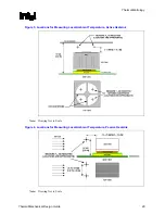
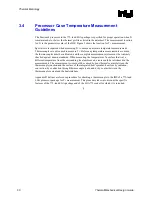
For the Pentium 4 processor in the 775–land LGA package, the case temperature is defined as the
temperature measured at the geometric center of the package on the surface of the IHS. For
illustration, Figure 2 shows the measurement location for a 37.5 mm x 37.5 mm
[1.474 in x 1.474 in] FCLGA4 package. Techniques for measuring the case temperature are
detailed in Section 3.4.
Note:
In case of conflict, the package dimensions in the processor datasheet supersedes dimensions
provided in this document.
Содержание 640 - Pentium 4 640 3.2GHz 800MHz 2MB Socket 775 CPU
Страница 14: ...Introduction R 14 Thermal Mechanical Design Guide ...
Страница 38: ...Thermal Management Logic and Thermal Monitor Feature R 38 Thermal Mechanical Design Guide ...
Страница 52: ...Intel Thermal Mechanical Reference Design Information R 52 Thermal Mechanical Design Guide ...
Страница 60: ...Acoustic Fan Speed Control R 60 Thermal Mechanical Design Guide ...
Страница 72: ...Heatsink Clip Load Metrology R 72 Thermal Mechanical Design Guide ...
Страница 97: ...Mechanical Drawings R Thermal Mechanical Design Guide 97 Figure 48 Reference Clip Drawings Sheet 1 ...
Страница 98: ...Mechanical Drawings R 98 Thermal Mechanical Design Guide Figure 49 Reference Clip Drawings Sheet 2 ...
Страница 99: ...Mechanical Drawings R Thermal Mechanical Design Guide 99 Figure 50 Reference Fastener Sheet 1 ...
Страница 100: ...Mechanical Drawings R 100 Thermal Mechanical Design Guide Figure 51 Reference Fastener Sheet 2 ...
Страница 101: ...Mechanical Drawings R Thermal Mechanical Design Guide 101 Figure 52 Reference Fastener Sheet 3 ...
Страница 102: ...Mechanical Drawings R 102 Thermal Mechanical Design Guide Figure 53 Reference Fastener Sheet 4 ...
Страница 103: ...Mechanical Drawings R Thermal Mechanical Design Guide 103 Figure 54 Clip Heatsink Assembly ...
Страница 104: ...Mechanical Drawings R 104 Thermal Mechanical Design Guide Figure 55 Intel R RCBFH 3 Reference Solution Assembly ...


