background image


130 

BMC Settings 

7.9


Fault Diagnosis 

Diagnostic tool provides the ability of check and verification for BMC or Host system to 
check whether there is something out of function or something does not work correctly. 

7.9.1


BMC Self-inspection Result 

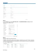
On the WEB GUI, go to the Fault Diagnosis 

BMC Self-inspection Result to displays the 

BMC self-inspection codes. 


The following table shows the BMC self-inspection code. 

Self-inspection code 

Description 

0x55 

SFT_CODE_OK 

0x56 

SFT_CODE_NOT_IMPLEMENTED 

0x57 

SFT_CODE_DEV_CORRUPTED 

0x58 

SFT_CODE_FATAL_ERROR 

0xff 

SFT_CODE_RESERVED 

0x80 

SEL_ERROR 

0x40 

SDR_ERROR 

0x20 

FRU_ERROR 

0x10 

IPMB_ERROR 

0x08 

SDRR_EMPTY 

0x04 

INTERNAL_USE 

0x02 

FW_BOOTBLOCK 

0x01 

FW_CORRUPTED 

7.9.2


BMC Recovery 

Users can reset BMC through WEB or IPMI CMD in case of an abnormal situation occurs.


On the WEB GUI, go to the Fault Diagnosis 

BMC Recovery to reset BMC or KVM.  

To reset BMC, select the BMC Warm Reset (it uses WEB or IPMI CMD “ipmitool mc reset” 
to reset BMC). To reset KVM, select the KVM Service Restart (KVM server will be reset).


Содержание ON5263M5

Страница 1: ...Inspur Server User Manual ON5263M5 ...

Страница 2: ... illustrations and information related to Inspur product is protected under international copyright laws Reproduction of this manual or the material contained herein in any form or by any means without the written permission of Inspur is strictly forbidden The information in this manual is subject to change without notice The latest manual or characterized errata are available on request Images pr...

Страница 3: ... extend configuration or connect other peripheral devices arbitrarily If needed please contact Inspur for our support and guidance Before disassembling the server s components please be sure to disconnect all the power cords connected to the server BIOS and BMC setup is a significant factor in correctly configuring your server If there are no special requirements it is suggested to use the Default...

Страница 4: ...kage Contents 11 4 2 Power On Off 11 4 3 Pre disassembly Instructions 11 4 4 Disassembly Reassembly Process 12 4 4 1 Air Baffle Replacement 12 4 4 2 Fan Module Replacement 14 4 4 3 DIMM Replacement 14 4 4 4 PCIe Riser Card Assembly Replacement 16 4 4 5 M 2 SSD Replacement 17 5 Setup 19 5 1 Operational Requirements 19 5 1 1 Space and Airflow 19 5 1 2 Temperature 20 5 1 3 Power 20 5 1 4 Electrical G...

Страница 5: ... LAN Configuration 46 6 2 2 7 USB Devices Information 46 6 2 2 8 Network Stack Configuration 47 6 2 2 9 iSCSI Configuration 48 6 2 3 Chipset 51 6 2 3 1 PCH SATA sSATA Configuration 51 6 2 3 2 USB Configuration 52 6 2 3 3 Miscellaneous Configuration 53 6 2 3 4 Server ME Configuration 54 6 2 3 5 Runtime Error Logging 54 6 2 4 Processor 55 6 2 4 1 Processor Configuration 55 6 2 4 2 Common Configurati...

Страница 6: ...2 1 4 LAN interfaces 86 7 2 1 5 IPMI Commands 86 7 2 2 Web GUI 94 7 2 2 1 Web GUI Login 95 7 2 2 2 Web GUI Introduction 96 7 2 2 3 Web GUI Features 96 7 2 3 SNMP 99 7 2 4 Smash Lite CLI 100 7 2 4 1 Command Line Login 100 7 2 4 2 Command Line Features 100 7 3 System Overview 103 7 3 1 System Running State 103 7 3 2 Management Device BMC Information and Server information 105 7 3 3 Quick Launch 105 ...

Страница 7: ...8 7 6 1 Server Power Control 118 7 6 2 Fan Speed Control 119 7 7 BMC Settings 120 7 7 1 BMC Network Management 120 7 7 2 Service Settings 121 7 7 3 NTP Settings 122 7 7 4 SMTP Settings 123 7 7 5 Alert Management 123 7 7 6 Access Control 125 7 7 7 BIOS Boot Options 125 7 8 Logs 125 7 8 1 System Event Log 126 7 8 2 BMC System Audit Log 127 7 8 3 Event Log Setting 128 7 8 4 System Audit Log Settings ...

Страница 8: ...e 139 7 10 6 Restore Factory Defaults 141 7 11 Device State Monitor and Diagnostic 142 7 11 1 Sensors 142 7 11 1 1 Physical Sensors 142 7 11 1 2 Virtual Sensors 143 7 11 1 3 Event Only sensors 143 7 11 1 4 Sensor attribute 143 7 11 2 CPU 144 7 11 3 Memory 144 7 12 Event Alerts 144 7 12 1 SMTP Email Alerts 144 7 12 2 Syslog 146 7 13 BMC Self Recovery 146 7 13 1 Hardware Watchdog 146 7 13 2 Software...

Страница 9: ...ommission Notice 151 10 2 1 FCC Rating Label 151 10 3 Battery Replacement Notice 152 11 Electrostatic Discharge 153 11 1 Preventing Electrostatic Discharge 153 11 2 Grounding Methods to Prevent Electrostatic Discharge 153 12 Warranty 154 12 1 Warranty Service 154 12 2 Inspur Service SLA 155 12 3 Warranty Exclusions 156 ...

Страница 10: ...nsure that the total rating of all equipment plugged into the extension cable does not exceed 80 percent of the ratings limit for the extension cable 4 Please be sure to use the power supply components that come with the server such as power lines power socket if provided with the server etc For your safety please do not replace power cables or plugs randomly 5 Toprevent electric shock dangers cau...

Страница 11: ...nto the rack only one component can be pulled out from the rack through its sliding part at one time Pulling out several components at the same time may cause the rack to turn over resulting to serious personal injury 11 A minimum of two people are required to safely move a rack The racks are extremely awkward and heavy moving them without adequate trained personnel could result in severe injury o...

Страница 12: ...ttention to the followings 1 In the case of thunder and lightning please do not connect or use the modem 2 Never connect or use the modem in a damp environment 3 Never insert the modem or telephone cables into the socket of network interface controller NIC 4 Before unpacking the product package installing internal components touching uninsulated cables or jacks of the modem please disconnect the m...

Страница 13: ...the edges of the plug in cards and components and or their metal fixed supports 8 During the process of rack installation and application please pay attention to the followings 1 After the rack installation is finished please ensure that the stabilizers have been fixed to the rack and supported to ground and the weight of the rack is firm on ground 2 When pulling out the components from the rack a...

Страница 14: ...le versatile workloads among current datacenters ON5263M5 has one 1 SATA PCIE M 2 two 2 PCIe expansion slots and one 1 OCP 2 0 slot at the front side providing the ultimate flexibility for scale out solutions With modularized design users can swap the selected front I O modules to fulfill hardware requirements according to the multiple applications Following the principle of OCP ON5263M5 can be in...

Страница 15: ...n3 x16 FHFL Option 2 One PCIe Gen3 x16 HHHL Two PCIe Gen3 x8 HHHL OCP Slot One OCP card OCP2 0 x16 slot on the motherboard Storage Drive One SATA PCIe x4 M 2 card on the motherboard Power Centralized OCP Power Shelf compliant with Open Rack v2 Physical Dimension 830mm L 537mm W 95 2mm H Product Weight Full configuration 7kg Cubby weight 15kg one cubby is available for 3 compute sleds Environmental...

Страница 16: ... Product Overview 3 Product Overview 3 1 Front View Item 1 UID Button with LED 2 Power Button 3 Thumb Screw for Cubby 4 OCP Connector x2 5 VGA Port 6 USB 3 0 Port x2 7 IPMI Port 8 PCIe Riser Card Module ...

Страница 17: ...8 Product Overview 3 2 Rear View Item 1 Fan Module x2 2 Power Connector ...

Страница 18: ...tem Item 1 Fan Connector 9 OCP Slot B 2 Fan Connector 10 VGA Port 3 Power Connector 11 USB 3 0 Port x2 4 PCH 12 IPMI Port 5 Power Button 13 M 2 Card Slot 6 UID Button 14 PCIe Riser Slot 7 OCP Slot A 15 M 2 Card Snap Clip 8 OCP Slot C CPU0 CPU1 ...

Страница 19: ... 4 Exploded Diagram The following illustration shows the major components in the server Item 1 Air Baffle 2 8056 Fan Module x2 3 DIMM Module x16 4 M 2 Card 5 Base with Motherboard 6 OCP Card 7 PCIe Card 8 PCIe Riser Module ...

Страница 20: ...or damage to the equipment remove the power cord to disconnect power from the server The Power button does not shut off the system power completely Portions of the power supply and some internal circuitry remain active until the AC power is removed 4 3 Pre disassembly Instructions Read the installation instructions for all the hardware operations before disassembling or re assembling the component...

Страница 21: ...e 4 4 Disassembly Reassembly Process NOTE During installation or removal of any hardware always ensure all data is backed up properly Disconnect any cables from the server Disconnect the server and all attached devices from their electrical outlets Item appearance may be different on actual models 4 4 1 Air Baffle Replacement CAUTION For proper cooling do not operate the server without the air baf...

Страница 22: ...he locking tabs are released from the server remove the air baffle 3 Follow the preceding steps to install the air baffle NOTE Make sure that both locking tabs are firmly secured on the server base when installing the air baffle ...

Страница 23: ...he fan module 4 4 3 DIMM Replacement WARNING Always wear an electrostatic discharge strap or gloves when removing or installing DIMM modules 1 Remove the air baffle Refer to Air Baffle Replacement 2 Locate the DIMM slot see the DIMM slot layout Determine which DIMM you want to replace 3 Carefully open the retaining clips on both end of the DIMM slot NOTE Make sure that both retaining clips on the ...

Страница 24: ... Make sure that retaining clips engage the notches on the DIMM If the retaining clips are not in the fully closed position the DIMM has not been correctly installed Press the DIMM firmly into the slot again until the retaining clips are fully seated DIMM slot layout DIMM population sequence The white slots take the priority while CPU1 DIMM shall be symmetrically installed with CPU0 DIMM For the si...

Страница 25: ...tion follows the screen printed sequence CPU1_C0D0 CPU1_C1D0 CPU1_C2D0 4 4 4 PCIe Riser Card Assembly Replacement 1 Loosen the screw securing the PCIe riser card assembly to the motherboard 2 Lift up and remove the PCIe riser card assembly from the motherboard connector 3 Remove the PCIe riser securing bracket from the PCIe riser module ...

Страница 26: ...l the PCIe riser card assembly NOTE Make sure that the PCIe riser card assembly is firmly connected to the motherboard connector before tightening the screw to secure the PCIe riser card assembly in place 4 4 5 M 2 SSD Replacement 1 Remove the PCIe riser card assembly Refer to PCIe Riser Card Assembly Replacement 2 Using your fingers gently pull up the snap clip ...

Страница 27: ...ding steps to install the M 2 SSD NOTE Make sure that the snap clip is fully engage with the notch on the SSD If the snap clip is not in the fully closed position the SSD has not been correctly installed Press the snap clip firmly into the notch again until the SDD is fully secured in place ...

Страница 28: ...bient room air to enter the cabinet and the rear door must be adequately ventilated to allow the warm air to flow out from the cabinet CAUTION To prevent improper cooling and damage to the equipment do not block the ventilation openings Always use blanking panels to fill empty vertical spaces in the rack When the rack is not filled by a server or rack component the gaps between the components caus...

Страница 29: ...ipment do not overload the AC supply branch circuit that provides power to the rack Consult the electrical authority having jurisdiction over wiring and installation requirements of your facility CAUTION Protect the server from power fluctuations and temporary interruptions with a regulating uninterruptible power supply UPS This device protects the hardware from damage caused by power surges and v...

Страница 30: ...are listed or certified grounding type devices Because of the high ground leakage currents associated with multiple servers connected to the same power source Inspur recommends the use of a PDU that is either permanently wired to the building s branch circuit or includes a non detachable cord that is wired to an industrial style plug NEMA locking style plugs or those complying with IEC 60309 are c...

Страница 31: ... partitions are larger than 2 2 TB Supports UEFI Shell providing a pre boot environment for running scripts and tools Supports UEFI Secure Boot Intel TXT Boot Guard and other security technologies with a stronger security performance NOTE Before changing the BIOS settings please backup all the original settings When the system works abnormally due to the modifications you can restore it with the b...

Страница 32: ...F11 to enter the boot management menu 4 Press F12 to enter the Preboot eXecution Environment PXE Table 6 1 BIOS Setup Control Key Instruction Table Key Function Esc Exit or return from submenu to main menu or Select a menu or Move the cursor up or down Home or End Move the cursor to the top or bottom of the screen or Select the previous or next numerical value or setting of the current one F1 Help...

Страница 33: ...sion memory and other information For more information on Main menu see 6 2 1 Main 6 1 2 CPU Information To view the CPU information login to the BIOS Setup Menu and select Processor Processor Configuration Processor Information For more information on CPU see 6 2 4 1 Processor Configuration 6 1 3 Memory Information To view the memory information login to the BIOS Setup Menu and select Processor M...

Страница 34: ...s under the Option ROM execution Network Storage Video OPROM Policy and Other PCI devices must set to Legacy Mode as well If the Boot Mode is set to UEFI Mode the options under the Option ROM execution Network Storage Video OPROM Policy and Other PCI devices are suggested to set to UEFI Mode If there are special requirements it can be set to Legacy Mode 6 1 5 RAID Volume Configuration To view the ...

Страница 35: ...ATA Configuration SATA Mode Options and press to change the item to RAID 3 Press F10 to save exit the BIOS Setup The system will reboot automatically 4 Login to the BIOS Setup Menu select Advanced CSM Configuration Boot Mode and press to change the item to UEFI 5 When the Boot Mode is set to UEFI the Intel R VROC SATA Controller menu appears on the Advanced menu Press Enter to show the HDD informa...

Страница 36: ...de on 2 HDDs RAID10 RAID0 1 This RAID volume is allowed to be made on 4 HDDs which is only available when HDD quantity is 4 or above RAID5 Parity This RAID volume is allowed to be made on 3 or more than 3 HDDs Select Disks Select which HDDs to make the RAID volume Capacity Set the volume capacity When highlight this item the maximum capacity is shown in the Help area on the right side Create Volum...

Страница 37: ...I Mode 1 After creating a RAID Volume successfully the RAID Volume information will appear on Advanced Intel R VROC SATA Controller menu Press Enter to show the detailed information 2 Press Enter to delete the RAID Volume 3 Confirm the deletion action ...

Страница 38: ...he information HDD ID HDD type HDD capacity volume member or not of HDDs connected to SATA controller and the existed RAID volumes information including volume ID name RAID level capacity status bootable Table 6 3 SATA RAID Configuration Interface Parameter Description Create RAID Volume Create an RAID volume Delete RAID Volume Delete an existed RAID volume Reset Disks to Non RAID Reset the HDDs i...

Страница 39: ...Options RAID0 Stripe This RAID volume is allowed to be made on 2 or more than 2 HDDs RAID1 Mirror This RAID volume is allowed to be made on 2 HDDs RAID10 RAID0 1 This RAID volume is allowed to be made on 4 HDDs which is only available when HDD quantity is 4 or above RAID5 Parity This RAID volume is allowed to be made on 3 or more than 3 HDDs Select Disks Select which HDDs to make the RAID volume S...

Страница 40: ...rface Select Delete RAID Volume and press Enter 2 Press Del to delete the selected RAID Volume 3 Confirm the deletion action To reset the HDD Disks to Non RAID Volumes under Legacy Mode 1 Use the or keys to select Reset Disks to Non RAID and press Enter 2 Use the space key to select the HDD to be reset and press Enter to reset the selected HDD 3 Confirm the deletion action ...

Страница 41: ...se the or keys to select Mark Disks as Spare and press Enter 2 The non RAID HDDs will be displayed on the screen Use the space key to select the HDD to be marked as spare and press Enter NOTE All data on the marked disk will be lost as the spare disk 3 Confirm the mark action ...

Страница 42: ...etwork Configuration Address Source Display the current BMC network parameters NOTE This item is only available when Get BMC Dedicated Parameters is set to Manual Unspecified Options Unspecified Unspecified option will not modify any BMC network parameters during BIOS phase Static Statically obtain BMC network information DynamicBmcDhcp Dynamically obtain BMC network information NOTE Static and dy...

Страница 43: ...ssage appears Press Enter to continue 3 At the Station IP address prompt type the station IP address and then press Enter 4 If the setting was successful the Set Static BMC Station IP OK appears If the setting was failed the Set Static BMC Station IP Fail appears If the IP address was the same the Static BMC Station IP Not Change appears If the IP address was invalid the Invalid Station IP Entered...

Страница 44: ...o change the setting for Station IP address to change the settings for Subnet mask Station MAC address and Router IP address To configure the BMC Dynamic network parameters 1 Set the Get BMC Sharelink Parameters or Get BMC Dedicated Parameters to Manual 2 Set the Configuration Address Source to DynamiBmcDhcp The Set Dynamic BMC IP Address Source Success message appears Press Enter to continue ...

Страница 45: ...ttings 3 Wait for 30 seconds press Enter when the Get Dynamic BMC Dhcp Sucess appears 4 The BMC network parameters Station IP address Subnet mask Station MAC address and Router IP address will be set dynamically ...

Страница 46: ...rs needs to be set to Do nothing or Manual then set to Auto the function will take effect 6 2 BIOS Setup Menu To access the BIOS Setup Menu press the DEL key during the POST when the power is turned on The following sections describe the eight BIOS Setup menu options Main Advanced Chipset Processor Server Management Security Boot and Save Exit respectively 6 2 1 Main The Main menu shows a summary ...

Страница 47: ...lled AEP memory size System Memory Speed The installed memory speed System Language Display and set the system language System Date mm dd yyyy Display and set the system date System Time hh mm ss Display and set the system time NOTE Use Tab or Enter key to switch between system date and time directly input the value or use keys to change the value Press key the value increases by 1 and press key t...

Страница 48: ...vice Support TPM Security device support settings Options Enabled Disabled NOTE BIOS supports TPM TCG version 1 2 2 0 BIOS supports TPM module through TPM software binding when the verification of software binding fails BIOS will record the error to SEL Enabled No Security Device Found Display the status of security device NOTE This item is only available when the TPM chip is installed ...

Страница 49: ...Port 0 Configuration Press Enter for configuration of advanced items Serial Port 1 Configuration Press Enter for configuration of advanced items Serial Port 0 1 Configuration enables disables the Serial Port COM When set to Enabled allows the user to configure the Serial Port 0 1 settings When set to Disabled displays no configuration for the Serial Port ...

Страница 50: ... Auto I0 3F8h IRQ 4 I0 3F8h IRQ 3 4 5 6 7 9 10 11 12 I0 2F8h IRO 3 4 5 6 7 9 10 11 12 I0 3E8h IRQ 3 4 5 6 7 9 10 11 12 I0 2E8h IRQ 3 4 5 6 7 9 10 11 12 Auto 6 2 2 3 Serial Port Console Redirection Set the Serial Port console redirection Table 6 10 Advanced Serial Port Console Redirection Parameter Description Default Setting Format Console Redirection Com0 Com1 Select whether to enable console red...

Страница 51: ...edirection Console Redirection Settings Parameter Description Default Setting Format Terminal Type Select a terminal type to be used for console redirection Options VT100 VT100 VT UTF8 ANSI ANSI Bits per second Select the transfer rate Options 9600 19200 38400 57600 115200 115200 Data Bits Select the number of data Options 7 8 8 Parity A parity bit can be sent with the data bits to detect some tra...

Страница 52: ...start stop signals Options None and Hardware RTS CTS None VT UTF8 Combo Key Support Enable Disable the VT UTF8 Combo Key Support Options Enabled Disabled Enabled Recorder Mode When this mode enabled only texts will be send This is to capture Terminal data Options Enabled Disabled Disabled Redirection 100 31 Enable Disable extended terminal resolution Options Enabled Disabled Disabled Putty KeyPad ...

Страница 53: ...his item Enable Disable Single Root IO Virtualization Support Options Enabled Disabled Enabled 6 2 2 5 CSM Configuration Set the compatibility support module CSM configuration Table 6 13 Advanced CSM Configuration Parameter Description Default Setting Format CSM Support Enable Disable the Compatibility Support Module CSM support Options Enabled Disabled Enabled GateA20 Active When set to Upon Requ...

Страница 54: ...ilable when CSM Support is set to Enabled Immediate Boot Mode Set the Boot mode Options Legacy Mode UEFI Mode For more information refer to 6 1 4 UEFI Legacy Mode UEFI Mode Network Control the execution of UEFI and Legacy PXE Option ROM Options Do not launch Legacy UEFI UEFI Storage Control the execution of UEFI and Legacy Options Do not launch Legacy UEFI UEFI Video OPROM Policy Control the execu...

Страница 55: ... Description Default Setting Format Onboard PHY Card Control Enable disable the Onboard PHY card Options Enabled Disabled Enabled PHY NIC MAC Address Display the PHY NIC1 NIC2 MAC address NIC PXE ROM Enable disable the NIC PXE ROM feature Options Enabled Disabled Enabled 6 2 2 7 USB Devices Information Display the USB devices connected to the system ...

Страница 56: ...ature Options Enabled Disabled Enabled Ipv4 HTTP Support Enable Disable the Ipv4 HTTP feature Options Enabled Disabled Disabled Ipv6 PXE Support Enable Disable the Ipv6 PXE feature Options Enabled Disabled Disabled Ipv6 HTTP Support Enable Disable the Ipv6 HTTP feature Options Enabled Disabled Disabled IPSEC Certificate Enable Disable the IPSEC certificate feature Options Enabled Disabled Enabled ...

Страница 57: ... virtual drive is mainly used to run a supported operating system residing on an external server and a supported operating system used as a local server host operating system Press Enter to specify the iSCSI initiator name in iSCSI Qualified Name iqn format for example iqn 2019 07 com inspur 000000 Add an Attempt Submenu ...

Страница 58: ...rable Configure ISID Configure the out format ISID Enable DHCP Enable disable DHCP Options Enabled Disabled Disabled Initiator IP Address Enter IP address in dotted decimal notation 0 0 0 0 Initiator Subnet Mask Enter IP address in dotted decimal notation 0 0 0 0 Gateway Enter IP address in dotted decimal notation 0 0 0 0 Target Name The worldwide unique name of the target Only iqn Format is accep...

Страница 59: ...ubmenu Delete one or more attempts by setting the item to Enabled Change Attempt Order Submenu Change the order of Attempts using keys Use arrow keys to select the attempt then press to move the attempt up down in the attempt order list ...

Страница 60: ...em to malfunction The Chipset menu allows the user to configure the function and runtime error logging settings of PCH SATA sSATA USB and ME devices To access the submenu item press the Enter key 6 2 3 1 PCH SATA sSATA Configuration Display and set the HDD information of onboard SATA ports sSATA ports ...

Страница 61: ...ns will be disabled and the RAID setup utility cannot be accessed at boot time When set to RAID the SATA controller enables both its RAID and AHCI functions The RAID setup utility is allowed to access at boot time Options AHCI RAID NOTE This item is only available when SATA Controller is set to Enabled AHCI SATA Port Display the SATA port HDD information Port Enable disable the SATA port Options E...

Страница 62: ...d to SD card Options Enabled Disabled Disabled USB Port Connected to BMC Enable disable the USB port connected to BMC Options Enabled Disabled Enabled 6 2 3 3 Miscellaneous Configuration Display and set the other common options Table 6 18 Chipset Miscellaneous Configuration Parameter Description Default Setting Format Restore AC Power Loss Specify what state to go to when a power failure G3 State ...

Страница 63: ...ting Format Options 1GB 2MB VGA Priority Set the VGA device priority Options Onboard Device Offboard Device Onboard Device 6 2 3 4 Server ME Configuration Display and set the server ME information 6 2 3 5 Runtime Error Logging Set the system error logs ...

Страница 64: ...6 2 4 Processor The Processor menu allows the user to configure the processor and memory information To access the submenu item press the Enter key 6 2 4 1 Processor Configuration Configure the system processor settings ...

Страница 65: ...he Intel Trusted Execution Technology function Options Enabled Disabled Disabled VMX Enable disable the Intel virtual machine extensions function Options Enabled Disabled Enabled SMX Enable disable the safe mode extension function Options Enabled Disabled Disabled Hardware Prefetcher Prefetch the instructions or data from memory to L2 cache before CPU processing these instructions or data to short...

Страница 66: ...disable all threads LLC Options Enabled Disabled Disabled DCU Mode Set the DCU mode Options 32KB 8Way Without ECC 16KB 4Way With ECC 32KB 8Way Without ECC Extended APIC Enable disable the extended APIC Options Enabled Disabled Enabled AES NI Control whether the CPU supports AES instruction Options Enabled Disabled Enabled 6 2 4 2 Common Configuration Configure the system common options for process...

Страница 67: ...ources Options Enabled Disabled Enabled 6 2 4 3 UPI Configuration Configure the system UPI settings Table 6 20 Processor UPI Configuration Parameter Description Default Setting Format Degrade Precedence When the system settings conflict set this item to reduce Feature or to reduce Topology Options Topology Precedence Feature Precedence Topology Precedence Link Speed Mode Link speed mode settings O...

Страница 68: ...ring Sub NUMA cluster settings Options Auto Support 1 cluster or 2 clusters according to IMC interleave Enabled Support all SNC clusters 2 clusters and 1 way IMC interleave Disabled SNC function not supported Disabled XPT Prefetch Enable disable the XPT Prefetch Options Enabled Disabled Disabled KTI Prefetch Enable disable the KTI Prefetch Options Enabled Disabled Enabled Legacy VGA Socket Set the...

Страница 69: ...d Disabled Enabled Legacy ADR Mode Enable disable the Legacy ADR Options Enabled Disabled Disabled ADR Data Save Mode Set the ADR data save mode Options Disabled Batterybacked DIMMs NVDIMMs NVDIMMs Erase Arm NVDIMMs Erase Arm NVDIMMs settings Options Enabled Disabled Enabled Restore NVDIMMs Restore NVDIMMs settings Options Enabled Disabled Enabled Interleave NVDIMMs Interleave NVDIMMs settings Opt...

Страница 70: ...d 1LM Memory Interleave Granularity 1LM memory interleave granularity settings Options Auto 256B Target 256B Channel 64B Target 64B Channel Auto IMC Interleaving IMC interleaving settings Options Auto 1 way Interleavel 2 way Interleavel Auto Channel Interleaving Channel interleaving settings Options Auto 1 way Interleavel 2 way Interleavel 3 way Interleavel Auto Rank Interleaving Rank interleaving...

Страница 71: ...led Mirror TAD0 Mirror TAD0 mode settings Options Enabled Disabled Disabled Enable Partial Mirror Enable partial mirror mode settings Options Disabled Partial Mirror mode 1LM Disabled UEFI ARM Mirror UEFI ARM mirror mode settings Options Enabled Disabled Disabled Memory Rank Sparing Memory Rank sparing settings Options Enabled Disabled When set to Enabled user can select the memory sparing mode Th...

Страница 72: ...trol Scrub Interval Patrol Scrub interval settings the unit is hour and the range is 0 24 When set to 0 it means auto 24 Patrol Scrub Address Mode Patrol Scrub address mode settings Options System Physical Address Reverse Address System Physical Address 6 2 4 5 IIO Configuration Configure the system PCIe slot settings Table 6 23 Processor IIO Configuration Parameter Description Default Setting For...

Страница 73: ... Only Disabled PCIe Max Read Request Size PCIe max read request size settings Options Auto 128B 256B 512B 1024B 2048B 4096B Auto 6 2 4 6 Advanced Power Management Configuration Configure the CPU power management Table 6 24 Processor Advanced Power Management Configuration Parameter Description Default Setting Format Power Performance Profile Power Performance profile settings Options Maximum Perfo...

Страница 74: ... items SOCKET RAPL Config Press Enter for configuration of advanced items CPU P State Control Submenu Table 6 25 Processor Advanced Power Management Configuration CPU P State Control Parameter Description Default Setting Format Uncore Freq Scaling UFS Enable disable the autonomous uncore frequency scaling Options Enabled Disabled Min Frequency Disabled MAX Frequency Custom Enabled SpeedStep Pstate...

Страница 75: ...o Boost Technology Options Enabled Disabled Enabled Hardware PM State Control Submenu Table 6 26 Processor Advanced Power Management Configuration Hardware PM State Control Parameter Description Default Setting Format Hardware P States Set the hardware P States Options Disabled based on legacy OS request Native Mode based on legacy OS boot Out of Band Mode hardware auto select no OS boot Native Mo...

Страница 76: ...t Support Enable disable the Monitor Mwait instruction Options Enabled two way Disabled four way Disabled Autonomous Core C State Enable disable the autonomous core C state Options Enabled Disabled Disabled CPU C6 report Enable disable the C6 state to OS reports Options Enabled Disabled Disabled Enhanced Halt State C1E Enable disable the C1E feature Options Enabled Disabled Disabled ...

Страница 77: ...6 28 Processor Advanced Power Management Configuration Package C State Control Parameter Description Default Setting Format Package C State Package C state settings Options C0 C1 state C2 state C6 non Retention state C6 Retention state No Limit C0 C1 state ...

Страница 78: ...ting Format Power Performance Tuning Power performance tuning settings Options OS Controls EPB BIOS Controls EPB BIOS Controls EPB ENERGY_PERF_BIAS_CF G Mode Power performance management settings Options Performance Balanced Performance Balanced Power Power NOTE This item is only available when Power Performance Tuning is set to BIOS Controls EPB Performance Workload Configuration Workload optimiz...

Страница 79: ...meter Description Default Setting Format PL1 Power Limit PL1 power limit settings 0 PL1 Time Window PL1 time window settings the range is 0 56 1 PL2 Limit Enable disable the PL2 limit function Options Enabled Disabled Enabled PL2 Power Limit PL2 power limit settings 0 PL2 Time Window PL2 time window settings the range is 0 56 1 ...

Страница 80: ... firmware version information FRB 2 Timer Enable Disable FRB 2 timer POST timer Options Enabled Disabled Enabled FRB 2 Timer Timeout Configure the FRB2 Timer timeout Options 3 minutes 4 minutes 5 minutes 6 minutes NOTE This item is only available when FRB 2 Timer is set to Enabled 6 minutes FRB 2 Timer policy Configure the FRB2 Timer policy Options Do Nothing Reset Power Down Power Cycle NOTE This...

Страница 81: ... Timer Policy Options Do Nothing Reset Power Down Power Cycle NOTE This item is only available when OS Watchdog Timer is set to Enabled Reset BMC Network Configuration Press Enter for configuration of advanced items BMC User Settings Press Enter for configuration of advanced items VLAN Configuration Press Enter for configuration of advanced items View FRU information Press Enter for configuration ...

Страница 82: ...Network Enable disable the Sharelink network function Options Enabled Disabled Enabled BMC IPv4 Network Configuration Press Enter for configuration of advanced items BMC IPv6 Network Configuration Press Enter for configuration of advanced items BMC IPv4 Network Configuration Submenu BMC IPv6 Network Configuration Submenu ...

Страница 83: ...rs Set the method to get the BMC sharelink parameters Options Do Nothing Auto Manual Do Nothing Get BMC Dedicated Parameters Set the method to get the BMC dedicated parameters Options Do Nothing Auto Manual Do Nothing For more information see 6 1 6 Configuring the BMC Network 6 2 5 2 BMC User Settings Configure the BMC users Press Enter for configuration of advanced items ...

Страница 84: ...tain uppercase and lowercase letters special characters and numbers within 8 20 characters User Access Enable disable the user access settings Options Enabled Disabled Disabled Channel No Set the BMC channel input 1 or 8 0 User Privilege Limit User privilege settings Options Reserved Callback User Operator Administrator Reserved If the setting succeeds it will prompt Set User Access Command Passed...

Страница 85: ...C User Settings Delete User Parameter Description Default Setting Format User Name Enter the user name you want to delete User Password Enter the password to confirm the deletion If the setting succeeds it will prompt User Deleted and take effect immediately Change User Settings Submenu Modify the BMC user settings See Table 6 34 for the operation ...

Страница 86: ...rtual LAN VLAN Table 6 36 Server Mgmt VLAN Configuration Parameter Description Default Setting Format Sharelink Dedicated VLAN Control Enable disable BMC sharelink dedicated VLAN function Options Enabled Disabled NOTE To enable VLAN it needs to set the Disabled ...

Страница 87: ...cated VLAN Priority Set the BMC sharelink dedicated VLAN priority the range is 1 7 NOTE The setting takes effect immediately 1 6 2 5 4 View FRU information Display the basic system ID information as well as System product information Items on this window are non configurable NOTE The model name will vary depends on the product you purchased 6 2 6 Security The Security menu allows the user to confi...

Страница 88: ...er to set a new password It must contain uppercase and lowercase letters special characters and numbers within 8 20 characters 6 2 7 Boot The Boot menu allows the user to configure the boot mode boot priority and boot procedure Table 6 37 Boot Menu Parameter Description Default Setting Format ...

Страница 89: ...d EFI Shell To Boot Option Add the EFI Shell to the Boot Option Options Enabled Disabled Disabled Quiet Boot Enable disable the quite boot feature Options Enabled Disabled If set to Enabled the boot logo displays during POST If set to Disabled a text mode boot screen displays Enabled Boot Order Priorities Press Enter on Boot Option to change the priority Driver BBS Priorities Press Enter on Driver...

Страница 90: ...ell 1 When Inspur Logo appears on the screen during system booting press F11 key to enter the Boot Menu 2 Highlight UEFI Built in EFI Shell and press Enter 3 Type cd afuefi64 the location where the disk stores the AfuEfi64 package and type dir to enter the aafuefi64 folder The BIOS bin file contains the 32M BIOS and ME file 4 Execute the command to update the 16M BIOS ...

Страница 91: ...electricity on the motherboard and then power it on 6 3 2 AMI Flash Utility To update the firmware in Linux 1 Boot the system to Linux OS 2 Enter the directory containing the afulnx_64 tool for Linux 64bit OS or afulnx_32 tool for Linux 32bit OS 3 Copy the BIOS bin file into this folder 4 Execute the command to update BIOS afulnx_64 BIOS bin b p n x k l ...

Страница 92: ...tool as root After the update is complete power off the server confirm that there is no residual electricity on the motherboard and then power it on NOTE Parameter Instruction B Program Boot Block P Program main bios image N Program NVRAM X Do not check ROM ID K Program all non critical blocks L Program all ROM Holes ME Program ME Entire Firmware Block ...

Страница 93: ...d carries out corresponding solutions according to the information State monitoring Monitors the running states of all monitoring units in real time Device information management Provides device version model and asset information Heat dissipation control It could adjust fan speed dynamically according to the ambient temperature and workload IPMITool management Supports the command operation sent ...

Страница 94: ...ual Media Serial Over Lan SOL Diagnostic Log System Event Log SEL Inspur Diagnostic Logs and One key collection log BMC hardware watchdog timer if the BMC does not respond within four minutes the fan will reach full speed Support Intel Intelligent Power Node Manager 4 0 Event Alert SNMP Trap v1 v2c v3 Email Alert and Syslog Dual BMC firmware image Firmware upgrade BMC BIOS CPLD Device State Monito...

Страница 95: ...cation algorithm Integrity algorithm Confidentiality algorithm 1 RAKP HMAC SHA1 NONE NONE 2 RAKP HMAC SHA1 HMAC SHA1 96 NONE 3 RAKP HMAC SHA1 HMAC SHA1 96 AES CBC 128 6 RAKP HMAC MD5 NONE NONE 7 RAKP HMAC MD5 HMAC MD5 128 NONE 8 RAKP HMAC MD5 HMAC MD5 128 AES CBC 128 11 RAKP HMAC MD5 MD5 128 NONE 12 RAKP HMAC MD5 MD5 128 AES CBC 128 15 RAKP_HMAC_ SHA256 NONE NONE 16 RAKP_HMAC_ SHA256 HMAC SHA256 1...

Страница 96: ...0A YES Get Command Sub function Support App 0x0B YES Get Configurable Commands App 0x0C YES Get Configurable Command Sub functions App 0x0D YES Set Command Enables App 0x60 YES Get Command Enables App 0x61 YES Set Command Sub function Enables App 0x62 YES Get Command Sub function Enables App 0x63 YES Get OEM NetFn IANA Support App 0x64 YES BMC Watchdog Timer Commands Reset Watchdog Timer App 0x22 ...

Страница 97: ...em Info Parameters App 0x59 YES Get Channel Authentication Capabilities App 0x38 YES Get Session Challenge App 0x39 YES Activate Session App 0x3A YES Set Session Privilege Level App 0x3B YES Close Session App 0x3C YES Get Session Info App 0x3D YES Get AuthCode App 0x3F YES Set Channel Access App 0x40 YES Get Channel Access App 0x41 YES Get Channel Info Command App 0x42 YES Set User Access Command ...

Страница 98: ...ES Suspend Resume Payload Encryption App 0x55 YES Set Channel Security Keys App 0x56 YES Get System Interface Capabilities App 0x57 YES Firmware Firewall Configuration App 0x60 0x64 NO Chassis Device Commands Get Chassis Capabilities Chassis 0x00 YES Get Chassis Status Chassis 0x01 YES Chassis Control Chassis 0x02 YES Chassis Reset Chassis 0x03 YES Chassis Identify Chassis 0x04 YES Set Front Panel...

Страница 99: ...ameters S E 0x12 YES Get PEF Configuration Parameters S E 0x13 YES Set Last Processed Event ID S E 0x14 YES Get Last Processed Event ID S E 0x15 YES Alert Immediate S E 0x16 YES PET Acknowledge S E 0x17 YES Sensor Device Commands Get Device SDR Info S E 0x20 YES Get Device SDR S E 0x21 YES Reserve Device SDR Repository S E 0x22 YES Get Sensor Reading Factors S E 0x23 YES Set Sensor Hysteresis S E ...

Страница 100: ...ice Commands Get SDR Repository Info Storage 0x20 YES Get SDR Repository Allocation Info Storage 0x21 YES Reserve SDR Repository Storage 0x22 YES Get SDR Storage 0x23 YES Add SDR Storage 0x24 YES Partial Add SDR Storage 0x25 YES Delete SDR Storage 0x26 YES Clear SDR Repository Storage 0x27 YES Get SDR Repository Time Storage 0x28 YES Set SDR Repository Time Storage 0x29 YES Enter SDR Repository Up...

Страница 101: ...et Storage 0x5C YES Set SEL Time UTC Offset Storage 0x5D YES LAN Device Commands Set LAN Configuration Parameters Transport 0x01 YES Get LAN Configuration Parameters Transport 0x02 YES Suspend BMC ARPs Transport 0x03 YES Get IP UDP RMCP Statistics Transport 0x04 NO Serial Modem Device Commands Set Serial Modem Configuration Transport 0x10 YES Get Serial Modem Configuration Transport 0x11 YES Set S...

Страница 102: ...eters Transport 0x22 YES Command Forwarding Commands Forwarded Command Bridge 0x30 NO Set Forwarded Commands Bridge 0x31 NO Get Forwarded Commands Bridge 0x32 NO Enable Forwarded Commands Bridge 0x33 NO Bridge Management Commands ICMB Get Bridge State Bridge 0x00 NO Set Bridge State Bridge 0x01 NO Get ICMB Address Bridge 0x02 NO Set ICMB Address Bridge 0x03 NO Set Bridge ProxyAddress Bridge 0x04 N...

Страница 103: ...EventReceptionState Bridge 0x32 NO SendICMBEventMessage Bridge 0x33 NO GetEventDestination optional Bridge 0x34 NO GetEventReceptionState optional Bridge 0x35 NO 7 2 2 Web GUI HTTPS Port 443 is supported to access Web GUI HTTP is disabled by default users can enable it by IPMI OEM CMD The Management Web GUI provides management interfaces for users to view the system information system event and st...

Страница 104: ...ttings The http port number is 80 disabled by default and the https port number is 443 If the port number is modified the user need to specify the port number when log in for example https BMC_IP sslport When log in the BMC WEB for the first time it will pop up a security warning message For Chrome or Firefox browser click the Advanced button and then click Proceed to BMC_IP to continue For Intern...

Страница 105: ...yed on the upper left corner The operating buttons are displayed on the upper right corner Overview click to return to the overview page Refresh click to refresh the current page Language click to change the language Chinese or English Help click to query on the related corresponding question Logout click to return to the login page To access the functional interfaces click the navigation tree on ...

Страница 106: ... Options NO Display main setup options FRU Information NO Display BMC field replaceable unit information History Record YES Last Day Last Month Last Year Inlet history curve and total power history curve Current Power Minimum Power Maximum Power Average Power Remote Control Console Redirection NO HTML5 KVM Java KVM Locate Server YES Display UID status Turn on off UID Remote Session NO Virtual medi...

Страница 107: ...gs System Event LogNO Display system event log SEL BMC System Audit Log NO Display audit Log Event Log SettingNO System event log storage strategy BMC System Audit Log Setting NO BMC Syslog setting One key Collection Log NO Collect logs with one click Fault Diagnosis BMC Self inspection Result YES Display BMC self inspection result BMC Recovery NO Manually reset BMC or KVM Capture Screen NO Auto C...

Страница 108: ...to change device behavior In the BMC the agent can obtain the server information such as network information user information temperature voltage fan speed and so on through the SNMP service At the same time we can configure parameters and manage the server through BMC Support SNMP Get Set Trap Support V1 V2C V3 version SNMPv3 supports authentication algorithm MD5 or SHA and encryption algorithm t...

Страница 109: ...CLI After logging in you can enter the command line interface 7 2 4 2 Command Line Features Smash Lite CLI supports ipconfig sensor fru chassis user mc fan cpld id and diagnose commands See the description below for the usage of each command 1 Get and Set Network Information You can get and set the BMC network information using ipconfig commands ...

Страница 110: ...get a list of all sensor information using sensor commands 3 Get and Set FRU Information You can get and set the FRU information using fru commands 4 Get and Control Chassis Status You can get and control the system power status using chassis commands ...

Страница 111: ... using user commands 6 Get BMC Versions and Reboot BMC You can get the BMC version information and reboot the BMC using mc commands 7 Get and Set Fan Information You can get the fan information and setup the fan mode and fan level using fan commands 8 CPLD You can operate CPLD using cpld commands ...

Страница 112: ...us using diagnostic commands 7 3 System Overview When log in to the WEB GUI the system overview page is displayed It contains the server health information management device information server information online user information firmware version information and a list of recent event logs 7 3 1 System Running State The general information shows the operating status of the device ...

Страница 113: ...Redundancy Fan Redundant state Normal All Fans Normal Critical One or more fans absent or cannot be read Power Off Voltage Voltage Sensor state Normal Warning One or more Voltage Sensors warning Critical One or more Voltage Sensors critical Power Off Temperature Temperature Sensor state Normal Warning One or more Temperature Sensors warning Critical One or more Temperature Sensors critical Power O...

Страница 114: ...ws you to perform the shortcut operations 7 3 4 Online User Information The active session shows the on line user information about the information of the current user logged in on the BMC WEB including the user type user name user privilege and IP address 7 3 5 Firmware Version Information The FW version information shows the latest version of the firmware in the platform including BMC BIOS ME an...

Страница 115: ...vent logs 7 4 Information 7 4 1 System Information On the WEB GUI go to the Information System Information The system information page shows the information and health status of main components of platform including CPU memory device inventory network fan temperature and voltage Click on the CPU tab to see the CPU information Item Description No x x denotes the number of CPU Processor Name Process...

Страница 116: ...werOff Processor Speed Processor speed Core Core number TDP W TDP L1 Cache KB L1 Cache L2 Cache KB L2 Cache L3 Cache KB L3 Cache Click on the Memory tab to see the memory information Click on the Device Inventory tab to see the device inventory information ...

Страница 117: ...n Click on the FAN tab to see the fan information Item Description No FANx_y x denotes FAN or FAN group number y denotes the FAN number in group Present Present Absent Status Normal Warning Critical State unavailable or current power is off Speed rpm Speed in rpm Duty Ratio Speed in duty ...

Страница 118: ...able or current power is off Reading C Temperature reading Low NRT C Low Non Recoverable Threshold Low CT C Low Critical Threshold Low NCT C Low Non Critical Threshold Up NCT C Up Non Critical Threshold Up CT C Up Critical Threshold Up NRT C Up Non Recoverable Threshold Click on the Voltage tab to see the voltage information Item Description Sensor Sensor name ...

Страница 119: ...V Up Non Critical Threshold Up CT V Up Critical Threshold Up NRT V Up Non Recoverable Threshold NOTE If the threshold value is N A it means the sensor is not configured 7 4 2 BIOS Setup Options On the WEB GUI go to the Information BIOS Setup Options Users can modify the option value using IPMI OEM CMD and the BIOS will update the setup options after the system reboot The BIOS sends the BIOS setup ...

Страница 120: ...rmat version Chassis type Chassis part number Chassis serial number Board Information Board information area format version Manufacture date time weekday month day year Board manufacturer Inspur Board product name Board serial number Board part number Product Information Product information area format version Manufacture name Inspur Product name Product part number Product version Product serial ...

Страница 121: ...the WEB GUI go to the Information History Record The history record page shows the system current power CPU total power total memory power and a specific period of peak power average power and cumulative power consumption ...

Страница 122: ...M then host s screen will be displayed in KVM application User then can use PC s keyboard and mouse to control the server 7 5 1 1 HTML5 KVM BMC supports HTML5 KVM for Google Chrome 58 and above and Internet Explorer 11 and above Not depend on JAVA NET On the WEB GUI go to the Remote Control Console Redirection and then click Launch KVM HTML5 Viewer The HTML5 KVM is displayed ...

Страница 123: ... KVM Java Viewer The Java KVM is displayed 7 5 2 Locate Server User can locate the managed server with the UID LED which is controlled by BMC or UID button You can turn on off the UID by pressing the UID button even BMC is not connected On the WEB GUI go to the Remote Control Server Location to configure the UID To turn on the UID for a specified time select the time period in the System ID LED Li...

Страница 124: ...tings The media redirection function allows the user to use various media devices and images on the client side Local Media Support or remote side Remote Media Support and attach them as virtual USB on the server side in which the BMC is present The virtual media supports Simultaneous hard disk floppy USB key CD DVD folder redirection Efficient USB 2 0 based CD DVD redirection with a typical speed...

Страница 125: ...as a USB device to the Host Server click the SD Media Support checkbox in the Virtual Media Instance tab To enable disable the virtual USB devices visibility in the host server click the Power Save Mode checkbox in the Virtual Media Instance tab If this option is enabled Virtual media devices will be connected to the Host machine only at the instance launching KVM session If this option is disable...

Страница 126: ...the Remote Control Mouse Mode Settings to configure the mouse mode Host OS Client OS Windows 8 Windows 7 Windows Server 2012 Windows Server 2008 R2 RHEL 5 2 Relative Relative Relative Relative RHEL 5 4 Relative Relative Relative Relative RHEL 5 6 Relative Relative Relative Relative RHEL 6 0 Absolute Absolute Absolute Absolute ...

Страница 127: ...e Relative Relative Cent OS 6 1 Absolute Absolute Absolute Absolute Cent OS 6 2 Absolute Absolute Absolute Absolute Ubuntu 8 10 Absolute Absolute Absolute Absolute Ubuntu 9 10 Absolute Absolute Absolute Absolute Ubuntu 11 04 Absolute Absolute Absolute Absolute Ubuntu 12 04 Absolute Absolute Absolute Absolute Ubuntu 14 04 Absolute Absolute Absolute Absolute OpenSuse 11 1 Absolute Absolute Absolute ...

Страница 128: ... Power and Fan Fan Speed Control to show the fan status The Auto Fan Control is the default setting If the user switch to Manual Fan Control you need to setup the fan speed Low 20 Medium 50 High 75 or Full 100 MCU or CPLD will monitor the BMC fan control tasks by receiving a BMC watchdog signal If MCU or CPLD cannot receive the watchdog signal in 4 minutes all fans will set to full speed automatic...

Страница 129: ...r IP address setting by manual MAC address is stored in the EEPROM Support VLAN By default IPMI LAN channels are assigned as below Channel ID Interface Support sessions 0x01 Primary LAN dedicated Yes 0x08 Secondary LAN shared Yes BMC network interface supports enable disable enabled by default 7 7 1 BMC Network Management 1 Network On the WEB GUI go to the BMC Settings BMC Network Network to confi...

Страница 130: ... configure the network connection for the available networks 7 7 2 Service Settings BMC supports the network connection manager library to configure the networking services in run time system User can enable disable the WEB KVM CD MEDIA FD MEDIA HD MEDIA SSH services and configure the communication port session timeout value of the service and the maximum number of allowed sessions for the service...

Страница 131: ... HTML5 Enable 9999 TCP 7 7 3 NTP Settings The real time is defined as the number of seconds that have elapsed since 00 00 00 1970 01 01 and the time can be referenced as timestamp for other BMC application By interface such as WEB UI users are able to get current system date and time information or configure date and time or synchronize date and time through NTP Mode State UTC Timezone NTP Server ...

Страница 132: ...P Trap configuration User can open trap receiver and set trap destination IP in BMC Web GUI When BMC detects an event BMC will send the event to the trap receiver BMC supports SNMP v1 v2 v3 traps Default Trap v1 A Modular Information Block MIB file associated with the traps should be provided with the BMC firmware to help SNMP Trap receiver to interpret the trap ...

Страница 133: ...p 2 Select the sensor type or sensor name to setup the event filter Step 3 Setup the alert type and destination If SNMP is selected the destination IP address should be set as well If Email is selected the LAN Channel should be set to dedicated or shared network then set the destination to a user configured email ...

Страница 134: ...nd MAC address that run or block access to the BMC User can add new entries or delete existing entries 7 7 7 BIOS Boot Options BMC supports the BIOS boot options On the WEB GUI go to the BMC Settings BIOS Boot Options to modify the boot options 7 8 Logs Logs provide the history record of main devices state changes used for fault diagnostic ...

Страница 135: ...ill be recorded in SEL Support exporting SEL by WEB or IPMI CMD Support informing event to remote client by SNMP Trap Email Alert Syslog On the WEB GUI go to the Logs System Event Log to display all sensors User can configure the event types sensor types event severity and event occurrence time period parameters to filter system event logs At the same time the system provides the user with a time ...

Страница 136: ...entries based on the client timezone the user s time zone UTC offset Display the current UTC offset based on the event time stamp Export logs Export event logs locally Delete logs Delete all existing sensor logs 7 8 2 BMC System Audit Log BMC provides the BMC system audit log function All Web setting operating actions will be recorded Web SSH login and logout will be recorded Audit log supported s...

Страница 137: ...g button and Clear Log button to perform log exporting and deleting 7 8 3 Event Log Setting On the WEB GUI go to the Logs Event Log Setting to display system event log information and configuration 7 8 4 System Audit Log Settings On the WEB GUI go to the Logs System and Audit Log Settings to configure SEL log system records When Remote Log is enabled the Server Address IPv4 address or FQDN and Ser...

Страница 138: ...llect Log Click on the One Key Collect Log button to collect logs it takes about 4 5 minutes After the logs are collected click on the Export Log button to export the logs including the black box logs alarm logs audit logs debug logs etc 7 8 6 System Serial Log See 7 15 SOL and System Serial Log Recording for more information ...

Страница 139: ...pection code Description 0x55 SFT_CODE_OK 0x56 SFT_CODE_NOT_IMPLEMENTED 0x57 SFT_CODE_DEV_CORRUPTED 0x58 SFT_CODE_FATAL_ERROR 0xff SFT_CODE_RESERVED 0x80 SEL_ERROR 0x40 SDR_ERROR 0x20 FRU_ERROR 0x10 IPMB_ERROR 0x08 SDRR_EMPTY 0x04 INTERNAL_USE 0x02 FW_BOOTBLOCK 0x01 FW_CORRUPTED 7 9 2 BMC Recovery Users can reset BMC through WEB or IPMI CMD in case of an abnormal situation occurs On the WEB GUI go...

Страница 140: ...ast POST code is on port 80h BMC is able to trace the POST codes via port 80h to figure out the cause of issue happened On the WEB GUI go to the Fault Diagnosis HOST POST Code to display the host post codes 7 9 5 BMC Watchdog for System Software watchdog can be used for a number of system timeout functions by system management or by BIOS For example the common BIOS restarts the system after a time...

Страница 141: ...users could be created by IPMI CMD or Web GUI Up to 16 users are supported The 16 users can be assigned to any channel including dedicated LAN and shared LAN All of the created users can login simultaneously The available user privilege levels are Administrator Operator User and No Access NOTE For security reasons please change the default password after first login and update the password periodi...

Страница 142: ...r security reasons please change the default password after first login and update the password periodically The username cannot be changed A password must contain at least 8 characters and must contain special characters uppercase lowercase letters and numbers No blanks are allowed No more than 64 characters For Directory Groups On the WEB GUI go to the Administration User Administration Director...

Страница 143: ...below User privilege Supported operation Administrator Read Write Operator Read Only User Read Only No Access Non WEB GUI user privileges Only IPMI WEB SSH unified users support the WEB GUI Menu Subdirectory User Operator Administrator Information System Information Read Only Read Only Read Write BIOS Setup Options Read Only Read Only Read Write FRU Information Read Only Read Only Read Write Histo...

Страница 144: ...dministration NA Read Only Read Write Security Read Only Read Only Read Write Dual Image Configuration NA NA Read Write Dual Firmware Update NA NA Read Write BIOS Firmware Update NA NA Read Write Restore Factory Defaults NA NA Read Write For Operator and User privileges if with Read Only attribute the settings are visible but the input fields and buttons are disabled so users cannot modify the set...

Страница 145: ...get NO NO YES 7 10 2Security LDAP Settings On the WEB GUI go to the Administration Security LDAP Settings to enable and configure LDAP E Directory AD Settings On the WEB GUI go to the Administration Security AD Settings to enable and configure Active Directory ...

Страница 146: ...sed to check the image integrity to ensure that the firmware image file is correct WEB Update User can update the BMC firmware via WEB GUI It supports the hardware watchdog For more information on watchdog refer to 7 13 1 Hardware Watchdog When updating the BMC firmware user can specify which image to update Image 1 Image 2 or Both images Default Configuration can be preserved separately Please re...

Страница 147: ...button to select items needed to be preserved and click on the Enter Firmware Update Mode button to start the update process Step 2 Click on the Browse button to select an image file and then click on the Start firmware update button to upload the file BMC will enter into the flash mode IPMI service will stop and then BMC will verify the image verify size should be 32M Verify the image integrity t...

Страница 148: ...ate button to start the update process Wait for about 15 minutes both images then the BMC flash is complete 7 10 5BIOS FW Update BMC supports BIOS firmware update via WEB GUI Intel ME firmware is packaged with BIOS firmware as a single firmware image NOTE Power off the system before updating the BIOS firmware ...

Страница 149: ... BIOS Only Check the BIOS Setup Options checkbox if you want to preserve BIOS setup options Step 2 Click Browse to select an image file and then click Upload to upload and verify the file ME will enter the recovery mode and then BMC will verify the image verify size should be 32M Verify the image integrity to ensure that this is a BIOS image If the verification fails BMC will stop the flash proces...

Страница 150: ...faults button or after upgrading BMC The Update Policy Preserve means the selected items will be restored clicking on the Restore Factory Defaults button or after upgrading BMC The following table shows the preserved configuration Item Preserved configuration Note SDR SDR SEL SEL log IPMI IPMI including PEF data SOL data IPMI user information SMTP DCMI data etc PEF PEF Select IPMI option when this...

Страница 151: ... The information gathered from the physical sensors is transmitted to IPMI sensors Device state sensors BMC monitors CPU DIMM PSU HDD error state based on IPMI sensor type Temperature BMC monitors temperature of system components including CPU PCH DIMM and HSBP and Inlet Outlet temperature Voltage System P12V P5V P3V3 PVNN PVDDQ PVCCIO PVCCIN Fan Speed System fan Power consumption BMC monitors tot...

Страница 152: ... system ever being cold reset or hard reset BMC boot When BMC boots up an assertion event will be logged BIOS boot When BIOS boots up and host boots to OS an assertion event will be logged 7 11 1 3 Event Only sensors Event Only discrete sensors are used for event generation only and are not accessible through IPMI sensor commands like the Get Sensor Reading IPMI CMD BIOS OS or other third part cli...

Страница 153: ...h state State Level Related model Mem Hot Critical Blackbox Mem VR Hot Critical Blackbox ECC Warning SDR SEL Uncorrectable ECC Critical SDR SEL 7 12 Event Alerts BMC supports SNMP Trap and SMTP email alerts 7 12 1SMTP Email Alerts When BMC detects an event an SMTP Simple Mail Transport Protocol defined in RFC821 email alert will be sent to the specified mailbox Step 1 On the WEB GUI go to the BMC ...

Страница 154: ...figure email address for the related users Step 3 Setup the alert type and destination If SNMP is selected the destination IP address should be set as well If Email is selected the LAN Channel should be set to dedicated or shared network then set the destination to a user configured email ...

Страница 155: ...tchdog every minute If the timeout is more than 1 minute BMC will reset When entering the flash mode set watchdog time to 20 mins if timeout BMC will reset automatically When flashing image starts the watchdog will update to 20 mins if timeout BMC will reset automatically 7 13 2Software Watchdog BMC regularly detects the working status of internal services When the progress is abnormal BMC will re...

Страница 156: ...serial port redirection function with the standard IPMI command sol activate view the system serial output and enter the system serial port Both COM0 and COM1 support SOL COM0 port has a connector on the motherboard The COM1 port is dedicated for SOL function SOL is enabled on COM0 in some projects on COM1 by default users should configure SOL in BIOS setups Serial port console redirection if need...

Страница 157: ...to the serial port will be recorded to the BMC s DDR and keep up to 2M bytes of system serial logs When more than 2M log will loop to store and the old log content will be deleted When the system crashes or restarts system serial log can be exported and fault information can be used for fault diagnosis ...

Страница 158: ...149 Troubleshooting 8 Troubleshooting To access the troubleshooting resources see the Inspur Information Library https en inspur com en 2494815 2498880 index html ...

Страница 159: ...se the battery into fire or water To replace the battery 1 Remove the PCIe riser card assembly Refer to PCIe Riser Card Assembly Replacement 2 Using fingers gently push the battery away from the holder and lift it out of the holder WARNING DO NOT push the battery using excessive force Failing to remove the battery properly might damage the socket on the motherboard Any damage to the socket might r...

Страница 160: ...be installed in a business or commercial environment Class B devices are those that may reasonably be expected to be installed in a residential environment for example personal computers The FCC requires devices in both classes to bear a label indicating the interference potential of the device as well as additional operating instructions for the user 10 2 1FCC Rating Label The FCC rating label on...

Страница 161: ... of personal injury Do not attempt to recharge the battery Do not expose the battery to temperatures higher than 60 C 140 F Do not disassemble crush puncture short external contacts or dispose of in fire or water Batteries battery packs and accumulators should not be disposed of together with the general household waste To forward them to recycling or proper disposal use the public collection syst...

Страница 162: ...atic sensitive component or assembly 11 2 Grounding Methods to Prevent Electrostatic Discharge Several methods are used for grounding Use one or more of the following methods when handling or installing electrostatic sensitive parts Use a wrist strap connected by a ground cord to a grounded workstation or computer chassis Wrist straps are flexible straps with a minimum of 1 megohm 10 percent resis...

Страница 163: ...tline e mail and Service Portal 1 Through hotline and e mail support Inspur engineers help customers diagnose the cause of malfunction and provide solution Service Portal 1 provides access to firmware customized update files and related manuals for Inspur products Customer may also access the Service Portal 1 to submit Return Material Authorization RMA for parts replacement or repair Information n...

Страница 164: ...mail support and a replacement part is required Inspur will ship out replacement part s in advance within one 1 business day Customer should return defective part s within five 5 business days after receiving the replacement s Inspur will cover one way shipment via ground Standard Replacement When a hardware failure happens customer may submit RMA request to Inspur via e mail or Service Portal 1 I...

Страница 165: ...ry or protective coating that is diminished over time unless the failure has occurred during DOA period such failure caused by Inspur s material or workmanship Any cosmetic damage such as but not limited to scratches dents broken plastics metal corrosion or mechanical damage unless the failure has occurred during DOA period due to defect in Inspur s material or workmanship Any engineering sample e...

Отзывы: