InPOWER DBT-MD-01 Скачать руководство пользователя страница 1

© Copyright 2016 InPower LLC

DBT-MD-01 Owner’s Manual

1

Document:  OM-194 

Version Code: A

Date: August 2016 

Date: Sept. 14, 2016
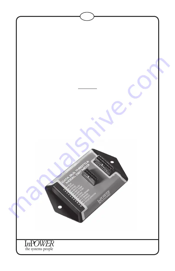
OWNERS MANUAL

InPower Model DBT-MD-01

Contents

1.  Introduction........................................ .................... 2

2.  Installation Procedures........................... ............... 3

     2.6  Harness Wire Table ........................................ 6

3.  Operation ............................................................... 7

4.  Mechanical Drawing .............................................. 9

5.  Status LED and Troubleshooting ........................... 10

     5.6  Troubleshooting Flowchart ............................. 11

6.  Contact Us ............................................................. 12

Electronic Throttle Module and Databus Decoder

for Ford 2016+ Vehicles

Содержание DBT-MD-01

Страница 1: ...4 2016 OWNERS MANUAL InPower Model DBT MD 01 Contents 1 Introduction 2 2 Installation Procedures 3 2 6 Harness Wire Table 6 3 Operation 7 4 Mechanical Drawing 9 5 Status LED and Troubleshooting 10 5 6 Troubleshooting Flowchart 11 6 Contact Us 12 Electronic Throttle Module and Databus Decoder for Ford 2016 Vehicles ...

Страница 2: ...ontinue to function so long as the unit has power and vehicle ignition is in the run position However the throttle functions will only operate if the Chassis Ready Conditions are satisfied LED diagnostic indicators are provided to aid in system troubleshooting These LEDs are located on the module opposite the connectors The DBT MD 01 kit includes two cables The first cable J1 Harness connects to t...

Страница 3: ...objects on the battery that can short the terminals together If battery acid gets in your eyes immediately seek first aid If acid gets on your skin immediately wash it off with soap and water 2 2 Getting Started IMPORTANTNOTE PleaseobtainthespecificSEICinstallationinstructions for your vehicle make and model from Ford Wire colors and locations may vary from model to model and even between differen...

Страница 4: ... function is not engaged the Databus Decoder signals will continue to operate If the Databus Decoder signals will not be used properly secure the Output wire group on the J1 harness A OBD II connector Locate the red connector on the J2 harness Route this portion of the cable to the OBD II Data Link Connector and plug it in The OBD II connector is usually located on the lower part of the dash on th...

Страница 5: ...rols and engine RPM All decoded signal output wires are located in the J1 harness in the bundle marked Outputs Each wire corresponds to a different signal and all wires give a 600mA current when connected Note The pink wire and the gray wire are unused in the standard model but may be given a custom signal at customer request Tape or otherwise properly secure any unused wires out Please see 2 6 on...

Страница 6: ...nction Signal Output Dark Green 1 Park Brake Set Ground Pink 9 Not used Positive Tan 10 Reverse Positive Violet 11 Engine Run Positive Dark blue 12 Park 750 Neutral Positive Gray 15 Not Used Ground J2 Harness Wire Color Pin Number Function Black 2 Ground out to Remote Orange 3 Input from 0 5V Remote Red 7 12V Power Input Violet 8 Not Used Gray 9 RPM Adjust Pink 10 Input from PWM Remote White 11 5V...

Страница 7: ...tivated by one of the Chassis Ready Conditions changing the engine will return to normal speed The throttle will flash the diagnostic LEDs to indicate the cause of the deactivation for ten seconds after Chassis Ready Conditions are restored Then it will reset and return the vehicle to high idle Modes of Operation Standby Mode Function Increase idle to minimum required to activate PTO Activation Ap...

Страница 8: ...ill flash until it receives a remote signal At that point the corresponding LED will turn solid and the other one will shut off 3 To adjust RPM with the potentiometer start at zero and then turn potentiometer up slowly until desired RPM is reached To adjust with PWM contact InPower for PWM specifications Minimum RPM Equal to Standby Mode RPM Maximum RPM Preset Adjustable Factory Default 1500 RPM M...

Страница 9: ...rsion Code A Date August 2016 Date Sept 14 2016 3 8 0 2 dia 4 4 2 6 J1 J2 0 4 0 8 www InPowerLLC com Made in the USA LOT 1234567890 36 20 20 to J1 to J2 MODULE CABLES All Dimensions in Inches Not to Scale Sensors Power PTO Inputs Outputs Diagnostic LEDs 4 Mechanical Drawing ...

Страница 10: ... substantially between different models and even different model years Please obtain and consult the SEIC information for your specific vehicle Documentation may be obtained from Ford s Truck Body Builder Advisory Service www fleet ford com truckbbas 5 3 A series of 11 LEDs on top of the module provide diagnostic information for troubleshooting purposes The LEDs are labeled and correspond to RPM m...

Страница 11: ...ore Chassis Condition LED flashing Park On Solid No Yes Bus On Solid RMT 0 5V Flash RMT PWM Flash RPM1 RPM2 STBY off All others On Solid Bus OFF RPM1 through RPM STBY Flashing Truck Not Supported Second device is connected to SEIC wirings and controllingRPM operation Operatingat Standby Speed waitingon remote input to control RPM Mode Selected Chassis Ready Condition Not Met Check flashinginterloc...

Страница 12: ...016 InPower LLC DBT MD 01 Owner s Manual 12 Document OM 194 Version Code A Date August 2016 Date Sept 14 2016 Contact Us InPower LLC 8311 Green Meadows Drive Lewis Center Ohio 43035 740 548 0965 www InPowerLLC com ...

Отзывы: