- 33 -
3 Wiring
3
Chapter 3 Wiring
CAUTION
DAnGER
●
Wiring must be performed by professional technicians.
● To avoid the electric shock, leave the servo drive for more than five minutes after powered
off, wait until the power indicator turns off completely, and check the voltage between P and
N by using a multimeter. Then, disassemble or assemble the drive.
●
Perform wiring after the servo drive and motor are installed properly. Failure to comply will
result in electric shock.
●
Do not damage the cables, lay them under large tension or pressure, or hang them. Failure
to comply may result in electric shock.
● Insulate the power terminal connectors to prevent electric shock.
● The specifications and installation method of external cables must comply with the
applicable local regulations.
●
The cables must be copper and the grounding cable must be the yellow-green one as
shown in Table 3-2.
●
The entire system must be grounded.
CAUTION
●
Carry out wiring correctly. Failure to comply will result in abnormal action of the servo motor
and personal injury.
● Do not mistake the terminal connection. Failure to comply may result in damage to the
terminals.
● Make sure to connect the electromagnetic contactor between the power supply and main
circuit of the drive (L1 and L2 for single-phase, and R, S and T for three-phase) to form
a structure that can cut off the power supply at the power supply side of servo drive. If
no electromagnetic contactor is connected, a fire may occur when a fault occurs and
continuous large current flows through the drive.
● Use the ALM (fault signal) to cut off the main circuit power supply. If the braking transistor
fails, the bleeder resistor may overheat, causing a fire.
● Before powering on, check the voltage specifications of the drive. NEVER connect the 380
V power supply to the 220 V drive. Failure to comply will damage the drive.
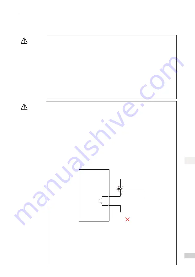
● Do not reverse the directions of the flywheel diode. Failure to comply will damage the drive
and affect signal output.
Servo Drive
External 5
−
24 V DC
DO1-
DO1+
6
7
Relay
External 0 V
Flywheel diode
polarity error
● Use a noise filter to reduce electromagnetic interference on electronic devices
around the drive.
● For the power supply and the main circuit connection, make sure that the main
circuit power supply is cut off and the servo ON state changes to the OFF state
after the alarm signal is detected.
●
Connect the U, V, W cables of the drive to the U, V, W terminals of the motor di-
rectly. Do not connect an electromagnetic contactor. Failure to comply may result
in abnormalities and faults.
Содержание SV820N Series
Страница 127: ...126 6 Trial Running 6 6 5 6 PLC Program 1 Add an FB file that edits the function block in the application...
Страница 128: ...127 6 Trial Running 6 2 The definition part of FB 3 Five function blocks in FB...
Страница 141: ...140 6 Trial Running 6 In section0 call the function block then the axis can be moved by the bus...
Страница 143: ...142 6 Trial Running 6 3 Open Visual studio and create a New Twincat3 Project...
Страница 146: ...145 6 Trial Running 6 Click OK Click OK...
Страница 147: ...146 6 Trial Running 6 Click Yes Click OK...
Страница 149: ...148 6 Trial Running 6 C The default RPDO list is as follows...
Страница 150: ...149 6 Trial Running 6...
Страница 152: ...151 6 Trial Running 6 7 Activate the configuration and switch over to the running mode Click...
Страница 157: ...156 6 Trial Running 6 Add a motion control library making it easy to call the control function block...
Страница 158: ...157 6 Trial Running 6 Create a new POU...
Страница 159: ...158 6 Trial Running 6 Create a new FB add MC_power MC_jog MC_home MC_absolute MC_reset to FB...
Страница 160: ...159 6 Trial Running 6 Call axis_motion in main Call the program in PLCTASK...
Страница 161: ...160 6 Trial Running 6 Compile the program if there is no fault configuration can be activated and then log in to the PLC...
Страница 181: ...Revision History Date Revised Version Revised Details May 2017 A00 First release...


