

1. Preface
Thank you for purchasing the AM600-RTU-ECT communication module developed and manufactured
independently by Inovance.
AM600-RTU-ECT is an EtherCAT bus slave expansion module used together with AM600 series medium-sized PLC
main modules. Each AM600-RTU-ECT module can connect up to 16 DI/DO modules, or 8 AI/AO modules.
Please read this guide carefully before using to ensure more safe usage. This guide describes the specifications,
characteristics and using methods of the AM600-RTU-ECT communication module for your reference. Please refer
to the AM600 Series PLC Hardware Manual (
"
Hardware Manual
"
) and the AM600 Series PLC Programming Manual to
understand the use of the user program development environment and design method of the user program of the
product. You can download the latest materials from
www.inovance.com
2. Safety Information and Precautions
Design Information and Precautions
Please read carefully this guide and any associated guides described in this guide before performing installation,
wiring, operation and inspection on this product. In addition, make sure to operate properly with adequate safety
assurance.
Safety information and precautions are identified into two grades: Warning and Caution.
WARNING
Indicates the improper operation which, if not avoided, may cause death or serious injury;
CAUTION
Indicates the improper operation which, if not avoided, may cause moderate or minor injury, as
well as equipment damage.
Design Information and Precautions
Please read carefully this guide and any associated guides described in this guide before performing installation,
wiring, operation and inspection on this product. In addition, make sure to operate properly with adequate safety
assurance.
Safety information and precautions are identified into two grades: Warning and Caution.
During control system design
WARNING
◆ The safety circuit must be designed to ensure that the control system can continue working safely when external power is off or
the PLC is faulty;
◆
In case of long-time over-current on the output circuit caused by a current exceeding the rated value or short-circuit of the load
equipment, the module may smoke or get on fire. Therefore, external safety devices should be used, such as fuses or breakers.
CAUTION
◆
An emergency stop circuit, a protection circuit, a forward/reverse operation interlocked circuit, and a upper position limit and
lower position limit interlocked circuit must be set in the external circuits of PLC to prevent damage to the machine.
◆ Please configure external protection circuit and safety mechanisms for output signals related to material accidents to ensure
that the equipment can work safely;
◆
Once PLC CPU detects abnormality in the system, all outputs may be closed; however, when a fault occurs in the controller
circuit, the output may not be under control. Therefore, it is necessary to design an appropriate external control circuit to
ensure normal operation of the equipment;
◆
If the PLC
'
s output units such as relays or transistors are damaged, the output may fail to switch between ON and OFF states
according to the commands;
◆
The PLC is designed to be used in indoor electrical environment (overvoltage category II). The power supply must have a
system-level lightning protection device, assuring that overvoltage due to lightning shock can
'
t be applied to the PLC
'
s power
supply input terminals, signal input terminals and output terminals and so forth, so as to avoid damage to the equipment.
1
During installation
WARNING
◆
The installation, wiring, maintenance and inspection of this product must be carried out by personnel who have received
necessary electrical training and experience.
◆ Disconnect all external power supplies of the system before module assembly/disassembly and wiring. Failure to do so may
result in electric shock, module fault or malfunction. Failure to do so may result in electric shock, module fault or malfunction.
◆
Do not use the PLC where there are dust, oil smoke, conductive dust, corrosive or combustible gases, or exposed to high
temperature, condensation, wind & rain, or subject to vibration and impact. Electric shock, fire and malfunction may also result
in damage or deterioration to the product.
◆
The PLC is an open-type device. To protect operators without adequate knowledge about electric devices from an electric
shock, the PLC must be mounted in a control cabinet with a door lock. The casing of the cabinet must meet IP20 or above safety
requirements. Only operators who have received related training about electric devices with adequate electric knowledge can
open the cabinet.
CAUTION
◆ While handling bolt holes and connecting wires, do not let cuttings and wire crumbs fall into the PLC through ventilation holes.
This may cause fire, faults and false trip;
◆ After a new PLC is installed, the ventilation surface of the PLC must not be covered. Otherwise, the ventilation efficiency will be
lowered, causing fire, faults and false trip;
◆ When modules are being mounted, the modules must be securely connected to their connectors and fixed on the hooks. If a
module is not mounted correctly, it may cause false trip, faults and the module to fall.
During wiring
WARNING
◆
The installation, wiring, maintenance and inspection of this product must be carried out by personnel who have received
necessary electrical training and experience.
◆ Disconnect all external power supplies of the system before wiring. Failure to comply may result in electric shock, module fault
or malfunction.
◆
The PLC can be powered on after installation and wiring. The terminal cover must be mounted before starting operations.
Failure to comply may result in electric shock.
◆
Perform good insulation on terminals so that insulation distance between cables will not reduce after cables are connected to
terminals. Failure to comply may result in electric shock or damage to the equipment.
CAUTION
◆ Prevent metal filings and wire ends from dropping into ventilation holes of the PLC at wiring. Failure to comply may result in
While handling bolt holes and connecting wires, do not let cuttings and wire crumbs fall into the PLC through ventilation holes.
This may cause fire, faults and false trip;
◆ The specifications and mounting method of external wiring must comply with the local power distribution regulations. Please
see the
"
Wiring
"
chapter in the user manual;
◆ To ensure safety of equipment and operator, use cables with sufficient diameter and connect the cables to ground reliably.
◆ Wire the module correctly after making clear of the connector type. If a cable is connected to a wrong terminal, it may cause
faults to the modules and external equipment;
◆ Tighten bolts on the terminal block in the specified torque range. If the terminal is not tight, short-circuit, fire or malfunction
may be caused. If the terminal is too tight, fall-off, short-circuit, fire or malfunction may be caused.
◆ If the connector is used to connect with external equipment, perform correct crimping or welding with the tool specified by
manufacturer. Poor connection may cause short circuit, fire or false trip;
◆
A label on the top of the module is to prevent foreign matters entering the module. Do not remove the label during wiring. Tear
down the label before starting the system to ensure ventilation;
◆
Do not bundle the control and communication cables together with the main circuit or power cables or put them close to each
other. The distance between them should be at least 100 mm. Otherwise, the noise may cause false trip;
◆
In application scenarios with serious interference, shielded cables should be used as the input or output cables of high-
frequency signals to ensure the resistance to interference;
During maintenance & inspection
WARNING
◆
The installation, wiring, maintenance and inspection of this product must be carried out by personnel who have received
necessary electrical training and experience.
◆
Touching terminals when the PLC is power-on may cause an electric shock or false trip;
◆
Disconnect all external power supplies of the system before cleaning the module or re-tightening screws on the terminal block
or screws of the connector. Failure to comply may result in electric shock.
◆
All external power supplies must be disconnected from the system before modules can be disassembled or communication
cables can be connected or disconnected. Failure to comply may result in electric shock or malfunction.
CAUTION
◆ Get acquainted with the guide and ensure safety before online modification, forcible output, and RUN/STOP operation.
◆
Disconnect the power supply before installing/removing the extension card.
At disposal
CAUTION
◆
Treat the product as ordinary industrial waste.
◆
The retirement of batteries should comply with the local regulations.
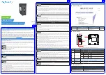
3. Product Information
■
Model and Nameplate
1SPEVDU*OGPSNBUJPO
". *OPWBODFNFEJVNTJ[FE
1-$BVUPNBUJPONPUJPO
4FSJFT
TFSJFTDPOUSPMMFS
3FNPUF$PNNVOJDBUJPO1SPUPDPM
&$5
/BNFQMBUF
.PEVMF5ZQF
".356&$5
3FNPUFJOUFSGBDFNPEVMF
&UIFS$"5
&UIFS$"5
.0%&- ".356&$5
108&3*/165
7%$
065165 /0/&
7&3 YYYYY
:&
:&
Figure 1
Description of model and nameplate
Model
Classification
Description
Applicable to
AM600-RTU-ECT
EtherCAT communication module
CANopen protocol communication
interface module
AM600
■
External Interface
EtherCAT
OU
T
IN
SF
BF
POWER
RUN
24V
5V
GND
GND
ECT
4JHOBMJOEJDBUPST
&UIFS$"5DPNNVOJDBUJPOJOUFSGBDF
-PDBMFYUFOTJPO
CBDLFOEJOUFSGBDF
7JOUFSOBM
QPXFSJOQVUUFSNJOBM
Figure 2
Diagram of EtherCAT communication module interface
No.
Interface Name
Function
1
IN
EtherCAT input interface
OUT
EtherCAT output interface used to connect a back-end EtherCAT slave
2
Signal indicators
POWER
Power indicator
Green ON when power supply is switched on.
RUN
Indicator
Green ON when the module is in normal operation
SF
Expansion bus
error indicator
Red
ON when error occurs on the expansion bus
BF
Communication
error indicator
Red
ON when communication error occurs
3
Local expansion
module back-end
interface
Connect back-end module, not supporting hot plugging
4
Internal 24 V power
input terminal
Connect to power modules
■
General Specifications
Item
Specifications
Power supply specifications
24 VDC (20.4 VDC to 28.8 VDC) (–15% to +20%)
Communication protocol
EtherCAT industrial real-time bus protocol
Maximum communication speed
Ethernet 100 Mbps
2
3
19010639
A01
User Guide
AM600-RTU-ECT
EtherCAT Communication Module


