background image


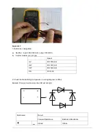
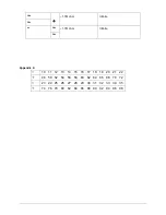
~1.7M ohm 

Infinite   


~1.7M ohm 

Infinite   


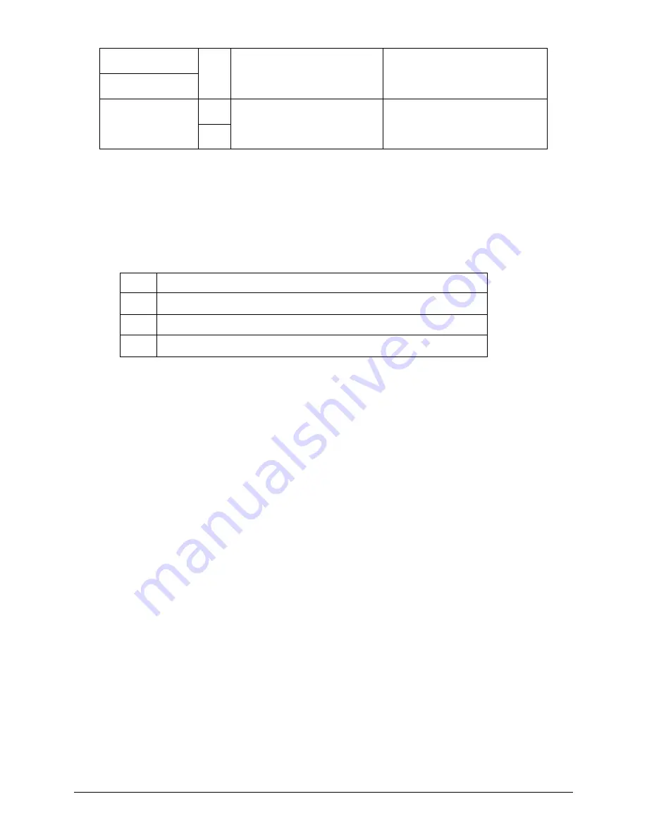
Appendix 4: 


10  11  12  13  14  15  16  17  18  19  20  21  22 


48  50  52  54  56  58  60  62  64  66  68  70  72  


23  24  25  26  27  28  29  30  31  32  33  34  35 


74  76  78  80  82  84  86  88  90  92  94  96  98 


Содержание VOM20H2RE102

Страница 1: ...SERVICE MANUAL DC INVERTER MULTI TYPE VOM20H2RE102 VOM30H2RE103 VOM42H2RE104 DC MULTI OUTDOOR UNITS 1 ...

Страница 2: ...information of Outdoor Units 2 2 Features 3 3 Dimensions 4 4 Wiring Diagram 5 5 Refrigeration Cycle Diagram 7 6 Indoor units combination 9 7 Installation Details 10 8 Electronic control function 20 9 Troubleshooting 24 1 ...

Страница 3: ...tion of Outdoor Units Model name Dimension mm in Compressor VOM20H2RE102 845x320x700 33 3x12 6x27 6 DA130S1C 20FZ VOM30H2RE103 845x320x700 33 3x12 6x27 6 DA150S1C 20FZ VOM42H2RE104 990x345x965 39x13 6x38 TNB306FPGMC L 2 ...

Страница 4: ...ting operation mode except defrosting operation It protects the valves and prevents water from dripping Outdoor unit Power relay control Hydrophilic aluminum fin Anti rust cabinet Valve protection cover 4 way valve control Low noise air flow system Discharge pipe temperature protection Compressor crankcase heater 3 ...

Страница 5: ...3 Dimensions Model Dimension mm in W D H W1 A B VOM20H2RE102 845 33 3 320 12 6 700 27 6 908 35 7 560 22 335 13 2 VOM30H2RE103 VOM42H2RE104 990 39 345 13 6 965 38 1075 42 3 624 24 6 366 14 4 4 ...

Страница 6: ...4 Wiring Diagram 4 1 VOM20H2RE102 4 2 VOM30H2RE103 5 ...

Страница 7: ...4 3 VOM42H2RE104 6 ...

Страница 8: ...ILIARY B LIQUID VALVE B GAS VALVE B Accumulator T2B A Evaporator temp sensor outlet T2B B 5 2 Refrigeration circuit drawing of inverter tri zone LIQUID VALVE A GAS VALVE A HEAT EXCHANGE EVAPORATOR HEAT EXCHANGE CONDENSER Compressor 4 WAY VALVE COOLING HEATING T2 Evaporator temp sensor middle T1 Room temp sensor T3 Condenser temp sensor T5 Discharge temp sensor T4 Ambient temp sensor INDOOR OUTDOOR...

Страница 9: ...dle T1 Room temp sensor T3 Condenser temp sensor T5 Discharge temp sensor T4 Ambient temp sensor INDOOR OUTDOOR EXV A CAPILIARY A CHECK VALVE CAPILIARY TUBE EXV B CAPILIARY B LIQUID VALVE B GAS VALVE B EXV C CAPILIARY C LIQUID VALVE C GAS VALVE C EXV D CAPILIARY D LIQUID VALVE D GAS VALVE D Accumulator High pressure switch Low pressure switch T2B A Evaporator temp sensor outlet T2B B T2B C T2B D 8...

Страница 10: ...be Floor Ceiling or Duct unit There should be only one Floor Ceiling or Duct unit 12 18 TRI 1x2 9 9 9 12 9 18 12 12 12 18 TRI 1x3 9 9 9 9 9 12 9 9 18 9 12 12 6 3Indoor unit combination for VOM42H2RE104 Comb Suggested C bi ti Limit QUA 1x1 9 None 12 18 QUA 1x2 9 9 9 12 9 18 12 12 12 18 18 18 QUA 1x3 9 9 9 9 9 12 9 9 18 9 12 12 9 12 18 9 18 18 12 12 12 12 12 18 12 18 18 QUA 1x 4 9 9 9 9 9 9 9 12 9 9...

Страница 11: ...ft 60 200ft Max length for one IU m 20 65 6ft 25 82ft 30 98ft Max height difference between IU and OU m OU higher than IU 10 33ft 10 33ft 10 33ft OU lower than IU 15 49 2ft 15 49 2ft 15 49 2ft Max height difference between IUs m 10 33ft 10 33ft 10 33ft Additional refrigerant charge 1 drive 2 1 drive 3 1 drive 4 Chargeless pipe length m 15 49 2ft 22 5 73 8ft 30 98 4ft Additional refrigerant charge ...

Страница 12: ...ock capillary tubing Water may lead to corrosion of parts in the refrigerant system Therefore the indoor units and the pipes between indoor and outdoor units must be leak tested and evacuated to remove gas and moisture from the system Gas leak check Soap water method Apply soap water or a liquid neutral detergent on the indoor unit connections or outdoor unit connections by a soft brush to check f...

Страница 13: ... stop the operation of the vacuum pump Confirm that the gauge needle does not move approximately 5 minutes after turning off the vacuum pump 7 Turn the flare nut of the 3 way valves about 45 counterclockwise for 6 or 7seconds after the gas coming out then tighten the flare nut again Make sure the pressure display in the pressure indicator is a little higher than the atmosphere pressure Then remove...

Страница 14: ...o the open position Be sure to use a hexagonal wrench to operate the valve stems 7 Mount the valve stems nuts and the service port cap Be sure to use a torque wrench to tighten the service port cap to a torque 18N m Be sure to check the gas leakage 3 Adding the refrigerant if the pipe length 5m Procedure 1 Connect the charge hose to the charging cylinder open the 2 way valve and the 3 way valve Co...

Страница 15: ...f the air conditioner before disconnecting the hose 7 Mount the valve stem caps and the service port Use torque wrench to tighten the service port cap to a torque of 18N m Be sure to check for gas leakage 7 5 Adding the refrigerant after running the system for many years Procedure 1 Connect the charge hose to the 3 way service port open the 2 way valve and the 3 way valve Connect the charge hose t...

Страница 16: ...service port Use torque wrench to tighten the service port cap to a torque of 18N m Be sure to check for gas leakage 7 6 Re installation while the indoor unit need to be repaired 1 Collecting the refrigerant into the outdoor unit Procedure 1 Confirm that both the 2 way and 3 way valves are set to the opened position Remove the valve stem caps and confirm that the valve stems are in the opened posi...

Страница 17: ... port cap to a torque of 1 8 kgf m Be sure to check for gas leakage 2 Air purging by the refrigerant Procedure 1 Confirm that both the 2 way and 3 way valves are set to the closed position 2 Connect the charge set and a charging cylinder to the service port of the 3 way valve Leave the valve on the charging cylinder closed 3 Air purging Open the valves on the charging cylinder and the charge set P...

Страница 18: ...perate the valve stems 7 Mount the valve stems nuts and the service port cap Be sure to use a torque wrench to tighten the service port cap to a torque 18N m Be sure to check the gas leakage 7 7 Re installation while the outdoor unit need to be repaired 1 Evacuation for the whole system Procedure 1 Confirm that both the 2 way and 3 way valves are set to the opened position 2 Connect the vacuum pum...

Страница 19: ...needle does not move approximately 5 minutes after turning off the vacuum pump 5 Disconnect the charge hose from the vacuum pump 18 ...

Страница 20: ... side on the charge set and charge the system with liquid refrigerant If the system cannot be charge with the specified amount of refrigerant or can be charged with a little at a time approximately 150g each time operating the air conditioner in the cooling cycle however one time is not sufficient wait approximately 1 minute and then repeat the procedure 5 When the electronic scale displays the pr...

Страница 21: ...nit point check function There is a check switch in outdoor PCB Push the switch SW1 to check the states of unit when the unit is running The digital display tube will display the follow procedure when push SW1 each time Display Remark 1 Indoor unit capacity demand code 2 Outdoor unit running mode code Off 0 Cooling 1 Heating 2 3 Amendatory capacity demand code 4 Outdoor unit fan motor state Off 0 ...

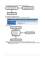
Страница 22: ... data 23 B indoor unit room temp T1B Actual data 24 B indoor unit evaporator temp T2B Actual data 25 C indoor unit room temp T1C Actual data 26 C indoor unit evaporator temp T2C Actual data 27 D indoor unit room temp T1D Actual data 28 D indoor unit evaporator temp T2D Actual data 29 Check point over 8 5 Protection 8 5 1 Three minutes delay at restart for compressor 8 5 2 Temperature protection of...

Страница 23: ...eat_F4 via capacity demand HEAT_F11 IHEATLMT7 HEAT_F10 IHEATLMT6 HEAT_F9 IHEATLMT5 HEAT_F8 IHEATLMT4 HEAT_F7 IHEATLMT3 HEAT_F6 IHEATLMT2 HEAT_F5 IHEATLMT1 If the current frequency is lower than HEAT_F4 the frequency will not be limited After 10s of the compressor start if the current IHEAT the AC will display the failure for 30 seconds and stop The AC will restart 3 minutes later 8 5 5 Indoor outd...

Страница 24: ... mode A weak current flow through the coil of compressor from the wiring terminal of compressor then the compressor is heated without operation Preheating release condition If T4 5 or the compressor starts running preheating function will stop 8 5 10 Compressor crankcase heater When T4 3 and the compressor is not running the crankcase heater will be active When T4 5 or the compressor starts up the...

Страница 25: ...er than 15 C optional function P4 Inverter compressor drive protection P7 P5 Mode conflict For VCM1013H21 VCM1320H21 Operation Timer De frost Alarm Failure X X X Open or short circuit of T1 temperature sensor X X X Open or short circuit of T2 temperature sensor X X X Indoor outdoor units communication error X X X Full water malfunction X X Indoor EEPROM malfunction X X IPM module protection X X Op...

Страница 26: ...il outlet temp sensor or connector of sensor is defective E2 No B Indoor unit coil outlet temp sensor or connector of sensor is defective E3 No C Indoor unit coil outlet temp sensor or connector of sensor is defective E6 No D Indoor unit coil outlet temp sensor or connector of sensor is defective E4 Open or short circuit of outdoor temperature sensor T4 E5 E6 E5 Voltage protection P1 P0 E7 Communi...

Страница 27: ...ly Otherwise check whether the EEPROM chip plugged in PCB well Yes No Yes Insert the EEPROM well Replace the indoor PCB Shut off the power supply and turn it on 1 minute later Is it still displaying the error code EEPROM a read only memory whose contents can be erased and reprogrammed using a pulsed voltage EERROM chip may be solid for some models ...

Страница 28: ... by remote controller Is all indoor unit display Turn off the all indoor units Is IPM power LED lamp On Refer PIC 3 Yes Is PFC power LED lamp off Refer PIC 3 Yes A Is all the wiring between terminal and Indoor PCB connect ok No Yes A No Reconnect the wiring Is indoor units number correct Check on the outdoor check point 18 2 for dual zone 3 for tri zone 4 for qua zone Refer PIC 5 Is Main board lam...

Страница 29: ...and unit standby PIC 5 check point bottom press 18 times for check how many indoor units are connected Pic 1 Measure the voltage of L2 to S Vs is it moving alternately between positive value and negative value PIC 3 IPM For dual tri qua zone PFC qua zone only ...

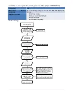
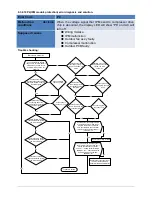
Страница 30: ...ying the error code Shut off the power supply rotate the fan by hand Does it rotate properly The unit operates normally Replace indoor fan motor Check the wires of fan motor Are all the connections good No Yes No Correct the connections No Yes Replace indoor main PCB Is it still displaying the error code Yes Yes Check the voltage between port 1 and 6 of fan motor connector is it 310V No DC motor v...

Страница 31: ...ate the cross fan by hand Does it rotate properly The unit operates normally Disassembly the connection between fan and motor check if the bearing is normal Replace the bearing Check the wires of fan motor Are all the connections good No Yes No No Replace indoor fan motor Yes Correct the connections No No Yes Yes Check the resistance value of indoor fan motor is it normal Replace indoor PCB Yes ...

Страница 32: ...e sensor Check the resistance value of the sensor via Appendix 1 Is it normal No 9 3 1 7 Full water malfunction For cassette ceiling Floor A5 duct If the water level switch is inserted well No Insert the water level switch well If the water level switch is broken Yes Replace the water level switch If the water pump is normal No Replace the water pump Yes No Yes Check PCB board or replace the indoo...

Страница 33: ... solution Error Code E0 Malfunction decision conditions PCB main chip does not receive feedback from EEPROM chip Supposed causes Installation mistake PCB faulty Trouble shooting If the EEPROM chip is welded on PCB replace the PCB directly Otherwise check whether the EEPROM chip plugged in PCB well Yes No Yes Insert the EEPROM well Replace the outdoor main board Outdoor EEPROM malfunction 9 3 2 2E4...

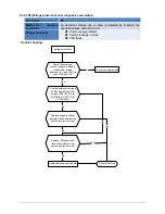
Страница 34: ...hooting Voltage protection Check the voltage of outdoor unit power supply whether the voltage between L L1 and N L2 is about 220 240VAC Check the power supply Check whether the voltage of IPM board P and N is normal DC277 356V for 18 27KBtu h DC277 410V for 36KBtu h Replace bridge rectifiers and then check whether the system can run normally Replace IPM board and then check whether the system can ...

Страница 35: ...oting Communication malfunction between IPM board and outdoor main board Is there at least one LED in the IPM board light Check the signal wire between the IPM module and the main board is it connected good Reconnect and retry Is error still display Replace IPM board and then check whether the system can run normally Replace the electric control box No No No No Yes Trouble is solved No Yes Replace...

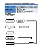
Страница 36: ...System block Outdoor PCB faulty Trouble shooting Temperature protection of compressor top Whether compressor operates Whether refrigerant circulation volume is normal Whether abnormality is the same after gas charging Yes No No Reconnect and retest No Check refrigerant system such as clogging of capillary etc No Whether the connection is good Replace the outdoor main PCB Yes Replace the protector ...

Страница 37: ...g Temperature protection of compressor discharge Check whether the compressor discharge temp is more than 115 C Check whether the wiring connection is right between compressor discharge temp sensor and PCB according to wiring diagrams Method Check whether the resistance of compressor discharge temp sensor is right refer to the Appendix 2 No Yes Yes Trouble is solved No Judge The discharge temp sen...

Страница 38: ...socket check whether the system can run normally Yes No Connect it well Replace outdoor main board No Replace high pressure protector Yes Judge 2 Whether the high pressure protector is broken Check whether the refrigerant system is ok Judge 3 Check whether the outdoor ambient temperature is higher than 43 No Stop the unit Yes Judge 4 Check whether the outdoor unit is bad ventilation No Make the ou...

Страница 39: ...ressure protector Yes Judge 2 Whether the low pressure protector is broken Check whether the refrigerant system is ok Judge 3 Check whether the outdoor ambient temperature is too low No Stop the unit Yes Method Connect the pressure gauge to the gauge joint of the system check whether the pressure is lower than 0 14MPa No Leak hunting Charge nitrogen or refrigerant to the system if the leakage is s...

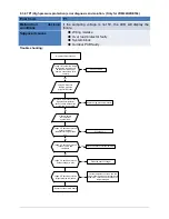
Страница 40: ...s 14 5A For 36K it is 20A Yes Replace the electric control box Check whether the refrigerant system is ok Judge 2 Check whether the outdoor ambient temperature is higher than 50 No Stop the unit Yes Judge 3 Check whether the outdoor unit is bad ventilation No Make the outdoor unit ventilate well Yes Judge 5 The refrigerant pipe is blocked No Let the refrigerant out then use the high pressure nitro...

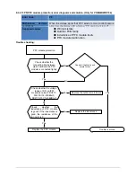
Страница 41: ...ule is connected tightly Yes Connect it tightly check ok or not No No No Connect it well check ok or not Check whether the connecting line of the compressor is connected correctly or tightly Replace the IPM module check whether the system can work normally No No Replace the main board check whether the system can work normally No Replace the compressor check whether the system can work normally Ye...

Страница 42: ...ture is more than 65 C Yes Judge 1 Check whether the outdoor ambient temperature is higher than 50 No Judge 3 The refrigerant pipe is blocked Let the refrigerant out then use the high pressure nitrogen or refrigerant to blow pipe vacuumize and charge the refrigerant again Yes Judge 2 Check whether the heat exchanger is dirty No Clean the heat exchanger Yes Replace outdoor main board Yes Check whet...

Страница 43: ... module malfunction Trouble shooting PFC module protection Check whether the connecting line between main board and the PFC module is connected tightly Yes Check whether the voltage range of P N on IPM module is normal DC277 356V for 18 27KBtu h DC277 410V for 36KBtu h No Check whether the inductance of PFC module is good If the inductance is good the resistance of the two ports is 0 Yes Replace t...

Страница 44: ... 0 40060 3 41 5878 37 5 87359 77 1 29078 117 0 38991 2 39 8239 38 5 62961 78 1 25423 118 0 37956 1 37 1988 39 5 39689 79 1 21330 119 0 36954 0 35 2024 40 5 17519 80 1 17393 120 0 35982 1 33 3269 41 4 96392 81 1 13604 121 0 35042 2 31 5635 42 4 76253 82 1 09958 122 0 3413 3 29 9058 43 4 57050 83 1 06448 123 0 33246 4 28 3459 44 4 38736 84 1 03069 124 0 32390 5 26 8778 45 4 21263 85 0 99815 125 0 31...

Страница 45: ... 8 084 115 2 422 4 222 8 36 34 32 76 7 82 116 2 357 3 211 4 37 32 94 77 7 566 117 2 294 2 200 7 38 31 62 78 7 321 118 2 233 1 190 5 39 30 36 79 7 086 119 2 174 0 180 9 40 29 15 80 6 859 120 2 117 1 171 9 41 28 81 6 641 121 2 061 2 163 3 42 26 9 82 6 43 122 2 007 3 155 2 43 25 86 83 6 228 123 1 955 4 147 6 44 24 85 84 6 033 124 1 905 5 140 4 45 23 89 85 5 844 125 1 856 6 133 5 46 22 89 86 5 663 126...

Страница 46: ...Inverter module U V W 3ph Result U V 60 150V AC U W 60 150V AC V W 60 150V AC P N DC 310V 2 Check the Diode Bridge component In wiring diagram rectifier Remark If this part is abnormal the LED will not light Multi meter Result Forward Resistance Backward Resistance _ Infinite Infinite ...

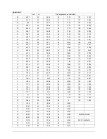
Страница 47: ...1 7M ohm Infinite 1 7M ohm Infinite Appendix 4 10 11 12 13 14 15 16 17 18 19 20 21 22 48 50 52 54 56 58 60 62 64 66 68 70 72 23 24 25 26 27 28 29 30 31 32 33 34 35 74 76 78 80 82 84 86 88 90 92 94 96 98 ...

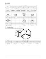
Страница 48: ...G20B RPG28H Model 9k 9A 12k 9A 18k 9A Indoor fan motor RPG20B RPG20B RPG28H Model 12k A5 18k A5 Indoor fan motor YSK27 4G YSK68 4B Model 12k Cassette 18k Cassette Indoor fan motor YDK45 6B YDK45 6B Model 12k Ceiling Floor 18k Ceiling Floor Indoor fan motor YSK25 6L YSK25 6L 1 Compressor checking Measure the resistance value of each winding by using the tester Position Resistance Value DA130S1C 20F...

Страница 49: ... 24 5Ω 8 20 317Ω 8 20 145Ω 8 20 345Ω 8 20 627Ω 8 20 88 5Ω 8 20 Red Yellow 76Ω 8 20 19Ω 8 20 252Ω 8 20 88Ω 8 20 150Ω 8 20 374 3Ω 8 20 138Ω 8 20 Yellow Blue 76Ω 8 20 19Ω 8 20 252Ω 8 20 88Ω 8 20 150Ω 8 20 374 3Ω 8 20 138Ω 8 20 Measure the resistance value of each winding by using the tester Position Resistance Value RPG20B RPG28H Black Red 381Ω 8 20 183 6Ω 8 20 White Black 267Ω 8 20 206Ω 8 20 ...

Отзывы: